1
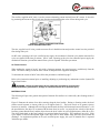
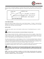
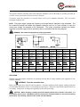
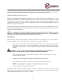
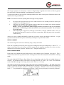
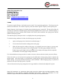
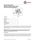
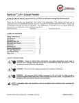
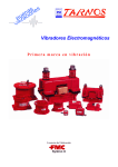
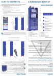
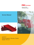
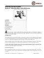
SERVICE INSTRUCTIONS
Syntron® Vibrating Base Units EB Series
CONTENTS
Introduction…………………………………………………
Material Flow……………………………………………….
Long-Term Storage….………………………………………
Installation……….………………………………………….
Operation……………………………………………………
Maintenance…………………………………………………
Troubleshooting Guide………..…………………………….
Air Gap Adjustments..………………………………………
Feeder Current……………………………………………….
Parts Feeder Stroke…………………………………………..
Tuning………………………………………………………..
PAGE
1
2
3
3
4
5
6
6
7
7
8
Safety Instruction: Product Safety Labels must remain highly visible on the equipment. Establish a
regular schedule to check visibility. Should safety labels require replacement, contact Homer City Automation for
an additional supply free of charge.
INTRODUCTION
The Syntron® EB Series Parts Feeder assembly is a dynamically balanced, two-mass vibrating system consisting
of a bowl and bowl mounting cross-arm coupled to an electromagnetic drive by means of leaf springs. The base
of the unit is isolated from the supporting structure by rubber isolator springs (mounting feet).
The drive assembly consists of a core and an armature. The core is connected directly to the base. The armature
assembly is located opposite the core assembly and is connected directly to the bowl mounting cross-arm.
A system of leaf springs is connected at the top to the cross-arm and at the bottom to the base. The bowl, crossarm and armature assembly is joined to the base only by the leaf spring assemblies. Figure 1 illustrates the basic
construction of the Model EB Parts Feeder assembly.
AC versus RC operation
Power is supplied to the feeder coils of an EB series vibrating base unit through a separate control. This control,
in its simplest form, consists of fuses, control rheostat, switchgear and either a rectifier (on RC units) or a triac (on
AC units).
©2010 Homer City Automation, Inc. All rights reserved.
SM0690 082010
The rectifier, supplied on RC units, is used to convert alternating current into half-wave DC current. It does this
by permitting the current to flow in only one direction and controlling the value of flow during each cycle.
FIGURE 1 – BASIC CONSTRUCTION OF EB
PARTS FEEDER DRIVE UNIT
The triac, supplied on AC units, permits current to flow in both directions and provides control over the period of
flow during each cycle.
On RC units, operating at 60-cycle rectified power supply, the mechanical vibration cycle and the material flow
cycle are repeated 3600 times per minute. On AC units, operating at 60-cycle triac controlled power supply, the
mechanical vibration cycle and the material flow cycle are repeated 7200 times per minute.
AC Feeder Current
When reading the current of an AC unit with a clamp-on ammeter, the actual current is read directly from the
meter. The meter reading reveals the same current as stamped on the equipment nameplate.
To determine the current of an RC unit, follow the procedure as outlined on page 7.
Refer to this instruction manual prior to installing, adjusting or performing any maintenance on the Syntron EB
Series Parts Feeders.
WARNING: Failure to follow these Service Instruction procedures could result in
unsatisfactory performance, damage or shortened service life or personal injury.
MATERIAL FLOW
The following will provide a general description of material flow and how it is achieved by the vibrating stroke of
the bowl.
Figure 2 illustrates the action of an object moving along the bowl surface. During a vibrating stroke, the bowl
surface travels between its lowest point (A) to its highest limit (C). The bowl travels at its greatest velocity
between (A) and (B). Although still traveling up and forward, the bowl will decelerate between (B) and (C). On
the upward stroke, the object is in contact with the bowl from (A) to (B). At point (B), the velocity of the object
becomes greater than the bowl, and the object leaves the bowl surface on a free-flight trajectory from (B) to (D).
The object lands back on the bowl surface at a position further forward (D). This completes one cycle. Each
cycle imparts a forward and upward flight of the object and it lands further along the bowl track toward the
discharge. On equipment operation at 60-cycle rectified power supply, this cycle of material flow is repeated
3600 times per minute.
2
The rate of feed is controlled by adjusting or varying the stroke of the bowl. The number of strokes will remain
constant to the power supply, but the stroke length can be varied by the control knob to increase or decrease feed
rate.
FIGURE 2 – MATERIAL FLOW ON BOWL SURFACE
LONG-TERM STORAGE
Inspect parts feeder for damage which may have occurred during shipment. If damage is found, notify the
shipping carrier and Homer City Automation promptly. Store the unit in a clean, dry storage area. Do not drop
the parts feeder, as the impact could cause damage.
INSTALLATION
The feeder and controller, when received, should be carefully uncrated. All packing bands, paper, etc., must be
removed.
CAUTION: Homer City Automation recommends lifting the unit by the base.
When selecting a location for the feeder, consideration must be given to the area of support. Larger units can
weigh over 600 lbs. (272 kg), and a support must be selected that will safely carry the full weight of the unit under
loaded operating conditions. The operating frequency of the unit versus the natural frequency of the support
structure is most important, and the following points must be carefully observed:
The support structure must have a natural frequency of at least 1-1/2 times the operating frequency of the bowl
feeder. Any supporting structure having a natural frequency close to the operating frequency of the bowl feeder is
evidenced by excessive dynamic deflections at the points of support and can result in poor performance of the
bowl feeder. These conditions can be corrected by stiffening the supports with bracing, etc.
It is important to bolt the Syntron EB Parts Feeder in its operating location with the foot locators to prevent
misalignment of discharge location. Refer to Table I for dimensions for mounting the isolator base.
WARNING: Do not operate the unit without first installing the rubber isolators with locators on the
base. The feeder unit must never come in contact with any rigid object or adjacent surface that could
hamper the vibrating action of the feeder. Any connections between the bowl and adjacent object must
be flexible.
NOTE: Never make any alterations or additions to the Parts Feeder Assembly without first contacting
the Homer City Automation. Homer City Automation will not assume responsibility for unauthorized
alterations or additions to bowl or drive assemblies.
3
The separate controller assembly (when used) should be installed as close to the feeder as possible, preferably on
a wall in a clean, dry location, free from excessive vibration.
If possible, install the controller at a location where it will receive adequate ventilation. This will ensure
prolonged component life.
NOTE: The power supply voltage and frequency must equal what is stamped on the nameplate. The
line conductor between the feeder and separate controller must be of a size sufficient to carry the
current and voltage as stamped on the nameplate. The wiring connections between the feeder,
controller and power supply must be securely made in accordance with the wiring diagram.
WARNING: Be certain the equipment is properly grounded!
A
B
C
D
E**
F
G
EB-05
4-1/2”
(114 mm)
5-1/2”
(140 mm)
6-7/8”
(174 mm)
1/16”
(1 mm)
4-3/4”
5-1/32”
(121 mm)
(128 mm)
--9/32”Φ
(7 mm)
EB-09
7-3/4” Sq.
(197 mm)
9-1/4” Sq.
(235 mm)
10-3/4”
(273 mm)
1/8”
(3 mm)
8-3/4”
9-1/4”
(222 mm)
(235 mm)
2-1/4”
(57 mm)
11/32”Φ
(9 mm)
EB-11
9-1/2” Sq.
(241 mm)
11” Sq.
(279 mm)
12-1/2”
(318 mm)
1/8”
(3 mm)
8-3/4”
9-1/4”
(222 mm)
(235 mm)
2-1/4”
(57 mm)
11/32”Φ
(9 mm)
EB-14
12-1/2” Sq.
(317 mm)
14” Sq.
(356 mm)
15-1/2”
(394 mm)
1/8”
(3 mm)
8-3/4”
9-1/4”
(222 mm)
(235 mm)
2-1/4”
(57 mm)
11/32”Φ
(9 mm)
EB-17
15-1/2” Sq.
(394 mm)
17” Sq.
(432 mm)
18-1/2”
(470 mm)
1/8”
(3 mm)
8-3/4”
9-1/4”
(222 mm)
(235 mm)
2-1/4”
(57 mm)
11/32”Φ
(9 mm)
EB-18
16” Sq.
(406 mm)
18-1/2” Sq.
(470 mm)
20-1/4”
(514 mm)
1/8“
(3 mm)
12-1/2”
13”
(317 mm)
(330 mm)
3-1/2”
(89 mm)
11/32”Φ
(9 mm)
EB-22
19-1/2” Sq.
(495 mm)
22” Sq.
(559 mm)
23-3/4”
(603 mm)
1/8”
(3 mm)
12-1/2”
13”
(317 mm)
(330 mm)
3-1/2”
(89 mm)
11/32”Φ
(9 mm)
EB-27
24-1/2” Sq.
(622 mm)
27” Sq.
(686 mm)
28-3/4”
(730 mm)
1/8”
(3 mm)
12-1/2”
13”
(317 mm)
(330 mm)
3-1/2”
(89 mm)
11/32”Φ
(9 mm)
EB-32
29-1/2” Sq.
(749 mm)
----1/8”
(3 mm)
12-3/8”
13”
(315 mm)
(330 mm)
3-1/2”
(89 mm)
11/32”Φ
(9 mm)
TABLE I – OUTLINE DIMENSIONS OF EB PARTS FEEDER DRIVE UNIT
OPERATION
With the equipment properly installed in its operating location and all wiring completed, the equipment is now
ready for operation.
WARNING: Close the controller door.
Before energizing the unit, check all bolts for tightness. Check the method of feeder support, making certain that
it is substantial and that the feeder is not touching any rigid objects. Rotate the control knob counterclockwise to
zero setting. Energize the switchgear and gradually increase the knob setting.
CAUTION: When operating normally, the feeder should perform with a smooth, even stroke. If a
loud striking noise occurs, immediately turn the control knob counterclockwise to zero and the striking
should stop. If the striking continues, turn off the unit immediately!!
4
Striking is the result of the armature and core making contact. Continued striking can result in serious damage to
the unit. Refer to the Air Gap section on page 6 for the procedure to correct a striking condition.
Load the bowl with the parts to be conveyed.
Homer City Automation recommends the quantity of parts loaded in the bowl be determined so as not to
interfere with the feed rate or orientation features of the bowl. Usually one layer of parts is satisfactory. Adjust
the control knob to the desired output. Clockwise rotation will increase feed rate, while counterclockwise rotation
will decrease the feed rate. The parts will flow along the bowl track in a smooth and controlled rate of feed
toward the discharge end of the bowl.
Many units incorporate bowls designed with special clips, rejectors, wipers, air jets, track modifications, etc., for
positioning and orienting parts for a specific application. These devices, placed along the track and bowl wall, are
installed to exacting measurements.
NOTE: Any damage or mechanical change to these features may stop the flow of parts or alter their
orientation. Instructions for these special features are not included in this manual. These applications
are described in special instructions furnished with the particular unit.
MAINTENANCE
Syntron EB Parts Feeders require minimum preventive maintenance when installed properly and under normal
operating conditions. However, the following points should be given careful consideration:
1.
Some materials tend to adhere and build up on the bowl surfaces. This is especially true of materials
containing a greasy covering or any pulverized substance. Material build-up on the bowl should be
removed as a daily practice. Look for material build-up particularly around and under hopper
openings.
WARNING: A clean, dry compressed air supply is recommended for general cleaning of
these units. The use of water may result in shorting of electrical components.
Diluted household ammonia or most common detergents are effective cleaning agents. Do not use
cleaners containing chloride.
2.
All details of the feeder magnet and controller should be kept reasonably clean.
3.
Never oil the spring assemblies. This destroys the clamping effect of the spring pads.
NOTE: If spring stacks are repainted, do not paint between the springs.
4.
The controller door should always be kept closed.
Units designed with air-operated orientation features will require a regulated dry air supply. This supply system
should consist of an air filter, regulator, and flexible air line. Unless otherwise specified, the air pressure supply
at the manifold should always be set at 50 p.s.i. (.34 Mpa.).
5
TROUBLESHOOTING
MALFUNCTION
Feeder operating below capacity
(too slow)
PROBABLE CAUSE
Low voltage
CORRECTIVE ACTION
Check power supply
Feeder in contact with rigid object
Remove restriction
Loose bowl
Tighten bowl attachments
Broken or dirty leaf springs
Clean or replace*
Spring bolts improperly torqued
See separate instructions for proper
torque
Bowl or
broken
cross-arm
cracked
or
Unit improperly tuned
Feeder operating below capacity
(amplitude correct, but feed rate
low)
Feeder hums – will not vibrate
Feeder fails
response)
to
operate
Refer to tuning instructions in this
manual
A single layer of parts should be
sufficient
Bowl overloaded
Bowl worn out
Repair or replace* as required
Improper air pressure at manifold (if
supplied)
Unless
otherwise
noted,
air
pressure at manifold should be 50
p.s.i.
Special orientation features
supplied) improperly adjusted
Adjust as required
Defective SCR or rectifier
(no
Repair or replace* as required
(if
Coil failure
See controller
testing
*Replace
Blown fuse
*Replace
Faulty switchgear
*Replace or repair
instructions
for
Short in electrical wiring
Repair
*Replace only with parts supplied, or recommended by Homer City Automation
AIR GAP ADJUSTMENTS
The air gap of a vibrating feeder is the spacing between the armature face and the face of the core assembly. (See
Figure 1, page 2) Proper adjustment is critical for optimum feeder performance.
If the air gap is too close, the armature and core will make contact during feeder operation. A “striking” condition
will cause severe mechanical damage (broken springs, cracked bowl or base, cracked armature or core)
If the air gap is adjusted so the armature and core are too far apart, the unit will draw high current and result in
coil burning, failure of control components or lace of material feed.
6
The air gap is properly set at the factory. However, if high voltage is applied to the feeder or if the air gap has
been moved due to improper handling, an adjustment may be necessary.
To properly adjust the air gap, follow the outlined procedure below while referring to the illustration shown in the
instructions for the specified model.
NOTE: The feeder must not be operating while the air gap is being adjusted.
1.
2.
3.
De-energize the unit and loosen cap screws which secure the core assembly to the base (loosen just
enough to relieve holding pressure).
Adjust the core assembly in the required direction (either closer to or father away from the armature
assembly) a little at a time and equally on each side.
NOTE: The air gap should be tapered slightly toward the center of the unit for optimum
performance. Field setting can be made with the core and armature parallel. Do not exceed
the current rating.
When adjusting the air gap, never set the gap so close that a “striking” condition results. Never set
the gap too far apart that it results in an excessive current rating. Keep the gap as close as possible,
without striking.
After the air gap is adjusted satisfactorily, tighten the cap screws securing the magnet to the base. Air gap
specifications are noted in the separate instructions pertaining to the specific feeder model.
FEEDER CURRENT
The current rating of the unit can be checked by using a clamp-on ammeter.
If the unit is operating from an RC power supply, the reading must always be multiplied by a value of 1.7. A
clamp-on meter does not reveal the same current as stamped on the equipment nameplate, due to the wave form
characteristics of the feeder operation. Therefore, the 1.7 multiplier must be used.
PARTS FEEDER STROKE
Feeder stroke is the distance the bowl surface travels in one complete cycle of vibration. (See page 2). This is
measured from the forward, upward limit of the vibrating stroke to the downward, backward limit of the vibrating
stroke.
The stroke of Model EB Vibratory Parts Feeder will vary, depending on the size of the unit and the diameter of
the bowl. The maximum stroke of the EB-051 will range between .015”-.040” (.381-1 mm). The maximum
stroke of the EB-09 through 32 will range between .045”-.060” (1.14-1.52 mm).
This stroke can be ready by applying a stroke gauge to the unit as illustrated in Figure 3. The stroke gauge must
always be applied to the unit with the graduated lines on the gauge being perpendicular with the leaf springs of
the drive unit. Under vibration, a black “V” will appear on the gauge. The stroke can be read at the apex of this
black “V”. The graduated lines should appear solid black. If lines are fuzzy, the gauge is incorrectly positioned.
FIGURE 3 – STROKE GAUGE
7
Homer City Automation, Inc.
57 Cooper Avenue
Homer City, PA 15748
Phone (724)-479-4503
FAX: (724)-479-4767
Email: [email protected]
Web: www.homercityautomation.com
TUNING
To operate at peak efficiency, each feeder must be “tuned” for its particular application. Two factors must be
taken into consideration: The “natural” frequency of the unit and the “applied” frequency of the operating unit.
Natural frequency is the frequency of vibration observed when the power is turned off. The unit will oscillate for
a fraction of a second at its natural frequency with declining amplitude until it comes to rest. Natural frequency is
determined by the masses (and the radial location of the masses) above and below the spring system, and the
stiffness of the spring system.
The natural frequency of the parts feeder is set slightly below the operating frequency.
To check the tuning condition of a feeder, the following steps may be taken:
1.
Apply a stroke gauge to the feeder bowl as outlined on page 7.
2.
Turn on the unit and record the reading on the stroke gauge.
3.
While still observing the reading on the gauge, very gradually loosen one clamp on a spring stack.
Note the change on the gauge as you loosen the springs. The stroke gauge reading will decrease.
Or
Tightly clamp a small weight to the bowl and observe the change on the gauge after the weight has
been attached. The stroke gauge reading will decrease.
If it is determined that a tuning correction is in order to increase or decrease the bowl stroke, proceed as follows:
If the bowl stroke is to be increased, more springs must be added and/or existing springs must be replaced with
thicker springs. If the bowl stroke is to be decreased, existing springs must be removed and/or replaced with
thinner springs. Any spring alterations should be in small increments. When changing springs, a symmetrical
pattern must be kept on the spring stacks, if possible.
After each alteration to the spring arrangement, the air gap should be rechecked and readjusted if required.
Homer City Automation, Inc. reserves the right to alter at any time, without notice and without liability or other
obligations on its part, materials, equipment specifications and models. Homer City Automation, Inc. also
reserves the right to discontinue the manufacture of models, parts, and components thereof.
8