1
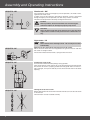
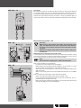
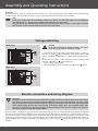
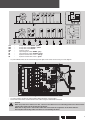
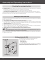
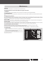
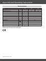
A50 / A70
en
Assembly and Operating Instructions
Direct Mount Drives
Important information for:
• Fitters
• Electricians
• Users
Please forward accordingly!
These instructions must be kept for future reference.
Assembly and Operating Instructions
Table of Contents
Intended use............................................................................................................................................................... 2
Warranty...................................................................................................................................................................... 2
Safety information........................................................................................................................................................ 3
Product Overview and Dimensions................................................................................................................................. 4
Installation................................................................................................................................................................... 5
Emergency manual operation........................................................................................................................................ 5
Voltage switching......................................................................................................................................................... 8
Electric connection and wiring diagram.......................................................................................................................... 8
Checking the running direction.................................................................................................................................... 10
Setting the limit switches............................................................................................................................................ 10
Sliding clutch AK+RK.................................................................................................................................................. 10
Maintenance..............................................................................................................................................................11
Technical data........................................................................................................................................................... 12
Intended use
The A50/A70 direct mount drives are intended exclusively for indoors for driving sectional doors, with a safety distance that is
balanced by springs or counterweight. It is necessary to use special connecting cables for outside use or PVC-cables have
to be guided through tubular cable protections.
If the direct mount drives are used for purposes other than the above-mentioned ones, e.g. for roller doors or vertical lift gates
or for external installation or if modifications are made to the equipment which affect the safety of the system, the manufacturer or supplier accepts no liability for damages arising to persons or to property, nor for any consequential damages.
For operation of the system or repair, the operating instructions must be observed. In the event of improper handling, the manufacturer or supplier accepts no liability for damages arising to persons or to property, nor for any consequential damages.
Warranty
Structural modifications and incorrect installation which are not in accordance with these and our other instructions can result
in serious injuries, e.g. crushing of limbs. Therefore, structural modifications should only be carried out with our prior approval
and in accordance with our instructions, particularly the information contained in these Assembly and Operating Instructions.
Any further processing of the products which does not comply with their intended use is not permitted.
The end product manufacturer and fitter have to ensure that all the current statutory, official regulations and, in particular,
EMC regulations are adhered to during utilisation of our products, especially with regard to end product assembly, installation
and customer advice.
2
Safety information
The following safety information and warnings serve to avert dangers and to avoid personal injury or damage to property.
Keep these instructions in a safe place.
Caution
Denotes a potentially hazardous situation. If this is not avoided, injuries may
result
Attention
Denotes a potentially hazardous situation. If this is not avoided, the product
or something in its vicinity may be damaged.
Note
Denotes user tips and other useful information.
Important safety information.
Caution! Non-observance can lead to serious injuries.
Comply with the safety information of EN 12453 and EN 12445
• Work on the electrical installation, the electric or electronic systems and devices may only be carried
out by qualified experts.
• When electrical or electronic systems and devices are operated, certain components are under a potentially dangerous electrical voltage. In the event of unauthorised intervention or non-observance of
warning, physical injuries or damage to property may result.
• All applicable norms and provisions for electrical installation are to be followed.
• Only spare parts, tools and additional equipment approved by the firm Becker may be used.
• In the case of products obtained from other sources or unauthorised modifications to accessories, the
manufacturer or supplier accepts no liability for damages arising to persons or to property, nor for any
consequential damages.
• The limits indicated in the technical data may not be exceeded.
• If the drive is mounted at a height of less than 2.50 m, a protective hood is required, as touching the
surface of the motor can cause burns.
• A sufficient safe distance is to be observed between drive and combustible materials.
• When the safety switches S1F, S2F, S3F or S4F are opened, the control used must switch off the drive.
• The door has to be protected by fixed buffers to prevent accidental derailing from the guides.
• The door system must be secured against crashing down.
• When using a direct mount drive with a disconnecting clutch (AK), it is imperative to install a safety
device (anti-drop device in case of a spring fracture) to prevent the door from falling down.
• For direct mount drives with light chain (LK) or hand crank (HK) it must be ensured that in the event
of spring fracture or failure of the counterweight the holding torque on the drive is less than the
static holding torque indicated in the technical data.
If this is not the case, a safety device (anti-drop device) has to be installed when using a direct
mount drive to prevent the door from falling down.
3
Assembly and Operating Instructions
Product Overview and Dimensions
All dimensions in mm.
Hollow shaft
(valid for all types)
6.35
27.6
M8
85
A50-HK / A70-HK
Direct mount drive
with hand crank
25.45
A50-LK / A70-LK
Direct mount drive with light chain
A50-AK
Direct mount drive with
disconnecting clutch
A50 - AK+RK
Direct mount drive with
sliding clutch and disconnecting clutch
4
Installation
After installation of the sectional door and counterbalancing in compliance with the regulations, the door has to be counterbalanced in every position.
You can check whether it is properly counterbalanced by opening and closing the door manually.
Attention
The direct mount drive must be mounted on a vibration reducing mounting or torque supporting plate
with adequate stability. In the event of non-observance, the product or something in its vicinity may be
damaged.
Before the direct mount drive is placed on the door shaft, this is to be lubricated in the range of the drive.
Feather key for 1“ tubular shaft
Feather key for 1“ solid
shaft
Attention
Only the feather keys enclosed may
be used.
After fastening, the feather key is to
be secured to prevent shifting. Use 2
DIN 3017 - A - 20-32 x 9 - W1 - 2 hose
clamps to secure the feather keys.
The hose clamps are to be fixed to the
door shaft to the left and right of the
drive.
Emergency manual operation
With the aid of emergency manual operation, the door can be opened or closed in the event of a power failure.
Attention
Before emergency manual operation is used, the door system must be disconnected from the power
supply. Manual emergency operation is only allowed with the motor turned off, via hand crank and to be
handled by the service technician or instructed personnel.
Note
The door may not be moved beyond the final positions, since otherwise a safety limit switch (S1F/S2F) is
reached. Electrical operation of the door system is only possible again when the safety limit switch (S1F/
S2F) is “released” by means of emergency manual operation.
For emergency manual operation, 3 different systems are available:
• Hand crank - HK
• Light chain - LK
• Disconnecting clutch - AK
5
Assembly and Operating Instructions
A50/A70 - HK
Hand crank - HK
First remove the cover. For emergency manual operation, the hand crank is
applied to the motor shaft.
In order to ensure that electrical operation of the door system is prevented
during emergency manual operation, the S3F safety switch is activated.
The door can be opened or closed by turning the hand crank.
Caution
After operation, the hand crank must be removed again,
otherwise injuries or damage to property may result.
Attention
After the hand crank has been removed, the cover has to be
replaced in accordance with protection class IP54 of the casing.
Light chain - LK
Note
Direct mount drives with light chain - LK can only be mounted
horizontally.
A50/A70 - LK
Mounting of the chain wheel with integrated chain guard.
Mount the chain wheel with the integrated chain guard so that the side with
the sticker is facing the drive.
Fix the chain wheel with flat washer, spring washer and screw.
A50/A70 - LK
Introduction of the chain
Turn the chain wheel with the openings facing upwards.
Take one end of the chain and put this in the left opening of the chain guard.
Ensure that the chain is properly positioned in the guide. Then turn the casing to the right, until you are able to pull out the end of the chain in the other
opening.
A50/A70 - LK
Joining the ends of the chain
Before joining the ends of the chain with the chain lock, ensure that the chain
is not twisted.
The chain lock must be fastened carefully.
6
A50/A70 - LK
Operation
By pulling the chain on the relevant side the door can be manually opened
or closed. In order to ensure that electrical operation of the door system is
prevented during emergency manual operation, the S3F safety switch is activated. After operation ensure that the chain is “freely suspended” again so
that the S3F safety switch is released and electrical operation is now possible.
Disconnecting clutch - AK
A50 - AK
Attention
When using a direct mount drive with a disconnecting clutch
(AK), it is imperative to install a safety device (anti-drop device in case of a spring fracture) to prevent the door from falling down.
Operation is only possible when the door system is fully counterbalanced.
Mounting of the chain wheel and chain guard
2 chain wheels are enclosed with the drive. If the door shaft protrudes a long
way from the drive, the small plastic chain wheel must be used. If this is not the
case, using the larger metal chain wheel is recommended.
Note
Ensure that the coupling pin is still on the left buffer.
Door shaft protrudes far from the drive:
A50 - AK
• Put the plastic chain wheel on the coupling pin.
• Mount the plastic chain wheel with locating disc (1), flat washer (2), screw
(3). Ensure that the coupling pin is still in the left buffer.
• Mount the chain so that approx. 3 chain links are suspended freely on the
right-hand side.
• Mount small chain guard on the chain wheel hub until there is an audible
click.
Door shaft does not protrude (or not much) from the drive:
• Mount the large chain guard and fix with the slotted screw.
• Insert the metal chain wheel with chain so that 3 or 4 chain links are suspended freely on the right-hand side.
• Mount metal chain wheel with locating disc, flat washer and screw. Ensure
that the coupling pin is still in the left buffer.
7
Assembly and Operating Instructions
Operation
By pulling the chain, the drive is decoupled from the door shaft. The counterbalanced sectional door can now be opened or
closed manually. After operation, the drive must be coupled again by pulling the other end of the chain.
Note
It should be ensured that the lower final position of the door is set so that the cables for suspending the
door remain taut, i.e. that the entire weight of the door hangs on the cables.
This guarantees the smooth running of the disconnecting clutch. False settings (slack rope) in the lower
final position prevent smooth running of the disconnecting clutch.
Voltage switching
A50 / A70
Caution
Before the beginning of voltage switching, the drive is
to be disconnected from the power supply.
3~
400V
It is possible to operate the direct mount drive using a 3~ 400 V (
-STAR) or 3~ 230 V ( -DELTA) connection to the power supply. Upon
delivery, the drive is switched for a 3~ 400 V supply in STAR connection.
For operation using the 3~ 230 V supply, the drive must be changed
over from a -STAR to a -DELTA connection:
1. Remove the 3 x 230 V sticker
2. Change over to the 6-pole connector from -STAR to -DELTA.
A50 / A70
3~
230V
Electric connection and wiring diagram
Attention
The electric connection may only be carried out by a skilled electrician! Please observe the documentation on the control to be used and the applicable VDE norms! For all connection work, the door system
must be properly disconnected from the power supply by removing the CE-connector/switching off the
main switch! Please observe the technical data of the direct mount drive. The maximum values given
must not be exceeded! In particular, the door system protection provided by the customer has to be carried out in accordance with the technical data!
Only use original 12-core or 18-core control wires approved by the manufacturer when connecting the direct mount drive to
the control. The control wire is pluggable. To ensure that the tension relief and the protection class are guaranteed, the screws
must not be loosened. In order to plug in the 18-core control wire the 10-pole jumper plug in the drive must be removed. The
connectors are protected against reverse polarity and there is an audible click when they engage. The green and yellow protective conductor wires must be connected to the designated push-on connector . Please ensure that it clicks into place
properly.
8
S1F
S2F
S3F
S4F
S5
S6
S7
S8
-
-
-
-
-
-
-
-
Safety limit switch OPEN - yellow
Safety limit switch CLOSE - yellow
Safety limit switch HK/LK
Thermal switch
Operating limit switch OPEN - grey
Operating limit switch CLOSE - black
Special function limit switch - orange
Special function limit switch - green
• Lay the individual wires of the control wiring to the right of the centre of the casing as in the diagram.
• Lay the protective conductor (green/yellow) below the black control cables.
• Fasten the control wires to the internal motor cable using the cable binder enclosed.
Caution
When the protective conductor is laid, care must be taken not to accidentally pull out the cable and disconnect the contact of the protective conductor.
When the casing cover is closed the cables must not touch the cogwheels of the limit switches.
Then lay the connecting cable so that this is not touching the drive.
9
Assembly and Operating Instructions
Checking the running direction
The turning direction of the drive depends on the connection of the 3 network phases to the control and has to be checked
first. Proceed as follows:
• Bring the door to a half-opened position by means of emergency manual operation.
• Put the CE connector of the control in the socket, or switch the main switch of the control on.
• Ensure that the control is in deadman mode.
• Check with the UP and DOWN buttons whether the Running direction of the door corresponds to the buttons pressed.
If the Running direction of the door does not correspond to the commands given, swap two of the phases, as described in the
operating instructions of the control. Then check the running direction again.
Setting the limit switches
The door drive is equipped with 6 cam limit switches. All trip cams have 12 locking levels. Ensure that the control is in deadman
operation. Proceed as follows:
1. Turn all 6 trip cams so that they are not in the path the door travels along.
2. Lower the door with the DOWN button of the control until just before the lower final position.
3. Turn the black trip cam S6 “CLOSE” until you can easily reach the fine adjustment screw. Now set the cam using the setting
screw (slot) so that it is activated. Raise and lower the door slightly until the limit switch stops the door. Adjust the setting
accordingly if necessary.
4. Now raise the door to just before the upper final position.
5. Now set the grey trip cam S5 “OPEN” following the same procedure as in 3 above.
6. Now set the yellow safety trip cams S1F “UP” and S2F “DOWN” using the same procedure as with the operating limit
switches S5 “OPEN” and S6 “CLOSE” but set slightly behind the operating cams.
7. The two function trip cams S7 (orange) and S8 (green) can be set accordingly if required.
8. The limit switches are set now. Verify their settings by running the door for a full cycle.
Note
If the orange function trip cam S7 is used as a prelimit switch for the breaking capacity of the door, it can
only switch at a maximum of 5 cm above the ground; EN12445.
Replace the casing cover of the limit switches. Ensure that the seal and seal groove are clean and the cover is replaced properly. Tighten the bolts correctly.
Sliding clutch AK+RK
A50 - AK+RK
10
The sliding clutch serves to limit the maximum drive torque.
Only set the sliding clutch when not in operation:
• Remove cover (1).
• Secure spiral shaft (2).
• Loosen screw (3).
• Turn threaded pin (4).
In a clockwise direction the torque is increased, in an anticlockwise
direction it is decreased. The maximum setting is 12 revolutions. After
setting the torque, tighten locknut and replace the cover.
Maintenance
Gearbox:
The gearbox is lubricated for its full lifetime and is maintenance-free.
The following tests are to be carried out at regular intervals:
1. Fixtures:
All fastening screws are to be checked to ensure that they are secured in place and in good condition.
2. Counterbalance:
The counterbalance, or the spring tension is to be checked. The sectional door should be fully counterbalanced in each position.
3. Safety limit switches:
The safety limit switches S1F, S2F and S3F are to be tested to ensure they are in working order and to test their switch-off
point. Please follow the relevant operating instructions of the door control. Operation of the safety limit switches is to be
checked for its continuity (loop must be closed) in accordance with the wiring diagram.
For S1F / OPEN
Move to the upper final position. Using emergency manual operation, move up further, to the point where no damage occurs.
Now check whether the safety limit switch S1F has been reached and opened.
For S2F / CLOSE
Move to the lower final position. Using emergency manual operation, move down further, until there is no strain on the cable
for suspending the door. Now check whether the safety limit switch S2F has been reached and opened.
For S3F (only applies to HK and LK drives)
Before the safety limit switch S3F is checked, the door system must be disconnected from the power supply.
Put the hand crank on the motor shaft or pull the chain and keep this taut.
The safety limit switch S3F is to be checked in accordance with the wiring diagram. It should not be in operation.
4. Toothed belt
1. Check the toothed belt to ensure there is sufficient tension.
2. Carry out a visual inspection of the toothed belt across
the entire distance travelled by the door.
Pay attention to the condition of the toothed belt (it must not
be spliced or perished).
Toothed belt
11
Assembly and Operating Instructions
Technical data
Type
Take-off torque
Nominal current
Performance factor cos j
Number of revolutions in take-off
Diameter of hollow shaft
Operating voltage
Frequency
Control voltage
Control current
Insulation class
Thermal switch
Operating type
Protection class
Limit switch range
Static holding torque
Installation safety
Permissible surrounding temperature
Weight *) (ca.)
T
I
cos j
n
U
f
S3
IP
*) The LK version weighs an extra 0.5 kg.
Deviations are possible with identical drives or special drives
The specifications on the type plate are always valid.
Subject to technical changes
12
Unit
Nm
A
min-1
mm
V
Hz
V
A
°C
%
revolutions
Nm
A
°C
kg
A50
50
2.5/1.4
0.8
A70
70
3.8/2.2
0.78
25
25.4
3~ 230/400
50
24 DC / 230 AC
max. 5 A AC-1
H
170
40
54
13
300
3x 10 A T
-20 to +40
10
13
Assembly and Operating Instructions
14
15
2340 300 026 0c
08/09
Becker-Antriebe GmbH
35764 Sinn/Germany
www.becker-antriebe.com