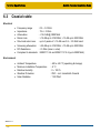
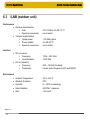
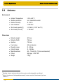
1
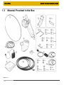
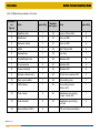
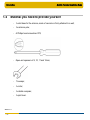
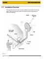
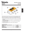
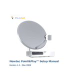
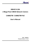
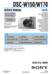
Satellite Terminal Installation Guide Release 2.2 ref. nr.: 35239 Satellite Terminal Installation Guide Introduction TABLE OF CONTENTS Table of Contents .................................................................................................... 2 version 1.0 -2- 1 Introduction ................................................................................................... 4 1.1 About this Guide .............................................................................................. 4 1.2 Safety Precautions .......................................................................................... 5 1.3 Material Provided in the Box ........................................................................... 8 1.4 Material you need to provide yourself ........................................................... 10 1.5 Installation Overview ..................................................................................... 11 2 Antenna Installation .................................................................................... 12 2.1 Step 1: Choosing a Suitable Location ........................................................... 12 2.2 Step 2: Mounting the Antenna Pole .............................................................. 13 2.3 Step 3: Installing the earthing kit on the masthead ....................................... 14 2.4 Step 4: Setting the Elevation Angle............................................................... 16 2.5 Step 5: Mounting the Antenna ....................................................................... 18 2.6 Step 6: Connecting the Equipment ............................................................... 22 3 Terminal Installation ................................................................................... 27 3.1 Step 1: Select Outdoor Unit .......................................................................... 28 3.2 Step 2: Select Spot Beam ............................................................................. 29 3.3 Step 3: Pointing your antenna ....................................................................... 30 3.4 Step 4: Software Download ........................................................................... 41 3.5 Step 5: Validation of the Installation .............................................................. 42 3.6 Finish Installation........................................................................................... 47 4 Restart Installation ...................................................................................... 49 Introduction version 1.0 -3- Satellite Terminal Installation Guide 5 Troubleshooting Guide ............................................................................... 50 5.1 Spot Beam / Outdoor Unit Issues.................................................................. 50 5.2 Antenna Pointing Issues ............................................................................... 51 5.3 Installation Validation Issues ......................................................................... 54 6 Terminal Specifications .............................................................................. 60 6.1 Modem (indoor unit) ...................................................................................... 60 6.2 Coaxial cable ................................................................................................. 61 6.3 iLNB (outdoor unit) ........................................................................................ 62 6.4 Antenna ......................................................................................................... 63 Satellite Terminal Installation Guide Introduction 1 INTRODUCTION 1.1 About this Guide This guide provides a step-by-step procedure to install your satellite terminal. Before installing Before starting to install your satellite terminal, it is important to read the following sections: • • • Safety precautions (page 5); Material provided in the box (page 8); Material you need to provide yourself (page 10). Follow the entire procedure When installing the antenna, it is important that you follow the entire procedure step-bystep. Skipping one or more sections might lead to incomplete or incorrect installation and/or operation of your satellite terminal. Related documentation • • The MDM2200 User Manual, describing the features and the web interface of the modem (available on the CD included in the box); The antenna pointing information, which contains the geographical pointing data. This information is provided by your Service Provider, either as a booklet included in the box, either in a different format. Copyright © 2012 version 1.0 -4- Satellite Terminal Installation Guide Introduction 1.2 Safety Precautions This section lists the safety precautions to follow when installing the antenna. Safety precautions are grouped into warnings and cautions. Local regulations Always install the satellite terminal in accordance with applicable local regulations. Consult with a licensed electrician if in any doubt. 1.2.1 Warnings A warning refers to an action or situation that could result in injury, long term health hazard or death if you do not follow the instructions. Antenna • RF radiation hazard: Hazardous electromagnetic field levels are generated in the area between the antenna reflector and the iLNB feed horn and the area around the antenna during transmission. Do not place any part of your body in that zone while the system is on. Take the necessary precautions to prevent access to the antenna by children or unauthorized persons. Refer to the ICNIRP (International Commission on Non-Ionizing Radiation Protection) guidelines for more details. Modem • • • • version 1.0 -5- There are no user-serviceable parts in the modem. Do not attempt to open the system. There is a risk of electrical shock that may result in injury and death. The modem should only be opened by a technician trained and certified to service the product. To prevent the risk of fire or electrical shock, do not expose the indoor equipment to rain, liquids or moisture. Do not place any objects containing liquids (e.g. glasses, vases) on the system. Do not install the antenna and modem when there is a risk of thunderstorm or lightning activity in the area. Do not use the in-line power supply power cord when damaged in any way. Satellite Terminal Installation Guide Introduction 1.2.2 Cautions A caution refers to an action or situation that could result in equipment damage or destruction if you do not follow the instructions. Modem • • • • • • • version 1.0 -6- Always use the in-line power supply included with the modem. Using a different power supply may cause equipment damage. To ensure regulatory and safety compliance, use only the provided power and interface cables or cables which conform to the specifications within this manual. Do not open the unit. Do not perform any servicing other than described in the installation instructions. Refer all other servicing to qualified service professionals. Static electricity can damage the modem. To avoid damaging the modem with static electricity, always touch the grounded coaxial cable connector prior to touching any other part of the system. To clean the outside of the unit, use a clean, dry cloth. To avoid equipment damage, never clean the system using fluids, detergents or chemicals. Do not use pressurised air to remove dust from the unit. Install an AC surge arrestor in the AC outlet to which the modem is connected to avoid damage to the equipment from lightning strikes and other electrical surges. To prevent overheating, do not block the ventilation holes on the sides and top of the unit. Satellite Terminal Installation Guide Introduction Antenna • • • • • Due to the wind pressure equivalent area of the antenna, do not make an installation in bad weather conditions; Secure tight all parts to avoid any potential danger to persons and surroundings; If faced with a critical situation in which personal safety is in jeopardy, do not try to keep hold of the antenna; Make sure a minimum distance of 6 metres (20 feet) separates the antenna from any power line; Before digging, in case of need for a penetrating antenna mast, contact your local authority to check for information regarding any underground cables and (power) utility line(s). In some countries, authorisation is needed for satellite reflector installation. Call your local authorities in case of doubt. Point&Play® tool • version 1.0 -7- To avoid damage to your hearing, ensure that the volume of the Point&Play® tool is not set too loudly. Introduction 1.3 Material Provided in the Box version 1.0 -8- Satellite Terminal Installation Guide Satellite Terminal Installation Guide Introduction List of Material provided in the box: Number on figure quantity Number on figure Item quantity 1 Satellite dish 1 15 Screw 18mm M5 2 2 Masthead 1 16 Hex nut M8 4 3 Network cable 1 17 Hex nut M6 4 4 iLNB 1 18 Bolt 10mm M6 4 5 Headphone 1 19 Hex key 1 6 Point&Play® tool 1 20 Washer M8 4 7 F-connectors 3 21 Washer M6 4 8 Power adapter 1 22 Washer M4 2 9 Modem (stand incl.) 1 23 Tooth lock washer M4 2 10 Twin coax cable 1 24 Grounding wire 1 11 iLNB clamp 1 25 Grounding screw 10mm M4 1 12 Pole clamp 2 26 Masthead grounding screw 16mm M5 1 13 Pole bracket 2 27 Masthead grounding nut M5 2 14 Screw 25mm M3.5 2 version 1.0 -9- Item CD and documentation Satellite Terminal Installation Guide Introduction 1.4 Material you need to provide yourself version 1.0 - 10 - - A solid base for the antenna, made of concrete or firmly attached to a wall; - An antenna pole; - A Phillips head screwdriver PZ2; - Open-end spanners of 8, 10, 11 and 12mm; - Tie-wraps; - A cutter; - A reliable compass; - A spirit level. Introduction 1.5 Satellite Terminal Installation Guide Installation Overview The image below shows the result of a typical installation as described in the following pages. Please read these pages carefully and follow the step-by-step procedure to execute the installation. version 1.0 - 11 - Antenna Installation Satellite Terminal Installation Guide 2 ANTENNA INSTALLATION 2.1 Step 1: Choosing a Suitable Location Outdoors: antenna & iLNB • • • When setting up the antenna base, take into account the orientation of the antenna. Orientation data is provided by your Service Provider. The antenna must have a clear view towards the satellite (without any buildings, trees,... that may hinder the signal). To connect the iLNB to the Modem, use a coax cable. You can use the provided coax cable or a coax cable with the same specifications as described in section 6. The coax cable included in the box is 30 metres long. Indoors: Modem and computer Put the Modem indoors in a dry room and connect to: • • • The antenna (with the coax cable); Your computer (with a network cable). Use the network cable provided in the box or a cable of your choice (for example if you need a longer cable to connect the modem to your computer); A wall outlet (with the power adapter provided in the box). Power adapter specifications: universal input range 100-240 Volt, 50-60Hz. These steps are described further in this document. version 1.0 - 12 - Antenna Installation 2.2 Satellite Terminal Installation Guide Step 2: Mounting the Antenna Pole Antenna pole requirements • • • The antenna pole must be installed on a solid base and made of galvanised steel; Minimum diameter: 45mm (60mm recommended); Maximum diameter: 70mm. When fixing the antenna pole to the base, use a spirit level to make sure the antenna pole stands in a vertical upright position. version 1.0 - 13 - Antenna Installation 2.3 Satellite Terminal Installation Guide Step 3: Installing the earthing kit on the masthead 1. Unfold the feed arm and fix its position by tightening the two pre-mounted screws on the masthead. version 1.0 - 14 - Antenna Installation Satellite Terminal Installation Guide 2. Take the M5 grounding screw from the grounding kit and fix it to the masthead from the inside, as shown in the picture below. Verify that the earthing symbol is present next to the hole. 3. Take one of the M5 masthead grounding nuts, and tighten it using a Philips (PZ2) and a 8mm spanner. This completes the installation of the earthing kit on the masthead. The remaining items of the grounding kit will be used later on, when grounding the iLNB. You can now proceed to the next step: setting the elevation angle. version 1.0 - 15 - Antenna Installation 2.4 Satellite Terminal Installation Guide Step 4: Setting the Elevation Angle 1. Use the antenna pointing information provided by your Service Provider to look up the elevation angle that applies to your location, or to the city closest to your location. 2. Loosen all elevation nuts (1) and (2) (three nuts in total) on the masthead using a 10mm open spanner. 3. Make sure the elevation fine adjustment bolt (3) is pointing to the middle position (arrow pointing to the middle marker). If not, adjust with a 10mm spanner or use the hex key included until this is the case. version 1.0 - 16 - Antenna Installation Satellite Terminal Installation Guide 4. Using the elevation scale (4) on the left side of the masthead, set the elevation angle to the value you have found in the antenna pointing information, and tighten nut (2) to fix the elevation angle. Note: the elevation scale is located on the left side of the masthead, nut (2) is located on the right side of the masthead. Note: this nut must be tightened strongly, as the elevation position should not move when mounting the antenna later on. This completes the setting of the elevation angle. The two other elevation nuts (1) (one on either side of the masthead) should not yet be tightened, as some finepointing still needs to be done later on. You can now proceed to the next step. version 1.0 - 17 - Satellite Terminal Installation Guide Antenna Installation 2.5 Step 5: Mounting the Antenna Now the remaining parts of the antenna can be mounted. For easy installation, please follow the sequence as described. 1. First mount the masthead to the antenna pole. The clamps, pole brackets, M8 nuts and washers can be found in the accessory bag. Hand-tighten the nuts making sure the masthead can still be rotated around the pole. version 1.0 - 18 - Antenna Installation Satellite Terminal Installation Guide 2. Secondly, mount the antenna dish onto the masthead. The four M6 bolts (10mm), nuts and washers can be found in the accessory bag. version 1.0 - 19 - Antenna Installation Satellite Terminal Installation Guide 3. Thirdly, mount the iLNB clamp onto the feed arm. The two M5 screws (18mm) can be found in the accessory bag. version 1.0 - 20 - Antenna Installation Satellite Terminal Installation Guide 4. Next mount the iLNB into the clamp. Ensure the clasp at the bottom of the iLNB fits into the notch of the clamp. The two M3.5 screws (25mm) can be found in the accessory bag. This completes mounting the antenna. You can now proceed to the next step. version 1.0 - 21 - Antenna Installation 2.6 2.6.1 Satellite Terminal Installation Guide Step 6: Connecting the Equipment Preparing the Coax Cable The twin coax cable is delivered with two premounted waterproof connectors on one side. This is the outdoor end of the cable. The other side of the cable has no connectors attached yet, which allows the length of the cable to be reduced (e.g. if required for practical reasons). This is the indoor end of the cable. Execute the following steps to attach the F-connectors to the indoor end of the cable. You will need a cutter (and possibly pliers) to connect the F-connectors. 1. Strip the coax cable as shown below. Do not remove the aluminium foil or fold it back. version 1.0 - 22 - Antenna Installation Satellite Terminal Installation Guide 2. Fold the wire shielding backwards over the cable jacket. 3. Cut away the plastic shield. Screw the F-connector to the wire by hand. 4. The result should resemble like the figure below: Repeat this procedure for the second F-connector. version 1.0 - 23 - Antenna Installation 2.6.2 Satellite Terminal Installation Guide Grounding the iLNB 1. Connect the grounding wire to the iLNB as shown in the figure below, using the washers and M4 grounding screw which can be found in the grounding kit bag. 2. Connect the other side of the grounding wire to the grounding screw on the masthead as shown in the figure below. 3. The masthead needs to be grounded according to local regulations. Consult with a licensed electrician if in any doubt. version 1.0 - 24 - Antenna Installation 2.6.3 Satellite Terminal Installation Guide Connecting the Modem to the iLNB To connect the modem to the iLNB: 1. Identify the TX and RX marks on the twin coax cable. These marks are printed on the cable every 50cm. 2. Put the TX and RX connectors in the appropriate TX and RX jacks on the iLNB. Make sure to use the premounted and waterproof outdoor connectors. Note: the TX cable must to be disconnected again later when pointing the antenna. 3. Put the indoor TX and RX connectors in the appropriate TX and RX jacks on the modem. Use an 11mm spanner to fasten the connectors on the modem. version 1.0 - 25 - Antenna Installation 2.6.4 Satellite Terminal Installation Guide Connecting the Modem to your Computer 1. Plug the network cable in the modem’s and your computer’s Ethernet ports. Use the network cable provided in the box or a cable of your choice. 2. Connect the power adapter provided in the box gently to the modem and a wall outlet. The result should resemble like the figure below. The modem itself can be installed in three ways (as illustrated in the picture below): • • • version 1.0 - 26 - Wall mounted (Note: screws for wall mount installation are not included); Horizontal; Vertical (mounted on the included stand). Satellite Terminal Installation Guide Terminal Installation 3 TERMINAL INSTALLATION Before you start: The procedure below assumes: - that your computer is DHCP enabled; - that you will connect a single computer to the modem. If this is not the case or if you have another configuration, you will find more information in the MDM2200 User Manual. You need to access the GUI (Graphical User Interface) of the modem. • • • • Make sure the modem is turned on and properly connected to your computer (with a network cable). On your computer, start your internet browser (for example, Internet Explorer, Chrome, Mozilla Firefox, Opera, Safari...). The GUI is located on the modem itself. You do not need an internet connection to access it. Type 192.168.1.1 in the address bar of the browser and press Enter. The terminal installation page opens. Follow the sequence of installation steps as described in the next sections. If the software version of your modem is not 2.2.x.y (where x and y can be any number), the installation procedure can differ from what is described in this manual. Please contact your Service Provider in case of problems. The software version is shown on the installation page. version 1.0 - 27 - Satellite Terminal Installation Guide Terminal Installation 3.1 Step 1: Select Outdoor Unit • Click version 1.0 - 28 - Select the outdoor unit type corresponding to your antenna size and iLNB. to continue. Satellite Terminal Installation Guide Terminal Installation 3.2 Step 2: Select Spot Beam • Select the beam identifier corresponding to your location as indicated in the antenna pointing information provided by your Service Provider. • Click to continue. If an error message appears while executing this step, then go to section 5 Troubleshooting Guide. version 1.0 - 29 - Satellite Terminal Installation Guide Terminal Installation 3.3 Step 3: Pointing your antenna Do not stand in front of the iLNB of the antenna dish during pointing. Keep the space between the iLNB and the antenna dish clear. 3.3.1 Enabling Pointing Mode on the Modem version 1.0 - 30 - • If only one pointing carrier has been pre-configured, the following screen is shown: • If two pointing carriers have been pre-configured, keep the pre-selected carrier. If pointing fails during the procedure, you will need to repeat this step with the other pointing carrier. Terminal Installation Satellite Terminal Installation Guide Click to start the pointing procedure and proceed to the next section: Setting up the Point&Play Tool. to skip the pointing procedure (use if the antenna was already Click correctly pointed). version 1.0 - 31 - Satellite Terminal Installation Guide Terminal Installation 3.3.2 Setting up the Point&Play Tool 3.3.2.1 Introduction The Point&Play tool helps you to point the antenna correctly. During the pointing procedure, the Point&Play tool can produce various sounds, each having a specific meaning described below. You will thus need to put on the headphone whenever needed during the pointing procedure. Ensure that the volume of the Point&Play® tool is not set too loudly, otherwise damage to your hearing may occur. Possible tones are: - High uninterrupted tone (correct tone) The antenna points to the correct satellite and is receiving the strongest signal: you have the optimal pointing position. - Higher interrupted tone The antenna points to the correct satellite but does not receive the strongest signal so far. As soon as you hear this tone, you are sure that the antenna points to the correct satellite. - Low uninterrupted tone The antenna points to a wrong satellite and receives the strongest signal so far. - Very low uninterrupted tone The antenna is not pointing to a satellite and has not been pointed to the correct satellite yet. version 1.0 - 32 - Terminal Installation 3.3.2.2 Satellite Terminal Installation Guide Using the Point&Play Tool To use the Point&Play tool: 1. Remove the TX connector from the iLNB and connect it to the Point&Play tool. 2. Connect the earphone to the Point&Play tool. Make sure the Point&Play tool is still switched off. version 1.0 - 33 - Terminal Installation 3.3.3 Satellite Terminal Installation Guide Rough Pointing Important note: Whenever the procedure tells you to loosen a securing bolt or nut, make sure it is just loose enough to allow the corresponding element to move freely. 3.3.3.1 Vertical Pointing The correct elevation angle was already set during the installation of the antenna. Verify that the elevation angle of the masthead still corresponds to the value you have found in the antenna pointing information, and that it did not change during the assembly of the antenna (e.g. due to the weight of the antenna dish). Adjust if necessary. version 1.0 - 34 - Satellite Terminal Installation Guide Terminal Installation 3.3.3.2 Horizontal Pointing Before starting the horizontal pointing (azimuth), verify that the azimuth fine adjust bolt (1) is in the middle position. Adjust with a 10mm spanner if necessary. Note: for clarity, the antenna dish is not shown in the diagram below. Switch on the Point&Play tool by slowly turning the volume wheel until the green LED illuminates. Put on the earphone and adjust the volume if necessary. Now the actual pointing procedure can start. No Tone Check if the battery of the Point&Play tool is not dead. version 1.0 - 35 - Satellite Terminal Installation Guide Terminal Installation 1. Loosen the four M8 bracket nuts (2). 2. You can now move the antenna horizontally. Set the antenna to the azimuth angle that applies to your location, or to the city closest to your location. This value can be found in the antenna pointing information provided by your Service Provider. Use a compass if required. Attention: for correct functioning of the compass, do not use it closer than 1.5 meter from metal parts. 3. Slowly move the dish horizontally until you hear the highest possible continuous pitch tone (detection of the correct satellite). Make sure you position the antenna in the middle of this highest tone range. 4. Secure the four M8 bracket nuts (2) using a 12mm spanner. Do this in an alternating sequence in order to keep the highest pitch tone. If you do not hear a high pitch tone, refer to the Troubleshooting Guide (section 5). version 1.0 - 36 - Terminal Installation 3.3.4 Satellite Terminal Installation Guide Optimise Vertical Pointing (Elevation) 1. Loosen the two elevation bolts (1) (one on either side of the masthead). Note: for clarity, the antenna dish is not shown on the diagram below. 2. Optimise the elevation setting by rotating the elevation fine adjust bolt (2), using a 10mm spanner, until the Point&Play tool produces the highest continuous pitch tone. 3. Secure the two elevation bolts (1) in an alternating manner to keep the highest pitch tone. version 1.0 - 37 - Terminal Installation 3.3.5 Satellite Terminal Installation Guide Optimise Horizontal Pointing (Azimuth) 1. Loosen the four azimuth bolts (1) (two at the top of the masthead, two at the bottom). 2. Optimise the azimuth setting by rotating the azimuth fine adjust bolt (2), using a 10mm spanner, until the Point&Play tool produces the highest continuous pitch tone. 3. Secure the four azimuth bolts (1) in an alternating manner to keep the highest pitch tone. version 1.0 - 38 - Terminal Installation 3.3.6 Satellite Terminal Installation Guide Checking the Pointing Perform the following checks to make sure the antenna will resist external movements (wind...): 1. Make sure all bolts are tightly secured. 2. Briefly place your hand between the iLNB and the dish. As soon as you remove your hand, you need to hear the continuous high pitch tone again. 3. Apply some pressure on the antenna to make the edges move about 3cm on the left hand side, right hand side and at the top, then release it. If the antenna is still pointed correctly, you will hear the high pitch tone again. If not, repeat the pointing procedure from the section 3.3.3 Rough Pointing. 4. When the antenna is correctly pointed, the message Correct satellite – pointed optimally appears on the screen of your computer, as shown below. You can now proceed to section 3.3.7 Finishing the Pointing. 5. When the antenna is not optimally pointed, the message Correct satellite – not pointed optimally is displayed on the screen of your computer, as shown in the following picture. Repeat the pointing procedure from the section 3.3.3 Rough Pointing. If the problem persists, refer to the Troubleshooting Guide (section 5). version 1.0 - 39 - Terminal Installation 3.3.7 Satellite Terminal Installation Guide Finishing the Pointing 1. Turn off the Point&Play tool 2. Remove the TX cable from the Point&Play tool and connect it to the iLNB. 3. Use tie-wraps to attach the cables to the feed arm. Make sure to leave some slack on the cables. The result is shown in the picture below: 4. Back at your computer, in the status page of the modem, click version 1.0 - 40 - Satellite Terminal Installation Guide Terminal Installation 3.4 Step 4: Software Download The modem continuously checks for software updates. • If the software is still up to date, this step is skipped automatically. You can proceed with step 5: Validation of the Installation. • If a newer software version is available, download will start automatically. - Once the download is complete, the new software is written to flash memory. - The modem reboots automatically. Now you can proceed with step 5 Validation of the Installation. You may need to refresh the page of your browser manually after the reboot. version 1.0 - 41 - Terminal Installation 3.5 Satellite Terminal Installation Guide Step 5: Validation of the Installation When step 4 is completed, the following screen is shown: The modem will now check if the quality of the installation needs to be validated. This depends on your Service Provider. • • version 1.0 - 42 - If validation of your terminal installation is required by your Service Provider, please proceed with this section and execute the following sequence of tasks. If validation of your terminal installation is not required by your Service Provider, this step is completed automatically and the terminal installation is finished. You can proceed to section 3.6 Finish Installation Satellite Terminal Installation Guide Terminal Installation 3.5.1 Accept Disclaimer As this validation procedure involves sensitive information such as geographical location of the terminal which is subject to legal restrictions, a disclaimer is presented. Please read the disclaimer message and indicate your acceptance by clicking 3.5.2 . Enter Location The validation of your installation is based on the geographical location of your terminal. There are 2 options to enter this information: • • 3.5.2.1 Option 1: enter your address; Option 2: enter your location’s latitude and longitude. Option 1: Enter your Address Enter the address where the terminal is located. At a minimum, your city and country are required. Alternatively you can also enter latitude and longitude values. version 1.0 - 43 - Terminal Installation Satellite Terminal Installation Guide A list of one or more matching locations is displayed. Select your address from the list to view your location on a map. If your address is not listed or no results are displayed, refer to the Troubleshooting Guide (section 5). version 1.0 - 44 - Satellite Terminal Installation Guide Terminal Installation The map is used to show the area of the selected location. Zooming in or out is not possible. Click to accept and proceed. If this is not your location, refer to the Troubleshooting Guide (section 5). 3.5.2.2 Option 2: Enter Latitude and Longitude Enter your location’s latitude and longitude. These values should be entered in degrees, minutes and seconds notation or in decimal form (using a dot as a separator). Positive latitude = NORTH, positive longitude = EAST. This option is used as a fallback mechanism in case Option 1 fails. No map is displayed when latitude or longitude values are entered using Option 2. Click version 1.0 - 45 - to continue or to return to the previous screen. Satellite Terminal Installation Guide Terminal Installation 3.5.3 Validation Once the location is confirmed, the validation begins. When validation is successful, click to proceed. If validation fails, go to section 5 Troubleshooting Guide. version 1.0 - 46 - Satellite Terminal Installation Guide Terminal Installation 3.6 Finish Installation • If step 5 (validation) was completed automatically (validation was not required by your Service Provider), the following screen is shown. Click version 1.0 - 47 - to go to the Status Page. Satellite Terminal Installation Guide Terminal Installation • If step 5 (validation) was successfully completed (validation was required by your Service Provider), the Status Page is shown. The terminal is ready for operation and all LED indicators on the status page are green. You are now ready to surf the internet. On-line registration may be required. Please check with your Service Provider. Please refer to the MDM2200 User Manual, describing the features and the web interface of the modem (available on the CD included in the box). version 1.0 - 48 - Satellite Terminal Installation Guide Restart Installation 4 RESTART INSTALLATION In some conditions (for example when moving the antenna to another location or upon request by your Service Provider), restarting the installation procedure is required. Select Terminal Installation in the left menu pane. Click to restart the complete installation procedure. Follow the sequence of steps as described in section 3 Terminal Installation. During the installation procedure, the terminal will not be operational. version 1.0 - 49 - Troubleshooting Guide Satellite Terminal Installation Guide 5 TROUBLESHOOTING GUIDE This chapter describes some possible error scenarios you might encounter during the installation or validation of your satellite terminal, and the possible solutions for these error conditions. If a problem persists, please contact your Service Provider for assistance. 5.1 Spot Beam / Outdoor Unit Issues 5.1.1 Spot Beam not Compatible 5.1.1.1 Problem Indication During beam selection, following screen is displayed indicating that the spot beam is not compatible with the outdoor unit: 5.1.1.2 Possible Reasons • • 5.1.1.3 An incorrect outdoor unit type is selected; An incorrect beam identifier is selected. Possible Solutions Select another beam identifier (if present) and click Select another outdoor unit type by clicking version 1.0 - 50 - . . Troubleshooting Guide 5.2 Antenna Pointing Issues 5.2.1 No Lock on Satellite / Low Pitch Tone 5.2.1.1 Problem Indication Satellite Terminal Installation Guide The Modem State on the Status page displays ‘No lock on satellite’. You keep hearing a low pitch tone through the Point&Play tool. 5.2.1.2 Possible Reasons • • • 5.2.1.3 There is no clear line of sight between the antenna and the satellite; An incorrect pointing carrier is selected; An incorrect beam identifier is selected. Possible Solutions Check if you have a clear line of sight, and no building, tree or other obstruction is blocking the path between the antenna and the satellite. Select a place with clear line of sight to set up the antenna. Also check if your compass is functioning correctly. version 1.0 - 51 - Troubleshooting Guide Satellite Terminal Installation Guide Click • If only one pointing carrier has been pre-configured, the following screen is shown. - Check with your Service Provider if the pointing carrier settings are still correct. Please refer to the User Manual how to verify the pointing carrier settings. • If an incorrect pointing carrier was selected, the following screen is shown: - Select the other pointing carrier from the dropdown list. Click to restart the pointing procedure (section 3.3.3). If the problem persists, you might have selected an incorrect beam. Click restart the beam selection procedure (section 3.1) version 1.0 - 52 - to Troubleshooting Guide 5.2.2 Wrong Satellite 5.2.2.1 Problem Indication Satellite Terminal Installation Guide The Modem State on the Status page displays ‘Wrong satellite’. You keep hearing a low pitch tone through the Point&Play tool. 5.2.2.2 Possible Reasons • 5.2.2.3 The antenna is not pointed correctly. Possible Solutions Check the Azimuth and Elevation settings. Perform the pointing procedure again (see section 3.3.3) until you receive the correct signal and hear a continuous high pitch tone. version 1.0 - 53 - Troubleshooting Guide 5.3 Installation Validation Issues 5.3.1 Terminal Location Not Listed 5.3.1.1 Problem Indication Satellite Terminal Installation Guide Based on the entered address, a list of matching locations is displayed during the first step of the validation procedure. The location of your terminal is not displayed in this list or no list is displayed at all. 5.3.1.2 Possible Reasons version 1.0 - 54 - • • • A typing mistake in the entered address; Not enough address details; An incorrect notation for latitude/longitude is used. The values must be separated by a comma or a space. The values should be entered in degrees, minutes and seconds notation or in decimal form (using a dot as separator). The hemisphere also needs to be specified. Examples of a correct syntax are shown below; • The map retrieval mechanism is out of order. Troubleshooting Guide 5.3.1.3 Satellite Terminal Installation Guide Possible Solutions Correct the typing mistake. Check if the entered address is spelled correctly; Enter full address details. At the minimum, your city and country are required, but you could add a postal code; Re-enter the values using the correct syntax; Use option 2 to enter the terminal location (section 3.5.2.2). version 1.0 - 55 - Satellite Terminal Installation Guide Troubleshooting Guide 5.3.2 Incorrect Syntax for Latitude/Longitude 5.3.2.1 Problem Indication When entering the latitude and longitude values (as described in section 3.5.2.2), the following error message can occur: 5.3.2.2 Possible Reasons An incorrect notation is used. A dot must be used as separator, not a comma. The hemisphere also needs to be specified. Positive longitude value = EAST, negative longitude value = WEST. Positive latitude value = NORTH, negative latitude value = SOUTH. 5.3.2.3 Possible Solutions Re-enter the values using the correct notation. version 1.0 - 56 - Troubleshooting Guide 5.3.3 Validation of Location Failed 5.3.3.1 Problem Indication Satellite Terminal Installation Guide During the location validation procedure, the following error message can occur: 5.3.3.2 Possible Reasons • • 5.3.3.3 An incorrect address has been entered; An incorrect beam identifier has been selected. Possible Solutions to restart your terminal installation from scratch (section 3). Ensure Click you select the correct beam (section 3.2) and enter the correct location (section 3.5.2). version 1.0 - 57 - Troubleshooting Guide Satellite Terminal Installation Guide 5.3.4 Validation of Installation Failed: Low Signal Strength 5.3.4.1 Problem Indication During the installation validation procedure, the following error message occurs: 5.3.4.2 Possible Reasons • • • 5.3.4.3 Poor or bad weather conditions upon the start of the installation validation procedure. The entered address determines the position of the terminal in the beam and its corresponding minimal signal strength. The measured signal strength is below the minimal acceptable value. Possibly a wrong or inaccurate location is specified. The antenna is not pointed optimally. Possible Solutions to If the signal was degraded due to the bad weather conditions, click on restart the validation procedure when the weather conditions have improved. If a wrong or inaccurate location is specified or the satellite dish needs repointing, to restart your terminal installation from scratch. If the problem click on persists, please contact your Service Provider. version 1.0 - 58 - Troubleshooting Guide Satellite Terminal Installation Guide 5.3.5 Validation of Installation Failed: Signal Strength too high 5.3.5.1 Problem Indication During the installation validation procedure, the following error messages can occur: 5.3.5.2 Possible Reasons The entered address determines the position of the terminal in the beam and its corresponding maximum signal strength. The measured signal strength is above the maximum acceptable value. This is an unexpected error condition. 5.3.5.3 Possible Solutions to restart the validation procedure. If this does not succeed, please Click contact your Service Provider. version 1.0 - 59 - Satellite Terminal Installation Guide Terminal Specifications 6 TERMINAL SPECIFICATIONS 6.1 Modem (indoor unit) Interface • • • • Local Area Connection (LAN) USB (future use) Mass storage option (future use) RF in (from iLNB) Frequency Connector • RF out (to iLNB) Frequency Connector : 10/100 TX (RJ-45) : USB 2.0 : MicroSD cards : 950 – 2150 MHz : F (female) – 75 Ohm : 2750 – 2900 MHz : F (female) – 75 Ohm Power Supply • Power supply • Mains adaptor input • Mains power consumption : 24 V (external adaptor) : 100-240 V AC – 0.9A : 50 W maximum Environment • Operational • Storage • Humidity : 0 to 40 °C : -10 to 60 °C : 10 ~ 70% (non-condensing) Dimensions • W170 x D150 x H32 mm (including RF connectors) • Weight : 0.45 kg version 1.0 - 60 - Satellite Terminal Installation Guide Terminal Specifications 6.2 Coaxial cable Electrical • • • • • • • • Frequency range Impedance Attenuation Return loss Structural return loss Screening attenuation DC-Resistance Compliant to standards : 0.5 – 3.0 GHz : 75 +/- 3 Ohm : < 18.0 dB @ 3000 MHz : > 18 dB up to 2150 MHz, > 15 dB up to 3000 MHz : up to 3 peaks of > 15 dB over 0.5 – 3.0 GHz band : > 85 dB up to 2150 MHz, > 75 dB up to 3000 MHz : < 3 Ohm (inner + outer) : EN50117-2-4 and EN501117-2-5 (up to 3000 MHz) Environment • • • • • version 1.0 - 61 - Ambient Temperature Minimum Installation Temperature Relative Humidity Weather Protection Solar Radiation : -40 to +80 °C (operating & storage) : -5 °C : 0 ~ 100 % : IP67 – incl. Industrial & Coastal : 1120 W/m² Satellite Terminal Installation Guide Terminal Specifications 6.3 iLNB (outdoor unit) Performance • Receive characteristics Gain Spectrum conversion • Transmit characteristics Output power Power stability Spectrum conversion : 57 to 70 dB ± 0.5 dB / 10 °C : non-inverted : + 33 dBm typical : ± 2 dB / 90 °C : non-inverted Interface • RF in (receive) Frequency Local Oscillator • RF out (transmit) Frequency Polarisation : 19.56 – 20.2 GHz : 18.25 GHz : 29.4 – 30 GHz (Ka-band) : circular and orthogonal (LHCP and RHCP) Environment • • • • • version 1.0 - 62 - Ambient Temperature Weather Protection Humidity Solar Radiation Rain : -30 to +60 °C : IP67 : 0 ~ 100% (condensing) : 500 W/m² maximum : < 40 mm/h Terminal Specifications 6.4 Satellite Terminal Installation Guide Antenna Environment • • • • • • Ambient Temperature Weather protection Relative Humidity Solar Radiation 1 Wind Load (operating ) 2 Wind Load (survival ) : -30 to +60 °C : incl. Industrial & coastal : 0 ~100 % : 1120 W/m² : < 80 km/h (< 0.22° dev.TX) : < 180 km/h • • • • • • • • • Reflector Height Reflector Width Aperture Feed clamp Elevation range Azimuth range Mast dimensions Colour Weight : 810 mm : 750 mm : 750 mm : 40 mm diameter : 0 – 90 deg : 0 – 360 deg : 45 – 70 mm (60 – 70 mm recommended) : light grey – RAL 7037 : 10 kg Dimensions 1 Operating: antenna remains operational with a maximum pointing degradation as indicated. 2 Survival: the antenna will be degraded permanently, however no parts of the antenna will get loose. version 1.0 - 63 -