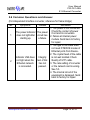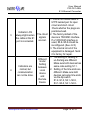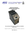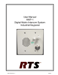
1
PW-FE1-4ETH Interface E1-Ethernet Converter User Manual Providing Better Solutions for Telecommunication Industry http://www.pacificwave-wireless.com User Manual PW-FE1-4Eth E1-Ethernet Converter Content 1. Product description .................................................................. 3 2. Main features .......................................................................... 5 3. Technical specifications............................................................ 6 4. Installation and panel description.............................................. 7 4.1Unpacking ............................................................................... 7 4.2 Front and rear panel of the device ......................................... 7 4.2.1The front panel of the FE1-4ETH .................................. 7 4.2.2 The rear panel of the FE1-4ETH .................................. 9 4.2.3 System test and configuration ................................... 10 5. Applications of FE1-4ETH ....................................................... 11 5.1 Definition of balanced twisted-pair wire sequence ............... 11 5.1.1 100BASE-TX interface wire sequence ........................ 11 5.1.2 E1 interface wire sequence ........................................ 11 5.2 Setting of DIP switch and jumper ......................................... 11 5.2.1 Setting of E1 interface impedance .............................. 11 5.3 Configuration of Ethernet connecting devices ...................... 13 5.4 Simple self-test methods for devices and E1 circuits ........... 13 5.5 Typical applications .............................................................. 13 5.6 Common questions and their maintenance.......................... 15 www.pacificwave-wireless.com Page 2 of 16 User Manual PW-FE1-4Eth E1-Ethernet Converter 1. Product description PW-FE1-4ETH Interface Converter is an Ethernet bridge of high performance, which accomplishes the converting between the 100M Ethernet port and the E1 port. As an extended device of the Ethernet, PW-1E1-4ETH bridge realizes interconnection of four Ethernet by using 1pc E1 channel provided by existing networks with low cost. 100BASE-TX (RJ45) interfaces are provided at the end of Ethernet LAN to accomplish various functions including double Ethernet interface broad band shared, MAC address self-learning, address filtering, address table maintenance and flow control. The device has 4 ETH port, it can work like an intelligent L2 switch. It can be reduce Net node, dispense with device as HUB, consequently reduce the malfunction node. Our PW-FE1-4ETH has the GUI NMS, it can manage the converter like an intelligent L2 switch. It can set the TAG VLAN on these 4 ETH port, can set the special tag like Q-in-Q, can configurable data rate from 32K~100M on each ETH port, can do some QoS setting. E1 interfaces conforming to ITU-T G.703 and G.704 proposals are provided at the end of WAN, supporting RJ45 and BNC connection modes. The E1 ports support both framing and un-framing architecture. The user can select an operating mode for the E1 interface according to the connected E1 environment. This provides flexibility of network application. In the framing mode, the E1 interface provides a rate of N*64Kbps (N=1to31). In Un-Framing Mode,E1 channel provides a rate of 2.048Mbps and accomplishes transparent transmission. www.pacificwave-wireless.com Page 3 of 16 User Manual PW-FE1-4Eth E1-Ethernet Converter If the FE1-4ETH bridge is used in the framing mode, the transmission clock can be either provided internally, i.e. using the main clocking timing mode (INT), or extracted from the E1 channel, i.e. using slave clock timing mode. The FE1-4ETH bridge provides plenty of self-test functions, supporting local loop. It also provides pseudo random code test function to test error codes in the circuit. It is proposed to use the products of this series in pairs. A typical application is shown in figure 1. FE1/ETH ET H POWE R SWITCH/HUB LN K R X E 1 TX LO F LO S TES T A S CR C LOO P PTO K A SD SD SDH H H FE1/ETH ET H POWE R LN K R X E 1 TX LO F LO S TES T A S CR C LOO P PTO K B SWITCH/HUB Figure1 typical application of AN-FE-4ETH bridge www.pacificwave-wireless.com Page 4 of 16 User Manual PW-FE1-4Eth E1-Ethernet Converter 2. Main features In accordance with the provisions of IEEE 802.3, 802.3u Ethernet ITU-T G.703, G.704 and G.823 protocols. E1 interface framing/un-framing optional; balanced 120ohm unbalanced 75ohm optional. The E1 interface uses PCM31 mode, supporting CRC check. E1 interface main/ slave clock optional in the framing mode. In E1 framing mode, number of time slots is optional from 1 to 31. Supporting 2.048Mbps transparent transmission in the E1 un-framing mode. The two 100BASE-TX Ethernet interfaces support 100M half/ full duplex modes. MAC addresses self-learning and addresses filtering functions, reducing the transmission load of the E1 circuit. Built-in 64Mbits SDRAM Ethernet data buffer memory, improving the capability of Ethernet side anti-outburst, assuring high throughput of data transmission. E1 circuit local loop tests. Pseudo random sequence test, facilitating the test of E1 circuit. Perfect circuit test and alarm indication. Optional AC 220V or DC –48V input for bridge of both architectures www.pacificwave-wireless.com Page 5 of 16 User Manual PW-FE1-4Eth E1-Ethernet Converter 3. Technical specifications Protocol: G.703, G.704, G.736, G.823, I.431 IEEE802.3u 100BASE_TX Circuit Interface (E1): Impedance: 75Ω, physical interface: BNC Impedance: 120Ω, physical interface: RJ45 Interface rate :Framing: N*64Kbps,N==0~31; UN-framing: 2.048Mbps Coding: HDB3, Jitter tolerance in accordance with G.823 Output Jitter < 0.05UI Data interface (100BASE_TX): Impedance: 100Ω, interface: RJ45 Interface rate: 100Mbps Coding: Manchester Cable: 75Ω coaxial-cable, UTP5 twisted pair. Transmission range: Data interface: 100m, Circuit interface: BNC: 600m; RJ45: 300m Indicator: indicating power, connection states of data and circuit interfaces, operation state, test state and trouble alarm. Dimensions (LxWxD): 210 x 40 x 140mm Power Supply : 85V ~ 264 Volt AC input , 5Volt/1Amp Output -36V ~ -72 Volt DC Input, 5Volt/1Amp Output Power dissipation: 3Watt Operation Temperature : 00C ~ 500C Storage Temperature : -200C ~ 800C Humidity :5% ~ 90% (no Condensation) www.pacificwave-wireless.com Page 6 of 16 User Manual PW-FE1-4Eth E1-Ethernet Converter 4. Installation and panel description 4.1. Unpacking Check the accessories and spare parts when opens the package. ■ FE1-4ETH Bridge ■ Operation manual ■ A supply cord (only for AC type) ■ Two type of connector/plugs : BNC or RJ45 In case of missing or any damage during transportation, immediately contact our offices or agencies. 4.2 Front and rear panel of the device 4.2.1. The front panel of the FE1-4ETH bridge The front panel of the FE1-4ETH Bridge is shown as below Figure 2 front panel of FE1-4ETH Bridge Explanations for the two rows of indicators at the left are as follows: POWER: Power. Always lights after starting up. LK/AT1:Flickers if ETH1 is connected and transmitting data. LK/AT2:Flickers if ETH2 is connected and transmitting data. LK/AT3: Flickers if ETH3 is connected and transmitting data LK/AT4: Flickers if ETH4 is connected and transmitting data www.pacificwave-wireless.com Page 7 of 16 User Manual PW-FE1-4Eth E1-Ethernet Converter LOF: Alarm indicator lamp for input signal out-of-frame in E1 line. Constantly lightening indicates the alarm with local device; flash indicates the alarm with opposite device. Alarm status of opposite device can be detected only at framing mode. LOS: E1 link interruption alarm. Always lights after starting up till synchronization is established. It also lights in case of E1 link interruption or signal loss in communication. AIS: Always lights after receiving a alarm indication signal. LOOP: Always lights in testing if transmitting local loop, flickers if remote E1 interface loop instructions or pseudo-random sequence test instructions. RAL : Always light when E1 line of remote site cut down www.pacificwave-wireless.com Page 8 of 16 User Manual PW-FE1-4Eth E1-Ethernet Converter 4.2.2. The rear panel of the FE1-4ETH bridge The AC input rear panel of FE1-4ETH Bridge is shown in figure 3. Figure 3 AC input rear panel of FE1-4ETH Bridge 220V AC: AC socket with two cores OF ON: Power Switch for Electrical Power 8 Bits coded Switch: System configure, more description in 4.2.3 E1-75Ω: BNC Tx/Rx socket for 75ohm impedance E1 interface E1-120Ω: RJ45 socket for 120Ω impedance E1 interface ETH: RJ45 socket for 100Mbps Ethernet interface The DC input rear panel of FE1-4ETH Bridge is shown in figure 4. Figure 4 DC input rear panel of FE1-4ETH bridge 48VDC : DC-48Volt Power Supply Connector The others are the same as in figure 3. www.pacificwave-wireless.com Page 9 of 16 User Manual PW-FE1-4Eth E1-Ethernet Converter 4.2.3 System test and configuration S5 We can find 8pcs DIP Switch (From Left to Right : 1st to 8th Swich) with below detail description : S5.1, 1st Switch-Main/Slave Clock setting (valid only in Framing mode). ON for Main clock (INT-CLK) and OFF for slave clock (LINE-CLK). S5.2, 2nd Switch- BC_EN to set Bandwidth Coupling, ON to follow bandwidth setting (time slot) of remote converter. OFF to use bandwidth setting (time slot) of local converter S5.3, 3rd Switch-LLOOP Local Loopback Setting (For Testing Purpose) ON for E1 interface in direct Loop back mode. OFF for E1 Interface not in direct Loop back mode.. S5.4, 4th Switch- 7221_SEL to Set Version of Remote Corverter ON for working with the old Firmware Version Device. OFF for working with same Firmware Version of Device S5.5, 5th Switch – NULL (Not in Used) S5.6 to S5.8, 6th to 8th Switch - To select between 75Ω or 120Ω When S5.6~S5.8 is set 75Ω, The E1 circuit uses BNC Coaxial cable When S5.6~S5.8 is set 120Ω, The E1 circuit uses RJ45 sockets and 120Ω balanced twisted-pair. www.pacificwave-wireless.com Page 10 of 16 User Manual PW-FE1-4Eth E1-Ethernet Converter 5. Applications of FE1-4ETH Bridge 5.1 Definition of balanced twisted-pair wire sequence 5.1.1 100BASE-TX interface wire sequence The RJ45 Unshielded twisted-pair for FE1-4ETH interface can use DCE or DTE standard stipulations, it support AUTO MDI/MDX function. 5.1.2 E1 interface wire sequence 1 & 2 are transmitting lines, 4 & 5 are receiving lines, as shown below: 1. TX+ Positive end of data transmission 2. TX- Negative end of data transmission 1 2 3 4 5 6 7 8 3. Idel 4. RX+ Positive end of data reception 5. RX- Negative end of data reception 6. Idel 7. Idel 8. Idel Figure 5 RJ45 balanced twisted-pair wire sequence for E1 interface 5.2 Setting of DIP switch and jumper 5.2.1 Setting of E1 interface impedance Below are switch which allow user to set number of Time Slots according to the expected rate : as shown by Figure 6 : E1-TS 0 1 7 8 ON ON 1 2 3 4 5 6 7 S1 8 15 16 ON ON ON 1 2 3 4 5 6 7 8 1 2 3 4 5 6 7 S2 www.pacificwave-wireless.com S3 23 24 31 ON ON 8 ON 1 2 3 4 5 6 7 8 S4 Page 11 of 16 User Manual PW-FE1-4Eth E1-Ethernet Converter SWITCH SW 0 (S1.1) SW 16 (S3.1) (Valid If SW0 is off) Status ON OFF ON OFF Function Unframed 2048KBps Framed in Xx64K CCS (PCM31) CAS (PCM30) Description Full E1 used (31Time Slot) User can set X-Time Slot to use Max 31 Timeslot Max 30Timeslot ● 1st switch-SW0 (S1.1) is used to set E1 framing/non-framing. ―ON‖ refers to non-framing mode (2.048Mbps), despite of whatever positions are set at other switches (S2,S3,S4). ● 2nd to 32nd Switch (S1.2~S1.8, S2.1~S2.8, S3.1~S3.8, S4.1~S4.8) SW1—SW31are respectively used to set 1st–31st time slots (this only function if S1.1 is off). Set at ―ON‖, the corresponding time slot is selected; Set at ―OFF‖, the corresponding time slot is not selected. The rate of E1 interface dependent on Number of Selected time slots. For example: if 3rd switch (S1.3) is ―ON‖ and other switches is ―OFF‖ indicates that 2nd Time slot is selected, at this setting E1 rate is 64K; If 7th(S1.7) & 10th(S2.2) switches is ―ON‖ and other switches is ―OFF‖ indicates that 6th& 9th Time slots are selected, E1 rate is 2*64K=128K. SW-16 (S3.1) is used to set E1 frame structure to be PCM30(CAS mode) or PCM31 (CSS mode) ‗0FF‘—PCM30, 16th time slot not being used for transmission service; ‗ON‘—PCM31, 16th time slot can be used for transmission service. www.pacificwave-wireless.com Page 12 of 16 User Manual PW-FE1-4Eth E1-Ethernet Converter 5.3 Configuration of Ethernet connecting devices The equipment uses 100BASE-TX Ethernet interfaces and supports adaptive 100M half/full duplex mode. Ethernet devices connected to FE1-4ETH bridge (such as SWITCH, HUB, Ethernet adapter card (NIC), etc.) can be set to 100M full duplex, 100M half duplex, adaptive 100M half/full duplex and adaptive 10/100M. 5.4 Simple self-test methods for devices and E1 circuits Test 1: test of back-to-back connection Connect two FE1-4ETH bridge devices back to back, ping the other‘s IP address on the two computers to test the two devices. PC1 PC2 A B FE1/ETH FE1/ETH ET H POWE R LN K R X E 1 T X LO F LO S ET H TES T A S CR C LOO P PTO K POWE R LN K R X E 1 T X LO F LO S TES T A S CR C LOO P PTO K Test 2: test of E1 circuit transmission error codes. Connect the device in the real operational environment, check the E1 circuit with the loop and pseudo-random sequence test function provided by the device. 5.5 Typical applications Mode 1: connect Ethernet with E1 networks. SDH, PDH and DDN networks have already been widely adopted. With E1 channels provide by such networks, bridging connection and interconnection of two Ethernet networks at different locations can be easily realized by FE1-4ETH bridge. www.pacificwave-wireless.com Page 13 of 16 User Manual PW-FE1-4Eth E1-Ethernet Converter FE1/ETH ET H POWE R LN K R X E 1 TX LO F LO S SD SD SDH HH TES T A S CR C LOO P PTO K A SWITCH/HUB FE1/ETH ET H POWE R LN K R X E 1 LO F TX B LO S TES T A S CR C LOO P PTO K SWITCH/HUB Connecting two Ethernet networks with an E1 network. Mode 2: Extend an Ethernet network with existing twisted pair or coaxial cable. Connected with twisted pair or 75Ω coaxial cable, the E1 ports of FE1-4ETH Bridge support a transmission range of 300m or 600m. Two Ethernet networks at different locations can be bridged by two FE1-4ETH bridge with existing twisted pair or coaxial cable. FE1/eth FE1/eth ET H POWE R SWITCH/HUB LN K R X E 1 T X LO F LO S ET H TES T A S CR C LOO P PTO K A POWE R LN K R X E 1 T X LO F LO S B TES T A S CR C LOO P PTO K SWITCH/HUB Extending Ethernet with existing twisted pair and coaxial cable www.pacificwave-wireless.com Page 14 of 16 User Manual PW-FE1-4Eth E1-Ethernet Converter 5.6 Common Questions and Answer. (For independent interface converter, reference for frame bridge) No. Symptoms Causes Remedies 1. The power is not connected. Check the contact of power The power indicator The power Cord and its converters. 1 does not light after circuit has 2. Failure at internal power starting up. a failure. module. Send back to factory for repair. 1. The type of the cable does not meet DTE/DCE modes of Ethernet ports from Device.. 2. The crystal head of the cable Indicator LNK does Integrity is not well molded. Check not light when the test of link Quality of UTP cable. 2 Ethernet network has not 3. The rate setting of converter is connected. passed. or the network card is wrong. See 5.3. 4. The internal circuit of the equipment is damaged. Send back to factory for repair. www.pacificwave-wireless.com Page 15 of 16 User Manual PW-FE1-4Eth E1-Ethernet Converter 3 4 Indicator LOS always lights when the cable at the E1 port is connected. Indicators are normal, but communication can not be done. 1. Check the coaxial cable or UTP5 twisted pair for open circuit and short circuit. Check whether the plugs are positioned well. The circuit 2. The factory default of the signals device is 75Ω BNC interface. are lost. If a 120Ω RJ45 interface is used, S5.6~S5.8 should be reconfigured. (See 4.2.3) 3. The internal circuit of the equipment is damaged. Send it to factory for repair. 1. The setting of framing or Different un-framing are different. mode/ Make sure both devices has Setting same code setting S1.1. between 2. Setting of the time slots are Local different. Make sure both device devices set same time slots and via the dip switch Remote S1.2~S1.8, S2.1~S2.8, Device S3.1~S3.8, S4.1~S4.8.. www.pacificwave-wireless.com Page 16 of 16