1
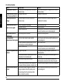
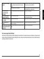
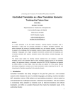
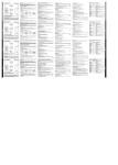
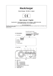
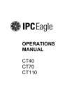
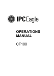
English Copyright " 2008 by CTE International Italy. All rights reserved. 1 Introduction 2 2 Safety warnings 2.1 Symbols used 2.2 Warnings 2.3 Technical support 3 3 3 4 3 Controls and features 3.1 Description 3.2 Displayed symbols 4 4 6 4 Setup 4.1 Items supplied with the radio 4.2 Fixing/removing the optional belt clip 4.3 Removing/installing the battery pack 4.4 Recharging the battery pack 7 7 7 7 8 5 Basic features 5.1 Switching the radio on and off 5.2 Backlighting 5.3 Checking the level of the batteries charge 5.4 Adjusting squelch (suppressing background noise) 5.5 Selecting the operating channel 5.6 Receiving and transmitting 5.7 Busy channel lockout 5.8 Operating modes (open and restricted traffic mode) 5.9 Programming the CTCSS/DCS codes 5.10 Monitoring function 9 9 9 9 9 9 10 11 11 12 12 5.11 Selecting the transmission power 5.12 Emergency mode 5.13 Scan function 13 13 13 6 Functions of the MENU key 6.1 Mode VOX (e-VOX) 6.2 Roger bip 6.3 Keyboard tones 6.4 Selecting the call tone 6.5 Scrambler 6.6 Out of range indicator 6.7 Cloning (copying data between radios) 14 14 14 15 15 15 15 15 7 Connecting the audio accessories 16 8 Care and maintenance 8.1 Cleaning the radio 8.2 Battery recharge contacts 8.3 Connectors 8.4 Battery-charger 8.5 Troubleshooting 8.6 Correcting logic faults (Soft Reset) 17 17 17 17 17 17 19 9 Technical specifications 20 10 Tables of codes 10.1 Correspondence of the HP450 2A reference number -Frequencies of CTCSS tones 10.2 Correspondence of the HP450 2A reference number - DCS codes 21 21 21 1 English Table of contents English 1 Introduction Thank you for choosing one of our products. Besides being characterised by a compact design, a housing in aluminum die-cast and a high resistance to all types of aggressions, Alan HP450 2A rugged is an industrial and portable dual band device (PMR and PMR446) device particularly suited for very noisy environments and able to guarantee maximum robustness. The unit is pre-set at factory in the PMR446 band. To enable the PMR band, simply ask your dealer to programme (with a power up to 5W) your device. We remind you that the PMR band is subject to individual licence required to the Ministry (see the “Restrictions on the use” chart). Alan HP450 2A can be used in the hardest working conditions because it is compliant with the severe requirements of standards MIL 810 c, d, e, f, and has an IP67 class, which means that it is waterproof down to a maximum depth of 1 meter of water. The device offers also truly innovative features like the scrambler for confidential communications and e-VOX that be used also without external microphones, unlike traditional handsfree systems. Alan HP450 2A is supplied in the spacious semirigid EVA box that is large enough to hold the wide range of accessories supplied with the device: battery, holster in rigid polycarbonate with swiveling clip (360°), belt clip and a two-position fast charger. • 312 channels - These channels can be used to store several combinations of radio/tone frequencies. HP450 2A can operate in open or restricted traffic. It is supplied with 312 channels; 99 are pre-set at factory: - 8 are referred to open traffic 2 - 91 operate on the restricted traffic - the remaining 213 are not programmed • Class IP67 for maximum robustness and reliability - The housing safely protects the device from dust and from water infiltration up to a maximum depth of one meter for 30 minutes • MIL STD 810 c, d, e, f - The compliance with these severe US military standards is itself a guarantee of maximum reliability • Large display - 11 icons and 2+2 digits • Out of range function - Warns the user when the device is out of range • E-VOX - Enables to communicate handsfree without audio accessories or having to press buttons • 1W audio power, suitable for noisy environments • Hi/Lo power (active in the PMR band) • In compliance with ETS 300 296-2 and ETS 300 086-2 • Built-in inversion scrambler - Protects communications 2Depending on the version, HP450 2A may be fitted with a 2,200 mAh lithium battery or a 1,100 mAh Ni-MH battery. • The version with high capacity lithium battery has an autonomy of 26 hours 2The actual features available depend on the programmed settings. For more information, contact an authorised distributor or the radio link provider. IThe resistance to immersion is guaranteed only if the battery and protective cover of the connectors have been correctly installed. In the event of accidental contact with water, the device must be immediately dried. 2The manufacturer may change these features without warning as a result of improvements applied to the products. 2 Safety information Do not handle the transceiver by its aerial. The use of a faulty aerial could seriously damage the transmission power stages. 2.1 Symbols used 2Practical recommendations that help to improve performance. 2.2 Warnings Carefully read all the instructions contained in the manual and on the labels applied to the device. The manufacturer has taken all possible measures to ensure that all the information contained in this manual is complete, accurate and current. However, CTE International shall not be responsible for damages for which it is not directly responsible. Modifications performed by unauthorized personnel may affect the validity of the information contained in this manual. • This transceiver is compliant with Directive 99/05/EC. Before using the device, always refer to the restrictions on the use enclosed to this manual. • Always use the professional transceiver selected in compliance with the regulations in force in the country of residence and refrain from using it when its use is forbidden or if it is likely to cause interference or serious hazards. Attention The portable HP450 2A extrá transceiver has been specifically designed to guarantee a long-term safe and reliable operation. For optimum and safe performance, always observe the basic precautions applicable to all electric equipment: Do not keep the aerial of the radio too close to your body during transmission. Users with cardiac stimulators, acoustic implants or medical devices should always consult their doctor or the manufacturer of these devices to make sure that they are adequately protected against RF energy. Do not use the radio close to unshielded primers in explosive atmospheres. -20°C/+55°C The radio is designed to be used in extreme conditions. However, it is always advisable to avoid exposing it to very high or low temperatures (temperatures below –20°C or above +55°C). Do not expose the transceiver to excessive vibrations, dust or rain. Do not attempt to disassemble or repair the radio or battery (except for performing the routine maintenance operations described in this manual). 3 English IWarnings Use original accessories only in order not to damage the radio. English Do not use the radio next to water sources and not spill liquids on the radio. If the transceiver gets wet, dry it immediately with a soft and clean cloth. 3 Controls and functions 3.1 Description 1 2 3 12 Always remove the battery and switch the radio off before cleaning it. Verify that the supply source is compatible with the battery-charger supplied (AC adapter). Do not place any objects on the power cable of the battery-charger in order not to damage it. 4 11 5 10 6 9 7 13 14 15 8 2.3 Technical support Write the serial number of your transceiver in this space. This number is printed on the nameplate inside the battery compartment of the transceiver and must be provided for technical support and/or in the event of loss and/or theft of the unit. HP450 2A transceiver - Serial Number_______________________ 4 3.1.a Front and left sides 1 Aerial 2 On/volume knob 3 Status LED – Red when the HP450 2A radio is in transmission mode, green when it is in reception mode 12 13 14 15 LCD display – (O 3.2) p key q key Built-in microphone Built-in speaker MENU Key (O 6) SCAN/LOCK key – (O 5.13) HI/LO key– Enables to select a high or low transmission power (not active in the PMR446 band - O 5.11) E (emergency) key – Enables to call the preset emergency channel (not active in the PMR446 band - O 5.12) PTT (Push To Talk) key – Hold this button down to set the transceiver in transmission mode MON key – Hold this key down to enable the monitoring function (O 5.10); press it twice quickly to adjust the squelch CALL key – Press it briefly to start the preset audio call (tone) 3.1.b Rear and right sides 16 Battery pack – Powers the portable transceiver. 17 Battery pack lock – Enables to remove the battery pack from the radio (O 4.3.a). 18 Clip fixing grooves – Enable to fix the optional clip directly onto the battery pack and hang the radio to your belt without holster. 19 Battery recharge contacts – Enable to connect the batterycharger to the desktop quick charger (O 4.4). 20 Fixing screw - Fixes in place the protective cover of the microphone connectors. 21 Protective cover of the microphone connectors. 22 23 SPK connector (under the cover) - 3.5 mm jack connector for external speaker. Together with the MIC connector it can be used to connect optional microphones. MIC connector (under the cover) - 2.5 mm jack connector for external microphone. Together with the SPK connector, it can be used to connect optional microphones. This connector can also be used for the Cloning feature (O 6.7), which requires however the connection of the special optional cable. 17 18 20 16 21 22 23 19 5 English 4 5 6 7 8 9 10 11 3.2 Displayed symbols The transceiver has an LCD display that continuously displays information on the operating status of the radio. English Symbol Meaning Description Battery charge Indicates the charge level of the battery. Strength of the received and transmitted signals Low TX power According to the number of bars displayed: • Reception mode - Indicates the level of the received signals • Transmission mode- Indicates the level of the output power. In standby these large digits indicate the currently selected radio channel. During the programming of features, they are used to display different parameters or values (for example bP = Beep that confirms that a key has been pressed). During programming, it is used to display different values and parameters. For example on stands for ON (enabled feature) and oF stands for OFF (disabled feature). Indicates that a low transmission power has been selected. Keyboard lock Indicates that the keyboard has been locked. CTC CTCSS Indicates that the currently used channel has been programmed with a CTCSS tone. DCS DCS Indicates that the currently used channel has been programmed with a DCS code. Channel scan Indicates that the scan (automatic signal scan) is in progress on the preset channels. Priority channel Radio/multifunctional channel Multifunctional indicator LO SCAN P DW VOX 6 Dual Watch Indicates that the currently selected channel has been programmed as a priority channel during the scan. Indicates that the Dual Watch (fast search of signals on two channels) is in progress. Roger bip Indicates that the Roger bip function has been enabled. e-VOX Indicates that the e-vox (enhanced Voice Operated eXchange – handsfree transmission) has been enabled. pack, then slide the clip downwards until it snaps in place. 4.1 Items supplied with the radio 4.3 Removing/installing the battery pack Before using the transceiver, always make sure that the semi-rigid EVA box contains the following items: • The transceiver with the rubber (fixed) aerial and the rechargeable battery pack • The holster in rigid polycarbonate with rotating clip to fix the radio to the belt. To properly fix the radio into the holster, push the holster. • The desktop battery-charger (that includes the charging seat, the AC adapter and AC cable) • Belt clip • Rubber cap for the Mike/SPK jacks • The operating manual (this manual) If any of the above-described parts are missing or damaged, immediately contact the retailer. 2To operate the radio, use the Ni-MH or Li-Ion battery pack. To remove the clip from the battery pack, unhook the battery pack from the radio, then pull the release lever, situated on the upper part of the clip, outwards, then remove it pulling it upwards. To reinsert the clip, insert the guides into the grooves on the rear of the battery 4.3.a Removing/installing battery pack To insert the battery pack: 1) Insert the battery pack as shown in the figure. 2) Push the battery pack down towards the transceiver until it clicks in place. 1 Lever 4.2 Fixing/removing the optional belt clip Depending on the model, the transceiver can be fitted with the following battery packs: • BP4511 - NiMH battery pack, 1,100 mAh • BP4522 - Li-Ion battery pack, 2,200 mAh IIf you are planning not to use the transceiver for a long period of time, remove the battery pack. IBe careful not to soil/damage the contacts of the battery compartment of the radio and battery pack. Guide 2 Groove To remove the battery pack: 1) Press and hold down the battery release button. 2) Remove the battery pack from the upper side of the transceiver. 7 English 4 Setup English 4.4 Recharging the battery pack The fast double desktop battery-charger enables to recharge the battery pack without removing it from the radio or to recharge the battery pack separately. The charger is able to recharge both Li-Ion and Ni-MH battery pack. 2At the end of the recharge operation, it is possible to leave the radio/battery pack in the charger, because the latter has a special protection that prevents the battery pack from being damaged by overvoltages. 2Battery packs tend to loose their charge if they are not used (automatic discharge). This condition is perfectly normal. All models of battery packs tend to loose 10 - 20% of their power after a few days. IIf the battery pack is new, it is necessary to fully recharge it before using it. Then, it is sufficient to follow the recommendations given in paragraph 4.4.a. IAlways use the battery-charger with the above-described models of battery packs. Do not attempt to use the batterycharger to recharge other types of batteries (and specifically alkaline batteries), as this operation could cause explosions and personal injuries. IAlways keep the battery-charger compartments clean. 4.4.a Recharging the radio with battery pack New batteries are not charged. The battery provides maximum efficiency after 3-4 full charge/ recharge cycles. 1) Connect the connector of the transformer to that of the base. 8 2) Connect the plug of the power cable of the adapter to a grounded AC power socket. 3) Verify that the radio has been switched off. 4) Insert the radio into the compartment of the batterycharger, with the keyboard facing upwards. The recharge starts and the orange indicator UNIT lights. 5) Once the recharge is completed (see following table), UNIT turns to green. ‹ ‹ Indicative time required to fully recharge the battery Type of battery pack Recharge time (hours) BP4511 (NiMH, 1,100 mAh) about 1 hour BP4522 (Li-Ion, 2,200 mAh) about 2 hours 4.4.b External battery pack Insert the battery pack into the compartment on the rear of the battery-charger. BATT turns red. Once the recharge has completed, BATT turns green. 5.1 Switching the device on and off Turn the On/Volume knob clockwise until it clicks: the LCD displays switches on and the device issues a confirmation beep. 2The backlighting of the LCD display switches off automatically after five seconds for energy saving purposes, while the display remains on. To switch the transceiver off, turn the On/Volume counterclockwise. 5.2 Backlighting When you switch the device on or press one of the HI/LO, SCAN/ LOCK, MENU or MON keys, the device automatically enables the backlighting for approximately five seconds to allow you to read the displayed messages if the lighting is not adequate. To keep the backlighting on for 5 seconds more, press another key. 2The backlighting of the display consumes battery energy and should therefore be used sparingly. 5.3 Checking the level of the batteries charge 5.4 Adjusting the squelch (suppressing background noise) The radio is fitted with a device called squelch that attenuates the background noise when no signals are present. The enabling threshold can be adjusted according to your specific needs. 1) Briefly press MON twice. Sq displays, while the right section displays a number from 1 to 8, depending on the squelch level you have set. 2) Press q several times to set the enabling threshold on 1 (minimum value). You will hear a slight background noise. 3) If the radio is not receving signals, press p several times to gradually increase the squelch value and stop as soon as you detect the minimum value that guarantees a stable noise suppression. 4) Press PTT (or wait five seconds). The device returns to the standby mode and stores the settings you have selected. 2Make sure you do not set an excessively high squelch level because in this case you may not be able to receive weaker signals. On the other hand an excessively low squelch value could enable the squelch even when no signals are present. 2This adjustment must be carried out within five seconds, otherwise the device returns to standby mode and stores the currently set value. When the transceiver is in standby mode, the battery charge indicator continuously displays the residual charge of the battery. indicates that the charge is insufficient and that the 2Icon device will soon switch off. I Squelch must always be adjusted when no signals are present. 2The consumption of the battery charge is affected by the volume level set. 1) Press MENU once. The display flashes. 2) Press p or q to select the desired channel. To quickly scroll the 5.5 Selecting the operating channel 9 English 5 Basic features English channels hold down p or q. 3) Press PTT (or wait five seconds) to store the setting. 2It is obvious that other parties shall also have to select the same channel, otherwise communications will not be possible. 2For more information on CTCSS tones and DCS codes, see O 5.8 and 5.9. 2This adjustment must be carried out within five seconds, otherwise the radio returns to the standby mode storing the currently set channel. 2The reception/transmission mode described below is the so-called "open traffic mode", which is simplest one. It is however possible also to set other modes as described in paragraph 5.8. During reception and transmission try and keep the aerial as vertical as possible so that the signal can be transmitted without hindrances. This precaution optimises the radio signal. 5.5.a How to select the channel The HP450 2A radio has been programmed as follows: • Channels from 1 to 8 are programmed with the 8 radio frequencies of the PMR446 band • Channels from 9 onwards are programmed with the same repeated radio frequencies (for example channel 9 has the same frequency of channel 1, channel 10 has the same frequency of channel 2, etc.), but also include CTCSS tones or DCS codes. If you select these channels, CTC or DCS displays. 2For the PMR band, your dealer will inform you about the channels to use I If you need to communicate with transceivers of different brands, it is generally preferable to use one of the first eight channels to ensure maximum compatibility. It is obviously necessary to select the less used channel of your area. If the parties you are communicating with use a HP450 2A device (or a device with CTCSS tones), you may choose any channel. If all the eight PMR446 frequencies are occupied in your area, you can select a channel from 9 to 16 (the less busy one) to allow the CTCSS tone or DCS code to enable you to listen to communications of the members of your group only. 10 5.6 Receiving and transmitting 5.6.a Reception As soon as the signal has been received, the squelch disables automatically, the status LED turns green and icon displays showing the intensity of the received signal. 2If the signal is received fragmented because of weak signals, try using the monitoring feature. 5.6.b Transmission 1) Verify that other parties are not connected to the selected channel (status LED off). 2) Hold PTT down: the status LED turns permanently red to indicate that the transmission is in progress, while indicator indicates the transmission power. 3) Wait a few seconds, then talk normally at about five centimetres from the transceiver transmitter. Your message will be simultaneously heard by all the parties listening to the same channel. 4) To end the communication, press PTT: the status LED switches off to indicate that the device has returned to the reception mode 5.7 Busy channel lockout The BCLO and TOT functions are disabled by default. If BCLO has been enabled and the channel is busy, the selection of PTT or CALL will have no effect and the radio will issue an error beep. As soon as the channel is free, PTT and CALL shall automatically resume ordinary operation. 5.7.a Transmission timer (TOT) The HP450 2A radio can be programmed with a transmission timer that temporarily blocks transmission if the radio has been used beyond the maximum time permitted. The radio is forced in reception mode if it continues transmitting after the preset timer threshold has been reached. To restart the transmission, it is sufficient to release and then press again the PTT. 5.8 Operating modes (open or restricted traffic) HP450 2A can be used in two modes: Mode name: Open traffic (without CTCSS/ DCS) Default setting From channel 1 to 8 Restricted traffic From channel 9 onwards (with (with CTCSS/ several CTCSS DCS) tones or DCS codes) Comments Guarantees maximum compatibility with the devices of other manufacturers. However, if the channel you are using is used also by other parties, you will also receive their communications. CTCSS and DCS tones are similar to access codes and enable the radio to communicate only with the parties that use the same frequency or have set the same code. 2For information on how to change the CTCSS tone or DCS code of a channel programmed in restricted traffic mode, see O 5.9. 2The restricted traffic mode enables several radios to use the same radio frequency. However, if several parties (for example a user of group A and a user of group B) simultaneously use the same channel for transmission purposes, interference may occur. For this reason, it is advisable not to transmit if the radio signals that the channel is busy although there are no communications. 2The restricted traffic mode does not guarantee the privacy of communications. In this mode it in fact possible to listen also to parties that use CTCSS tones/DCS codes, although it is not possible to call them because they would not be able to receive the 11 English and icon disappears. 2Only one user at a time can talk during radio communications. Therefore, it is important not to transmit when you are receiving a communication and use the transmission mode sparingly to allow other users to use the feature. 2Transmission consumes a significant amount of energy and should therefore be used sparingly to prolong the battery life. Alternatively, it is also possible to select a low transmission power. 2 If you are unable to contact a station that you have no problems in receiving, the station may be using CTCSS tones or DCS codes (O 5.8). English call. To communicate in confidential mode, enable the scrambler O 6.5. 2If you need to use the HP450 2A radio next to electric equipment that generates impulses that frequently enable the squelch of the radio (that is the radio cannot be permanently silenced when there are signals and noise can be occasionally perceived), it is generally preferable to use the restricted traffic mode. 5.9 Programming the CTCSS/DCS codes It is possible to change the CTCSS tones or DCS codes on all the channels. You can set different codes in TX and RX. 5.9.a Selecting the CTCSS tones 1) Select the operating channel. 2) Press MENU twice. CTC displays on the left along with the flashing value that has been set on the right: oF (disabled) or a number ranging from 1 to 38 (CTCSS tone), depending on the channel in use. 3) Press p or q to select the CTCSS tone in RX. 4) Press PTT to store the tone (or wait five seconds). 5) Press MENU three times. The led blinks red. 6) Press p or q to select the desired CTCSS tone in TX. Push PTT to store the tone (or wait 5 seconds) 5.9.b Selecting the DCS codes 1) Select the operating channel. 2) Press MENU three times. DCS displays on the left along with the flashing value that has been set on the right: oF (disabled) or a 12 number ranging from 1 to 83, depending on the DCS code used. 3) Press p or q to select the DCS setting in RX. 4) Press PTT or wait five seconds to store the DCS code. 5) Push MENU three times. The led blinks red. 6) Push p/qto select the DCS code in TX.Push PTT to store the DCS code in TX. 5.9.c LED operation with CTCSS/DCS When you use the restricted traffic mode, the status LED provides slightly different indications as compared to those of the open traffic mode: • Off: indicates that no signal is being received (as in the open traffic mode) • Green: indicates that a signal with a correct CTCSS/DCS tone is being received (it is enabled together with the radio volume) • Orange: indicates the receipt of a signal without a CTCSS/DCS tone or with a different CTCSS/DCS tone (the volume will not be enabled) • Red: indicates that the transmission is in progress (as in the open traffic mode) 5.10 Monitoring function - Monitor/squelch This feature can be used to monitor the selected channel before transmitting and receiving low intensity signals. Press MON to disable the mode (CTCSS). To disable the squelch (noise reduction), hold MON down for approximately 3 seconds. In this mode, you can hear all the noise present in the environment. 2The disabling of the squelch increases the consumption of the battery power. The HI/LO button is disabled in the PMR446 band. In the PMR version, you can select the high or low power (1/5W). at the top left The transmission power is displayed with the icon of the screen. To start the scan briefly press SCAN/LOCK. SCAN displays. During the scan you can also: • Reply to a call by pressing PTT. To disable the scan, press once more SCAN/LOCK. SCAN disappears from the display and the transceiver returns to the standby mode on the channel that had been selected before starting the scan. 5.12 Emergency mode 2If a priority channel has been programmed and you select it, P displays in the lower left section of the screen. The E button is disabled in the PMR446 band. In Emergency mode, the only channel displayed is the emergency one; the power output is high level. 5.13 Scan function 5.13.a Locking the keyboard Hold down SCAN/LOCK for approximately three seconds to highlight symbol (in the lower left section of the screen). All the functions of the radio are temporarily disabled, except transmission (PTT), calls (CALL) and the features for the adjustment of the squelch/monitor. To release the keyboard, repeat the operation described. Symbol disappears from the display. 2If the radio is in Scan or Dual Watch mode and you press SCAN/ LOCK, these features are disabled without the keyboard being locked. To perform the latter operation, it is therefore necessary to press the key once more. I The channels to scan must be previously enabled through the programming software or by an authorised dealer. 5.13.c Dual Watch (dual listening mode) This function enables you to scan two selected channels only. 1) Select the desired operating channel. 2) Press MENU. DW (Dual Watch) flashes on the display along with oF (Dual Watch disabled). 3) Press p or q to select the second channel. 4) Press PTT (or wait five seconds) to enable the Dual Watch feature. DW displays in Dual Watch mode. To disable the Dual Watch feature, briefly press SCAN/LOCK. 5.13.b Channel scanning This function is useful to keep a check on the channels previously programmed by the programming software or by on authorised dealer. 13 English 5.11 Selecting the transmission power English 6 Functions of MENU key 1) Press MENU several times to highlight the desired function. 2) Press p or q to set the selectable value for the displayed feature. The following table lists the features that can be set (the number of times key MENU has to be pressed is indicated in the columns on the left): MENU 1 2 3 4 5 6 7 8 9 10 11 Feature Selection of the operating channel Selection of the CTCSS tones Selection of the DCS codes Mode Dual Watch Roger bip Keyboard tones Selection of the call tone Scrambler Out of range indicator Cloning (copying data between radios) 6.1 E-VOX Display (channel) CTC DCS VOX DW bP CA SC oU CL Disabled NO NO NO YES YES NO NO NO NO YES NO e-VOX (enhanced Voice Operated eXchange) enables to start a transmission without pressing any keys, but by simply talking. The sensitivity of e-VOX can be adjusted according to needs; for example depending on whether you use the transceiver only or the optional microphone or on whether you use the radio in a very noisy or noise14 less environment. 1) Press MENU several times until VOX flashes on the display (normally 4 times). The right section of the displays shows the current VOX setting (for example oF if the feature is disabled). 2) Press p or q to highlight the number related to the desired setting as shown in the following table: No. Sensitivity Comments oF VOX disabled. transmission can be started only by pressing PTT 1 Minimum In this case you can talk even in a very low voice and at a greater distance from the radio. However, if the environment is too noisy, transmission may be accidentally started by any noise. 2 Medium Intermediate setting 3 Maximum In this case you will have to talk in a loud voice and close to the radio, but it is also possible to use the radio in very noisy environments. 3) Press PTT to confirm. 6.2 Roger bip “Roger bip” is a short audio tone that the radio issues when you release PTT at the end of the transmission. To enable/disable roger bip: 1) Press MENU six times to highlight . 2) Press p or q to enable or disable it. 3) Press PTT to confirm. 2If the Roger bip feature has been enabled and the radio is in standby mode, displays. 1) Press MENU to highlight bP (bip). 2) Press p or q to enable or disable the keyboard tones. 3) Press PTT to confirm. 2When you press one of the keys to disable the keyboard tones (oF) in step 2, the radio will not issue a beep to confirm the disabling. The re-enabling of the tones (on) is instead signaled with a beep. 6.4 Selecting the call tone Briefly press CALL to start an audio call. To select one of the five available tones: 1) Press MENU eight times. CA (CALL) displays on the left along with the currently set value: oF (disabled) or 1, 2, 3, 4 or 5, according to the tone in use. 2) Press p or q to select the desired setting. You can listen to the tone you are setting through the speaker. 3) Press PTT to exit. 2If you select oF (Disabled), the call function shall be disabled. Thus, the selection of CALL shall produce no effect. 6.5 Scrambler The scrambler is designed to protect communications. This feature prevents parties from other networks from hearing and understanding voice communications. To enable/disable the scrambler: 1) Press MENU nine times. SC (Scrambler) 2) Press p or q to enable/disable the scrambler. 3) Press PTT. If the scrambler is enabled, the status LED flashes in green (two repeated flashes in green). 2When the scrambler is enabled, it is not possible to clearly receive communications. Therefore, before enabling it, it is necessary to make sure that all the radios you wish to communicate with have enabled this feature, otherwise you will not be able to communicate with them. 2The scrambler of the transceiver does not fully guarantee the safety of communications. 6.6 Out of range indicator If this feature is enabled, the HP450 2A will issue a double beep when the radio is out of range. I The radio with which you are communicating must also enable this feature. To enable/disable the out of range indicator: 1) Ask the other radio to enable the feature. 2) Press MENU till oU (Out of range) is displayed. 3) Press p or q to enable or disable this feature. 4) Press PTT (or wait five seconds). 6.7 Cloning (copying data between radios) The Cloning feature enables to copy all the settings (for example channels, CTCSS/DCS, call tones, enabled/disabled features) onto one or more HP450 2A radios. 15 English 6.3 Keyboard tones English 6.7.a Connection 1) Connect the two ends of the programming cable to the MIC connectors of both radios. 6.7.b Enabling the Cloning feature On the radio you wish to program (that receives the data): 1) Press MENU till the display shows CL (cloning) 2) Press q. CL displays followed by rE (receipt). 3) Press once more q. The status LED lights in green to indicate that the radio is ready to receive the data. On the programmed radio (that has already been programmed): 1) Press MENU till the display shows CL (cloning) 2) Press p. CL displays followed by tr (transmission). 3) Press once more p. The status LED flashes in red and the data transfer is started. 4) At the end of the transfer operation, P displays on the radio that has received the data. 5) Press MENU on both radios to exit. 16 7. Connecting the audio accessories To connect the optional microphones: 1) Verify that the radio has been switched off. 2) Loosen the screw [20] that fixes in place the protective cover [21] of the microphone connectors. 3) Remove the protective cover of the microphone connectors by pushing the section labelled PUSH upwards. 4) Insert the jack of the microphone into the SPK and MIC slots of the radio. To protect the MIC/SPK jacks (if not used), you can fix the supplied rubber cap: in this way you avoid fixing and removing again the plastic protective cover. Before fixing the rubber cap to the radio, insert the washer between the cap and the screw. 8.1 Cleaning the radio Delicately clean the radio with a soft, clean and lint-free cloth. If the radio is very dirty, dampen a cloth in a solution containing water and detergent. IDo not use detergents, alcohol or abrasive substances. IDo not remove the protection of the side connectors and the battery pack during cleaning. Do not wet connectors or electric contacts. 8.4 Battery-charger Always handle the radio in compliance with the above-described precautions. Always keep seats and contacts clean. IBefore performing cleaning operations, disconnect the battery-charger from the mains. English 8 Care and maintenance 8.5 Troubleshooting HP450 2A has been designed to guarantee years of trouble-free operation. However, if a failure occurs, please read the content of this chapter before contacting the local service center. 8.2 Recharge contacts of the batteries If the operations described above do not allow you to thoroughly clean the recharge contacts of the battery pack [19], you can delicately rub them with a clean eraser. 8.3 Connectors When unused, connectors should be protected with the appropriate cover. IDo not connect the connectors to parts that have not been supplied or recommended by CTE International as this could damage the radio. IThe resistance to immersion can be guaranteed only if the protection of the connectors is firmly installed on the radio. In the event of accidental immersion in water, immediately dry the device. 17 8.5.a Table of solutions English Problem The radio doesn't switch on The radio switches off shortly after it has been switched on The battery pack does not recharge The radio switches on but is unable to receive signals Possible cause The battery pack is discharged and/or has not been installed correctly. Discharged battery pack. Solution Verify that the battery pack is charged and that it has been correctly installed. Recharge the battery pack. The battery-charger has not been connected or installed correctly. Inspect the connections of the battery-charger and the installation of the batteries. The site of installation is too shielded. The volume is too low Incorrect CTCSS or DCS Move to an another area. Adjust the volume. Check that the CTCSS tone or DCS code corresponds to the one set by the parties you are communicating with. Disable the monitoring function. Noise is always present in The monitoring function is enabled. reception mode It is not possible to An incorrect radio channel has been selected. communicate with other parties The radio is installed in a shielded area or is too far from the party you are communicating with Incorrect CTCSS or DCS Reception is fragmented and/or The signal is very weak. disturbed The transmission distance is excessive and/or there are obstacles in the transmission path Other parties are using the same channel Received communications are not clear 18 The radio has been installed too close to equipment that causes interference (televisions, computers, etc.) The scrambler has been configured on a different setting as compared to that of the parties you are communicating with (all the parties should either enable or disable the scambler). Select the same radio channel used by the parties you are communicating with. Move to another area. Check that the CTCSS tone or DCS code corresponds to the one set by the parties you are communicating with. Try temporarily disabling the squelch by means of the Monitoring feature. Move closer to the party you are communicating with or to another area. Check the traffic on the radio channel by means of the Monitoring feature and select another channel if required. Increase the distance between the radio and this equipment. Select the same scrambler setting of the parties you are communicating with. VOX causes the radio to accidentally enable transmission The VOX feature requires speaking in a loud voice The autonomy of the battery pack is limited Some functions are not available Logic related faults (unreadable displayed symbols, functions blocked, etc.) The channel is used by an excessive number of parties Select another channel. Ask the radio link provider to disable or the transmission has been barred due to a busy the block due to busy channel (BCLO). channel. The transmission timer has enabled Reduce transmission time. Ask the radio link provider to set the transmission timer to a higher value. The VOX sensitivity and/or environmental noise is too Reduce the VOX sensitivity. high. The VOX sensitivity is too low. Commission time is too high. The radio may have been programmed so that these functions are disabled. Incorrect setting caused by a problem with the power supply. If the environmental noise is not high, increase the sensitivity or use an optional microphone. Try reducing the transmission time and/or using a low power. Contact the radio link provider or your supplier. Perform a Soft Reset procedure. 8.6 Correcting logic faults (Soft Reset) Some faults are caused by temporary problems originating from external factors; for example the presence of disturbances in the power supply during the recharge of the batteries may alter the settings of the radio. In this case try switching the radio off and on and verify that the transceiver is working correctly after it has been reset. 19 English Transmission is not always possible English 9 Technical specifications Channels Frequency generation Frequency range Aerial Rated power supply Operating temperature Size (H x L x D with aerial) Weight (without batteries) - GENERAL SPECIFICATIONS 99 are pre-programmed to assure complete compatibility with HP446 extrà and HP450 PLL synthesizer PMR446: From 446.00625 to 446.09375; PMR: from 430 to 470 “Rubber ducky” in rubber From 4.5 to 7.2 Vdc (Li-Ion or NiMH battery pack) From -25° to +55° 113 × 54 × 35 180 TRANSMITTER PMR446: 0,5; PMR: 1-5 FM Compliant with R&TTE standards RECEIVER Above 0.25 1 70 First 45.1 Second 455 CONNECTIONS 2.5 mm stereo jack - 3.5 mm mono jack 312 MHz Vdc °C mm g Output power (ERP) Type of circuit Suppression of spurious signals W - Sensitivity at 12dB SINAD Audio output power (10% THD) Spurious signals rejection Medium frequencies µV W dB MHz KHz Connection for external microphone and recharge Connector for external speaker Specifications are subject to change without notice. 20 10.1 Correspondence of the HP450 2A reference number to be selected - Frequency of CTCSS tones Tone Tone Tone Number Number Number frequency frequency frequency displayed displayed displayed Hz Hz Hz 1 67 14 107.2 27 167.9 2 71.9 15 110.9 28 173.8 3 74.4 16 114.8 29 179.9 4 77 17 118.8 30 186.2 5 79.7 18 123 31 192.8 6 82.5 19 127.3 32 203.5 7 85.4 20 131.8 33 210.7 8 88.5 21 136.5 34 218.1 9 91.5 22 141.3 35 225.7 10 94.8 23 146.2 36 233.6 11 97.4 24 151.4 37 241.8 12 100 25 156.7 38 250.3 13 103.5 26 162.2 10.2 Correspondence of the reference number to be selected - DCS codes No. 1 2 3 4 5 6 7 8 9 10 11 12 13 14 15 16 17 18 19 20 21 22 23 24 25 26 27 28 29 30 DCS code 23 25 26 31 32 43 47 51 54 65 71 72 73 74 114 115 116 125 131 132 134 143 152 155 156 162 165 172 174 205 No. 31 32 33 34 35 36 37 38 39 40 41 42 43 44 45 46 47 48 49 50 51 52 53 54 55 56 57 58 59 60 DCS code 223 226 243 244 245 251 261 263 265 271 306 311 315 331 343 346 351 364 365 371 411 412 413 423 431 432 445 464 465 466 No. 61 62 63 64 65 66 67 68 69 70 71 72 73 74 75 76 77 78 79 80 81 82 83 DCS code 503 506 516 532 546 565 606 612 624 627 631 632 654 662 664 703 712 723 731 732 734 743 754 21 English 10 Tables of codes