1
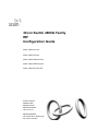
3Com Switch 4800G Family
IRF
Configuration Guide
Switch 4800G 24-Port
Switch 4800G 48-Port
Switch 4800G PWR 24-Port
Switch 4800G PWR 48-Port
Switch 4800G 24-Port SFP
Product Version:
Release 2202
Manual Version:
6W102-20100630
www.3com.com
3Com Corporation
350 Campus Drive, Marlborough,
MA, USA 01752 3064
Copyright © 2009-2010, 3Com Corporation. All rights reserved. No part of this documentation may be
reproduced in any form or by any means or used to make any derivative work (such as translation,
transformation, or adaptation) without written permission from 3Com Corporation.
3Com Corporation reserves the right to revise this documentation and to make changes in content from time to
time without obligation on the part of 3Com Corporation to provide notification of such revision or change.
3Com Corporation provides this documentation without warranty, term, or condition of any kind, either implied
or expressed, including, but not limited to, the implied warranties, terms or conditions of merchantability,
satisfactory quality, and fitness for a particular purpose. 3Com may make improvements or changes in the
product(s) and/or the program(s) described in this documentation at any time.
If there is any software on removable media described in this documentation, it is furnished under a license
agreement included with the product as a separate document, in the hard copy documentation, or on the
removable media in a directory file named LICENSE.TXT or !LICENSE.TXT. If you are unable to locate a copy,
please contact 3Com and a copy will be provided to you.
UNITED STATES GOVERNMENT LEGEND
If you are a United States government agency, then this documentation and the software described herein are
provided to you subject to the following:
All technical data and computer software are commercial in nature and developed solely at private expense.
Software is delivered as “Commercial Computer Software” as defined in DFARS 252.227-7014 (June 1995) or
as a “commercial item” as defined in FAR 2.101(a) and as such is provided with only such rights as are
provided in 3Com’s standard commercial license for the Software. Technical data is provided with limited rights
only as provided in DFAR 252.227-7015 (Nov 1995) or FAR 52.227-14 (June 1987), whichever is applicable.
You agree not to remove or deface any portion of any legend provided on any licensed program or
documentation contained in, or delivered to you in conjunction with, this User Guide.
Unless otherwise indicated, 3Com registered trademarks are registered in the United States and may or may
not be registered in other countries.
3Com and the 3Com logo are registered trademarks of 3Com Corporation.
All other company and product names may be trademarks of the respective companies with which they are
associated.
ENVIRONMENTAL STATEMENT
It is the policy of 3Com Corporation to be environmentally-friendly in all operations. To uphold our policy, we
are committed to:
Establishing environmental performance standards that comply with national legislation and regulations.
Conserving energy, materials and natural resources in all operations.
Reducing the waste generated by all operations. Ensuring that all waste conforms to recognized environmental
standards. Maximizing the recyclable and reusable content of all products.
Ensuring that all products can be recycled, reused and disposed of safely.
Ensuring that all products are labeled according to recognized environmental standards.
Improving our environmental record on a continual basis.
End of Life Statement
3Com processes allow for the recovery, reclamation and safe disposal of all end-of-life electronic components.
Regulated Materials Statement
3Com products do not contain any hazardous or ozone-depleting material.
Environmental Statement about the Documentation
The documentation for this product is printed on paper that comes from sustainable, managed forests; it is fully
biodegradable and recyclable, and is completely chlorine-free. The varnish is environmentally-friendly, and the
inks are vegetable-based with a low heavy-metal content.
About This Configuration Guide
Organization
The IRF Configuration Guide comprises one part:
Content
IRF Configuration
Conventions
The manual uses the following conventions:
Command conventions
Convention
Description
Boldface
The keywords of a command line are in Boldface.
italic
Command arguments are in italic.
[]
Items (keywords or arguments) in square brackets [ ] are optional.
{ x | y | ... }
Alternative items are grouped in braces and separated by vertical bars.
One is selected.
[ x | y | ... ]
Optional alternative items are grouped in square brackets and
separated by vertical bars. One or none is selected.
{ x | y | ... } *
Alternative items are grouped in braces and separated by vertical bars.
A minimum of one or a maximum of all can be selected.
[ x | y | ... ] *
Optional alternative items are grouped in square brackets and
separated by vertical bars. Many or none can be selected.
&<1-n>
The argument(s) before the ampersand (&) sign can be entered 1 to n
times.
#
A line starting with the # sign is comments.
GUI conventions
Convention
Description
<>
Button names are inside angle brackets. For example, click <OK>.
[]
Window names, menu items, data table and field names are inside
square brackets. For example, pop up the [New User] window.
/
Multi-level menus are separated by forward slashes. For example,
[File/Create/Folder].
Symbols
Convention
Description
Means reader be extremely careful. Improper operation may cause
bodily injury.
Means reader be careful. Improper operation may cause data loss or
damage to equipment.
Means a complementary description.
Related Documentation
In addition to this manual, each 3com Switch 4800G documentation set includes the following:
Manual
3Com Switch 4800G Family Getting
Started Guide
Description
Provides all information you need to install and use the
3Com Switch 4800G Family.
Describe how to configure your 4800G Switch using the
supported protocols and CLI commands. The 3Com
switch 4800G family documentation set includes 10
configuration guides:
1. Fundamentals Configuration Guide
2. IRF Configuration Guide
3Com Switch 4800G Family
Configuration Guides
3. Layer 2 – LAN Switching Configuration Guide
4. Layer 3 – IP Services Configuration Guide
5. Layer 3 – IP Routing Configuration Guide
6. IP Multicast Configuration Guide
7. ACL and QoS Configuration Guide
8. Security Configuration Guide
9. High Availability Configuration Guide
10. Network Management and Monitoring Configuration Guide
Describes command line interface (CLI) commands and
syntax options available on the switch. The 3Com switch
4800G family documentation set includes 10 command
references:
1. Fundamentals Command Reference
2. IRF Command Reference
3Com Switch 4800G Family Command
References
3. Layer 2 – LAN Switching Command Reference
4. Layer 3 – IP Services Command Reference
5. Layer 3 – IP Routing Command Reference
6. IP Multicast Command Reference
7. ACL and QoS Command Reference
8. Security Command Reference
9. High Availability Command Reference
10. Network Management and Monitoring Command Reference
Obtaining Documentation
You can access the most up-to-date 3Com product documentation on the World Wide Web at this URL:
http://www.3com.com.
Table of Contents
1 IRF Configuration ······································································································································1-1
IRF Overview ··········································································································································1-1
Introduction······································································································································1-1
Advantages······································································································································1-1
Application ·······································································································································1-2
Basic Concepts ·······································································································································1-2
Working Process ·····································································································································1-3
Physical Connections ······················································································································1-3
Topology Collection ·························································································································1-8
Role Election ···································································································································1-8
IRF Virtual Device Management and Maintenance·········································································1-9
IRF Virtual Device Configuration Task List ···························································································1-14
Configuring IRF Virtual Device··············································································································1-14
Configuring IRF Ports ····················································································································1-14
Setting a Member ID for a Device ·································································································1-15
Specifying a Priority for a Member Device ····················································································1-16
Specifying the Preservation Time of the Bridge MAC Address·····················································1-16
Enabling Auto Upgrade of Boot Files ····························································································1-17
Setting the Delay Time for the Link Layer to Report a Link-Down Event······································1-18
Accessing an IRF Virtual Device···········································································································1-19
Accessing the Master ····················································································································1-19
Accessing a Slave ·························································································································1-19
Displaying and Maintaining an IRF Virtual Device················································································1-20
IRF Virtual Device Configuration Examples··························································································1-20
IRF Virtual Device Configuration Example ····················································································1-20
2 Index ···························································································································································2-1
i
1
IRF Configuration
When configuring IRF, go to these sections for information you are interested in:
z
IRF Overview
z
Basic Concepts
z
Working Process
z
IRF Virtual Device Configuration Task List
z
Configuring IRF Virtual Device
z
Accessing an IRF Virtual Device
z
Displaying and Maintaining an IRF Virtual Device
z
IRF Virtual Device Configuration Examples
IRF Overview
Introduction
Developed by 3Com, Intelligent Resilient Framework (IRF) provides a new method to connect multiple
devices through physical IRF ports. Individual devices join to form a distributed device called IRF virtual
device. IRF realizes the cooperation, unified management, and non-stop maintenance of multiple
devices.
Advantages
IRF features the following advantages:
z
Streamlined management. When an IRF virtual device is established, you can log in to it by
connecting to any port of any member to manage all members of the IRF virtual device.
z
High reliability. An IRF virtual device comprises multiple member devices: the master runs,
manages and maintains the IRF virtual device, whereas the slaves process services as well as
functioning as the backups. As soon as the master fails, the IRF virtual device immediately elects a
new master immediately to prevent service interruption and implement 1:N redundancy. In addition,
not only the IRF links of members can be aggregated, but also the physical links between the IRF
virtual device and the upper or lower layer devices can be aggregated, and thus the reliability of the
IRF virtual device is increased through link redundancy.
z
Powerful network expansion capability. By adding member devices, the number of IRF ports and
network bandwidth of an IRF virtual device can be easily expanded. Each member device has its
own CPU and they can process and forward protocol packets independently. Therefore, the
processing capability of the IRF virtual device also can be easily expanded.
1-1
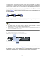
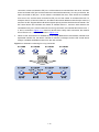
Application
As shown in Figure 1-1, a master and a slave form an IRF virtual device, which is a single device to the
upper and lower layer devices.
Figure 1-1 IRF networking
IP network
IP network
Slave
Master
IRF link
Equal to
IRF virtual device
Basic Concepts
Role
The devices that form an IRF virtual device are called member devices. Each of them plays either of the
following two roles:
z
Master: Manages the IRF virtual device.
z
Slave: All members that operate as the backups of the master are called slaves. When the master
fails, the IRF virtual device automatically elects a new master from one of the slaves.
Master and slaves are elected through the role election mechanism. An IRF virtual device has only one
master at a time. Other members are the slaves. For more information about election process, see Role
Election.
IRF port
An IRF port is a logical port dedicated to the internal connection of an IRF virtual device. An IRF port
can be numbered as IRF-port1 or IRF-port2. An IRF port is effective only after it is bound to a physical
IRF port.
Physical IRF port
Physical ports used for connecting members of an IRF virtual device are called physical IRF ports.
Physical IRF ports can be ports dedicated to the IRF virtual device, Ethernet ports or optical ports
(which port can serve as physical IRF ports depends on the device model.).
Typically, an Ethernet port or optical port forwards packets to the network. When bound to an IRF port,
it acts as a physical IRF port and forwards data traffic such as IRF-related negotiation packets and data
traffic among member devices.
1-2
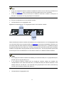
IRF virtual device merge
As shown in Figure 1-2, two IRF virtual devices operate independently and steadily. Connect them
physically and perform necessary configurations to make them form one IRF virtual device, and this
process is called IRF virtual device merge.
Figure 1-2 IRF virtual device merge
IRF virtual device partition
As shown in Figure 1-3, when an IRF virtual device is formed, the failure of the IRF link causes physical
disconnection between the two members, and then the IRF virtual device is divided into two IRF virtual
devices. This process is called IRF virtual device partition.
Figure 1-3 IRF virtual device partition
Member priority
Member priority determines the role of a member during a role election process. A member with a
higher priority is more likely to be a master. The priority of a device defaults to 1. You can modify the
priority at the command line interface (CLI).
Working Process
IRF virtual device management involves four stages: Physical Connections, Topology Collection, Role
Election and IRF Virtual Device Management and Maintenance. First physically connect the members
of an IRF virtual device, and then the members perform topology collection and role election to
establish an IRF virtual device, which then enters the IRF virtual device management and maintenance
stage.
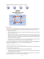
Physical Connections
Connection medium
To establish an IRF virtual device, physically connect the physical IRF ports of member devices. For the
Switch 4800G series, the 10 GE interface modules can be inserted into the expansion module slots on
the rear panel of the switch to provide physical IRF ports. The following 10 GE interface modules can
be used to provide physical IRF ports:
z
One-port 10 GE XFP interface module
z
Dual-port 10 GE XFP interface module
1-3
z
Short-haul dual-port 10 GE CX4 interface module
z
Dual-port 10 GE SFP+ interface module
For more information about an interface module, refer to its user manual.
You can connect physical IRF ports of the Switch 4800G series with either the CX4/SFP+ dedicated
cables or fibers according to the interface type on the interface module. Dedicated cables provide
higher reliability and performance; whereas fibers connect physical devices located very far from each
other and provide flexible application.
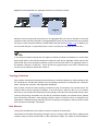
The physical IRF ports are numbered according to their physical locations on the rear panel of the
Switch 4800G series. With the rear panel facing you, the physical IRF ports are numbered successively
from left to right: ports on the interface module in slot 1 are numbered 1 and 2, and ports on the
interface module in slot 2 are numbered 3 and 4, as shown in Figure 1-4, which illustrates an example
of inserting a CX4 dual-port interface module.
Figure 1-4 Numbering physical IRF ports
If you insert a one-port interface module into the slot, then the number of the physical IRF port
corresponding to the module in slot 1 is 1, and the number of the physical IRF port corresponding to the
module in slot 2 is 3. For the number of physical IRF ports, see Configuring IRF Ports.
Physical IRF ports can be used for both IRF connection and service data transmission. When
establishing an IRF virtual device, you need to specify that the physical IRF ports are used for the IRF,
that is, bind them with IRF port(s) to implement IRF connection and establishment.
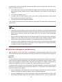
Connection requirements
As shown in Figure 1-5, IRF-Port1 on one device can only be connected to the physical port bound to
IRF-Port2 of a neighbor device; otherwise, an IRF virtual device cannot be formed.
1-4
Figure 1-5 IRF virtual device physical connection
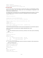
IRF topology
An IRF virtual device typically adopts daisy chain connection or ring connection, as shown in Figure
1-6.
z
A daisy chain connection is mainly used in a network where member devices are distributedly
located.
z
A ring connection is more reliable than the daisy chain connection. In a daisy chained IRF virtual
device, the failure of one link can cause the IRF virtual device to partition into two independent IRF
virtual devices; where the failure of a link in a ring connection result in a daisy chain connection, not
affecting IRF services.
Figure 1-6 IRF connections
You can connect at most nine Switch 4800G series switches to form an IRF virtual device.
Correspondence between an IRF port and a physical IRF port
The connection of IRF ports is based on that of physical IRF ports; therefore, you need to bind an IRF
port with physical IRF port(s). An IRF port can be bound to one physical IRF port or, to realize link
backup and bandwidth expansion, bound to two physical IRF ports (aggregated as an aggregate IRF
port).
1-5
You need to specify the correspondence between an IRF port and physical IRF port(s) through
command line. When you specify that an IRF port is bound to one physical IRF port, the serial number
of the physical IRF port bound to IRF port 1 must be smaller than that of the physical IRF port bound to
IRF port 2; when you specify that an IRF port is bound to two physical IRF ports (aggregate IRF port),
these two physical IRF ports must be on the same module.
As shown in Figure 1-7. Switch A connects to Switch B and Switch C through IRF ports IRF-port 1 and
IRF-port 2 respectively.
Figure 1-7 IRF port correspondence
Based on the type and number of the interface module inserted on Switch A, you can adopt one of the
following typical correspondences to establish an IRF connection.
z
The dual-port 10 GE CX4 interface module is used in the following examples to introduce
correspondence between the IRF port and the physical IRF port(s).
z
When the dual-port 10 GE SFP interface module is used, the correspondence between the IRF
port and the physical IRF port(s) is similar.
2)
IRF port correspondence for one interface module
Figure 1-8 IRF port correspondence for one interface module
When a dual-port interface module is installed, you need to bind IRF-port 1 to physical IRF port 1, and
IRF-port 2 to physical IRF port 2 (as shown in Figure 1-8), because the serial number of the physical
IRF port bound to IRF-port 1 must be smaller than that of the physical IRF port bound to IRF-port 2.
Therefore, you cannot bind IRF-port 1 to physical IRF port 2, and IRF-port 2 to physical port 1.
1-6
z
If only one single-port interface module is installed, the device can be used only as Switch B or
Switch C in Figure 1-7, that is, the device should be at either end of a bus connection.
z
In this situation, because only one IRF port is needed on Switch B or Switch C, IRF-port 2 or
IRF-port 1 can be bound to any physical port on the device.
3)
IRF port correspondence for two interface modules
z
Correspondence in non-aggregate mode
Figure 1-9 Correspondence in non-aggregate mode for two interface modules
When two dual-port interface modules are installed, if the correspondence is not in the aggregate mode,
you can bind an IRF port to any physical IRF port (Figure 1-9 only shows one possibility). However, you
must ensure that the serial number of the physical IRF port bound to IRF-port 1 is smaller than that of
the physical IRF port bound to IRF-port 2, namely, the physical IRF port bound to IRF-port 2 should be
located on the right side of the physical IRF port bound to IRF-port 1. The two physical IRF ports bound
to the IRF ports can be located either on one interface module or on different interface modules.
z
If two single-port interface modules are installed, you need to bind IRF-port 1 to physical IRF port 1,
and IRF-port 2 to physical IRF port 3.
z
If one dual-port interface module and one single-port interface module are installed, the
correspondence is the same with that when you install two dual-port interface modules. In this
situation, IRF-port 2 or IRF-port 1 can be bound to any physical port on the device, because only
one IRF port is needed on Switch B or Switch C.
z
Correspondence in aggregate mode
1-7
Figure 1-10 Correspondence in aggregate mode for two interface modules
Because the two physical IRF ports bound to an aggregate IRF port must be located on the same
interface module, two IRF ports (that is, two aggregate IRF ports) can only be bound to the two physical
IRF ports on each of the two interface modules respectively (as shown in Figure 1-10). In addition, you
can only bind IRF-port 1 to physical IRF ports 1 and 2, and IRF-port 2 to physical ports 3 and 4.
If one dual-port interface module and one single-port interface module are installed, you can bind two
physical IRF ports on the dual-port interface module to the IRF port in aggregate mode, and bind the
physical IRF port on the single-port interface module to the other IRF port in non-aggregate mode. In
this situation, IRF-port 2 or IRF-port 1 can be bound to any physical port on the device, because only
one IRF port is needed on Switch B or Switch C.
Topology Collection
Each member exchanges hello packets with the directly connected neighbors to collect topology of the
IRF virtual device. The IRF hello packets carry the topology information, including IRF port connection
states, member IDs, priorities, and bridge MAC addresses.
Each member records its known topology information locally. At the startup of a member device, the
member device records topology information of the local device. When an IRF port of a member
becomes up, the member device sends its known topology information from this port periodically. Upon
receiving the topology information from the directly connected neighbor, the member device updates
the local topology information. After topology collection lasts for a period of time, all members have
obtained the complete topology information (known as topology convergence), and then the IRF virtual
device enters the next stage: role election.
Role Election
The process of defining the role (master or slave) of members is role election.
Role election is held when the topology changes, such as, forming an IRF virtual device, adding a new
member, leaving or failure of the master, or IRF virtual device merge. The master is elected based on
1-8
the rules below, in the order specified. If the first rule does not apply, a second rule is tried, and so on,
until the only winner is found.
z
The current master, even if a new member has a higher priority. (When an IRF virtual device is
being formed, and all member devices consider themselves as the master, so this principle is
skipped)
z
A member with a higher priority.
z
A member with the longest system up-time. (The system up-time information of each member
device is delivered through IRF hello packets)
z
A member with the lowest bridge MAC address.
Then, the IRF virtual device is formed and enters the next stage: IRF virtual device management and
maintenance.
z
The precision of the system up-time is six minutes. For example, if two devices with the same
priority values reboot one after another within six minutes, they will have the same system up-time
and the last role election principle will be followed, that is, the one with the lowest bridge MAC
address wins.
z
During an IRF virtual device merge, an IRF election is held, and role election rules are followed.
Members of the loser side reboot and join the winner side as slaves. Whether the device reboots
automatically or reboots with the execution of a command depends on the device model.
z
To ensure the same configuration as that on the master, a device uses the master’s configuration
to initialize and boot itself as long as it is elected as a slave, regardless of its original configuration
or whether its current configuration is saved.
IRF Virtual Device Management and Maintenance
After role election, an IRF virtual device is established: all member devices operate as one virtual
device, and all resources on the member devices are processed by this virtual device and managed by
the master.
Member ID
An IRF virtual device uses member IDs to uniquely identify and manage its members. For example,
when the device operates independently, the slot number in the interface number is typically 1; after it
joins an IRF virtual device, the slot number will become the member ID. In addition, member IDs are
used in file management. Therefore, member IDs in an IRF virtual device must be unique.
If member IDs are not unique, an IRF virtual device cannot be established. A member having the same
member ID as an existing one cannot join the IRF virtual device. To ensure the uniqueness of member
IDs, use the following two methods:
1)
Before establishing an IRF virtual device, plan and configure member IDs for members. Adopt the
member ID collision processing mechanism, which is described as follows:
z
During the establishment of an IRF virtual device, when two devices that form the IRF virtual
device have duplicated member IDs, the master is numbered the first. Then, for a daisy chain
1-9
connection, slaves connected to IRF port 1 of the master are numbered from near to far, and then
those connected to IRF port 2 of the master are numbered the same way; for a ring connection, the
slave connected to IRF port 1 of the master is numbered first, then, other slaves are numbered
from near to far, and the slave connected to IRF port 2 of the master is numbered the last. For
example, Device A, Device B, Device C, and Device D use their default member IDs (the value is 1)
and form an IRF. Suppose Device B has the highest priority and thus is elected as the master. The
IRF virtual device first numbers the master as member device 1, and then other devices are
numbered one by one. If the four devices form a ring connection, the member IDs of them are 2, 1,
3, and 4, as shown in Figure 1-11; if the four devices form a daisy chain connection, the member
IDs of them are 2, 1, 4, and 3, as shown in Figure 1-12.
z
When an IRF virtual device is established, if the newly added device and another member have
duplicated member IDs, the latter’s member ID remains unchanged, and the IRF virtual device
assigns a smallest available member ID to the new member.
Figure 1-11 Automatic numbering for a ring connection
1-10
Figure 1-12 Automatic numbering for a daisy chain connection
MemberID=1
MemberID=1
MemberID=1
MemberID=1
Device A
Device B
Device C
Device D
Suppose Device
B is elected as
the master when
the IRF virtual
device is formed.
MemberID=3
MemberID=2
Device A
(Slave)
Device D
(Slave)
IRF-Port1
IRF-Port2
MemberID=1
MemberID=4
Device B
(Master)
Device C
(Slave)
Interface name
For a device operating independently (that is, the device does not belong to any IRF virtual device), its
interface name is in the following format: member ID/slot number/interface serial number, where
z
By default, member ID is 1.
z
After a device leaves an IRF virtual device, it continues using the member ID when it was in the IRF
virtual device as its device ID.
z
Subslot number is the number of the slot in which the LPU resides. For a box-type device, LPUs
are fixed on the device, so the slot number is a fixed value. On the Switch 4800G series, the
subslot on the front panel is numbered 0, and subslots of the two expansion slots on the rear panel
are numbered 1 and 2 from left to right.
z
Interface serial number is dependent on the number of interfaces supported by the device. View
the silkscreen on the interface card for the number of supported interfaces.
For example, GigabitEthernet 1/0/1 is an interface on the independently operating device Sysname. To
set the link type of GigabitEthernet 1/0/1 to trunk, perform the following steps:
<Sysname> system-view
[Sysname] interface gigabitethernet 1/0/1
[Sysname-GigabitEthernet1/0/1] port link-type trunk
For an IRF member, the interface name also adopts the previously introduced format: member ID/slot
number/interface serial number, where
z
The member ID identifies the IRF member on which the interface resides
z
Meaning and value of the subslot number and the interface serial number are the same as those
on an independently operating device.
For example, Ethernet 1/0/1 is an interface on IRF member slave 3 (member ID is 3). To set the link
type of GigabitEthernet 1/0/1 to trunk, perform the following steps:
1-11
<Master> system-view
[Master] interface gigabitethernet 3/0/1
[Master-GigabitEthernet3/0/1] port link-type trunk
File system name
You can use the name of the storage device to access the file system of an independently operating
device. For the naming rules of a storage device, see File Management Configuration in the
Fundamentals Configuration Guide.
For example, flash is the storage device on the independently operating device Sysname. To back up
the file aa.cfg under the root directory of the flash to the test folder, perform the following steps:
<Sysname> mkdir test
...
%Created dir flash:/test.
<Sysname>copy aa.cfg test/aa(20080714).cfg
Copy flash:/aa.cfg to flash:/test/aa(20080714).cfg?[Y/N]:y
..
%Copy file flash:/aa.cfg to flash:/test/aa(20080714).cfg...Done.
<Sysname> cd test
<Sysname> dir
Directory of flash:/test/
0
-rw-
1568
Jul 14 2008 11:54:04
aa(20080714).cfg
30861 KB total (20956 KB free)
To access the file system of the master, use the name of the storage device; to access the file system of
a slave, use the name in the following format: Member-ID#Storage-device-name.
For example:
1)
To access the test folder under the root directory of the flash on the master, perform the following
steps:
<Master> mkdir test
...
%Created dir flash:/test.
<Master> dir
Directory of flash:/
0
-rw-
10105088
Apr 26 2000 13:44:57
test.bin
1
-rw-
2445
Apr 26 2000 15:18:19
config.cfg
2
drw-
-
Jul 14 2008 15:20:35
test
30861 KB total (20961 KB free)
2)
To create and access the test folder under the root directory of the flash on IRF member slave 3,
perform the following steps:
<Master> mkdir slot3#flash:/test
%Created dir slot3#flash:/test.
<Master> cd slot3#flash:/test
<Master> pwd
slot3#flash:/test
Or:
<Master> cd slot3#flash:/
<Master> mkdir test
%Created dir slot3#flash:/test.
1-12
3)
To copy the test.bin file on the master to the root directory of the flash on IRF member slave 3,
perform the following steps:
<Master> pwd
slot3#flash:
//The above information indicates that the current working path is the root directory of the flash on slave
3.
<Master> cd flash:/
<Master> pwd
flash:
// The above operations indicate that the current working path is the root directory of the flash on the
master.
<Master> copy test.bin slot3#flash:/
Copy flash:/test.bin to slot3#flash:/test.bin?[Y/N]:y
%Copy file flash:/test.bin to slot3#flash:/test.bin...Done.
Configuration file management
1)
Configuration file synchronization
IRF uses a strict configuration file synchronization mechanism to ensure that devices in an IRF virtual
device can work as a single device on the network, and to ensure that after the master fails, the other
devices can operate normally.
z
When a slave starts up, it automatically finds out the master, synchronizes the master's
configuration file, and executes the configuration file; if all devices in an IRF virtual device start up
simultaneously, the slaves synchronize the master's initial configuration file and execute it.
z
When the IRF virtual device operates normally, all your configurations will be recorded into the
current configuration file of the master, and are synchronized to each device in the IRF virtual
device; when you save the current configuration file of the master as the initial configuration file by
using the save command, all slaves execute the same saving operation to make the initial
configuration files of all devices consistent.
Through the real-time synchronization, all devices in the IRF virtual device keep the same configuration
file. If the master fails, all the other devices can execute various functions according to the same
configuration file.
2)
Configuration file application
The configuration file can be divided into two parts: global configuration and port configuration. When a
slave applies these two kinds of configurations of the master, it deals with them in different ways:
z
Global configuration: All slaves execute the current global configuration on the master exactly, that
is, all members in the IRF virtual device apply the same global configuration.
z
Port configuration: When a slave applies the port configuration on the master, it cares about the
configuration related to its own port, for example, the slave with the member ID of 3 only cares
about the configuration related to the GigabitEthernet 3/0/x port on the master. If there is a
configuration related to its own port, it will apply the configuration; if not, no matter what
configuration has been made to the port before the slave joins the IRF virtual device, the slave will
function using null-configuration.
IRF virtual device topology maintenance
In an IRF, direct neighbors exchange hello packets periodically (the period is 200 ms). Without
receiving any hello packet from a direct neighbor for ten periods, a member considers that the hello
1-13
packets timed out, and the IRF isolates the expired device in the topology and updates its topology
database.
When an IRF port of a member becomes down, the member broadcasts the information to all the other
members immediately. If the IRF port of the master is down, an election is triggered.
IRF Virtual Device Configuration Task List
Before configuring an IRF virtual device, you need to define the roles and functions of all the members
for better planning. Because the configuration of some parameters takes effect after device reboot, you
are recommended to first configure parameters, power off the devices, connect devices physically,
power on the devices, and finally the devices will join in the IRF virtual device automatically. After an
IRF virtual device is formed, you can configure and manage the IRF virtual device by logging in to any
device in the IRF virtual device. The operations you make take effect on the master, and will be applied
to the member devices in the IRF virtual device. For easy fault location and device maintenance, the
Switch 4800G series provide slave view, where you can execute the display, terminal, and debug
commands.
Complete the following tasks to configure IRF:
Task
Configuring IRF Virtual
Device
Remarks
Configuring IRF Ports
Required
Setting a Member ID for a Device
Optional
Specifying a Priority for a Member Device
Required
Specifying the Preservation Time of the Bridge MAC
Address
Optional
Enabling Auto Upgrade of Boot Files
Optional
Setting the Delay Time for the Link Layer to Report a
Link-Down Event
Optional
Connect the physical IRF ports of devices by using IRF cables (a ring connection is recommended) or fibers,
and then power on the devices.
Accessing an IRF Virtual
Device
Accessing the Master
Required
Accessing a Slave
Optional
Configuring IRF Virtual Device
Configuring IRF Ports
IRF ports are logical. IRF can be enabled on a device only after the IRF ports are configured (in other
words, the IRF ports are bound to physical IRF ports).
For how to bind the IRF port and physical IRF port(s) on a Switch 4800G series, see Correspondence
between an IRF port and a physical IRF port.
Follow these steps to configure IRF ports
To do…
Enter system view
Use the command…
system-view
1-14
Remarks
—
To do…
Bind physical IRF ports to an IRF
port, and enable IRF on the
current device
Use the command…
irf member member-id irf-port
irf-port-id port port-list
Remarks
Required
By default, no IRF port is
configured.
z
The above configuration takes effect after the reboot of the device.
z
An IRF port that is bound with multiple physical IRF ports is an aggregation IRF port, which
increases the bandwidth and reliability on the IRF port. If you specify multiple physical IRF ports
with the port-list argument, you can configure an aggregation IRF port. You can configure at most
two physical IRF ports as an aggregation IRF port for a Switch 4800G series switch, and you can
only aggregate physical IRF ports 1 and 2, and physical IRF ports 3 and 4.
z
The irf-port-id argument represents the IRF port number. The port-list argument represents the
physical IRF port number. For the correspondence of IRF ports, refer to Correspondence between
an IRF port and a physical IRF port.
z
When you insert a one-port interface module into the slot on the rear panel, if the interface module
is in slot 1, the port on it will be numbered 1; and if the interface module is in slot 2, the port on it will
be numbered 3.
Setting a Member ID for a Device
The member ID of a device defaults to 1. During the establishment of an IRF virtual device, when the
devices that form the IRF have duplicated member IDs, the member ID of the master is decided first,
and then the member IDs of slaves are decided by the member ID collision processing mechanism.
After the IRF virtual device is established, if the newly added device and another member have
duplicated IDs, the IRF system assigns the smallest available ID for the new member. You can also set
the member IDs according to network planning.
For a device that is already in an IRF virtual device, you can use commands in Table 1-1 to modify the
member ID of the device, and this modification will be effective after the reboot of the device.
For a device that is not in an IRF virtual device, you are recommended to set its member ID in the
following way:
1)
Plan the member IDs in advance. You can view the member IDs of an IRF virtual device, and find
out an unused ID for the new device.
2)
Log in to the device to be added into the IRF virtual device, and change its member ID to the
unused ID found out in step 1.
3)
Save the current configuration. Power off the device, connect the device with IRF cables and
power it on. Use the configuration introduced in this section to enable IRF on the device and add it
into the IRF virtual device.
1-15
Table 1-1 Set a member ID for a device
To do…
Use the command…
Enter system view
system-view
Set a member ID for a device
irf member member-id renumber
new-id
Remarks
—
Optional
The member ID of a device
defaults to 1
z
The above setting takes effect after the reboot of the device.
z
You can use the display irf configuration command to view the current member ID of the device
and the member ID will be used after the device reboot.
z
Members IDs are used to identify members of an IRF virtual device. Therefore, modifying a
member ID may cause device configuration change or even loss. Please modify member IDs with
caution. For example, three members (of the same device model) with the member IDs of 1, 2 and
3 are connected to an IRF port. Suppose that each member has several ports: change the member
ID of device 2 to 3, change that of device 3 to 2, reboot both devices, and add them into the IRF
virtual device again. Then device 2 will use the original port configurations of device 3, and device
3 will use those of device 2.
Specifying a Priority for a Member Device
The greater the priority value, the higher the priority. A member with a higher priority is more likely to be
a master.
Follow these steps to specify a priority for a member device:
To do…
Use the command…
Enter system view
system-view
Specify a priority for a member of
an IRF virtual device
irf member member-id priority
priority
Remarks
—
Optional
The priority of a member defaults
to 1
The setting of priority takes effect right after your configuration without the need of rebooting the device.
Specifying the Preservation Time of the Bridge MAC Address
A device uses the bridge MAC address when it communicates with the external networks as a bridge.
Some Layer 2 protocols (like LACP) use bridge MAC addresses to identify different devices. During of
Layer 2 packet forwarding, if the destination MAC address of a packet is the bridge MAC address of a
1-16
device, the packet is sent to this device; otherwise, the packet is discarded. Therefore, a bridge device
on your network must have a unique bridge MAC address. If two devices on your network have the
same bridge MAC addresses, bridge MAC address collision occurs and the communication fails.
An IRF virtual device communicates with external networks as a single device; therefore, it also has a
bridge MAC address. Typically, an IRF virtual device uses the bridge MAC address of the master as its
bridge MAC address.
Bridge MAC address collision causes communication failure, and bridge MAC address switching
causes traffic interruption. Therefore, configure the preservation time of the bridge MAC address of the
IRF virtual device:
z
Preserve for six minutes: When the master leaves, the bridge MAC address does not change
within six minutes. If the master does not come back when the preserve time is expired, the IRF
virtual device uses the bridge MAC address of the newly elected master as its bridge MAC address.
If the master leaves the IRF for a short time due to device reboot or link failure, this configuration
can reduce unnecessary switch of bridge MAC address and thus avoid traffic interruption.
z
Preserve permanently: No matter whether the master leaves the IRF virtual device or not, the
bridge MAC address of the IRF virtual device remains unchanged.
z
Not preserved: As soon as the master leaves, the IRF virtual device uses the bridge MAC address
of the newly elected master as its bridge MAC address.
Follow these steps to specify the preservation time of the bridge MAC address of an IRF virtual device:
To do…
Use the command…
Enter system view
system-view
Configure the bridge MAC address of the
IRF virtual device to be preserved
permanently when the master leaves
irf mac-address persistent always
Remarks
—
Optional
Specify the preservation time of the bridge
MAC address of the IRF virtual device as 6
minutes when the master leaves
irf mac-address persistent timer
Configure that the bridge MAC address of
the IRF virtual device changes as soon as
the master leaves
undo irf mac-address persistent
By default, IRF bridge
MAC address is
preserved for 6
minutes after the
master leaves.
z
Bridge MAC address change may cause a temporary traffic interruption.
z
If two IRF virtual devices have the same bridge MAC address, they cannot be merged into one IRF
virtual device.
Enabling Auto Upgrade of Boot Files
z
If auto upgrade of boot files is disabled, when the software of slaves and that of the master are in
different versions, the new member or the member with a low priority will not boot normally. Update
the device version and add the device into the IRF virtual device again.
1-17
z
If auto upgrade of boot file is enabled, as soon as a device is added into an IRF virtual device, the
IRF virtual device compares its software version with that of the master. If the versions are not
consistent, the device automatically downloads the boot file from the master, reboots with the new
boot file, and joins the IRF virtual device again. If the downloaded boot file and the local boot file
have duplicate file names, the local file is overwritten.
Follow these steps to enable auto upgrade of boot files for an IRF virtual device:
To do…
z
Use the command…
Enter system view
system-view
Enable auto upgrade of boot files
for an IRF virtual device
irf auto-update enable
Remarks
—
Optional
Enabled by default
Although IRF supports the auto upgrade of boot files, to shorten the time for IRF virtual device
establishment and reduce the influences caused by the IRF virtual device establishment to the
network, you are recommended to ensure that the device and the master have the same software
version before adding a device into an IRF virtual device.
z
After automatically loading the master’s boot file, a slave configures the file as the boot file to be
used at the next boot and reboots automatically.
z
To make the auto upgrade succeed, ensure that there is enough space on the storage media of the
slave.
Setting the Delay Time for the Link Layer to Report a Link-Down Event
After you set the delay time for the link layer to report a link-down event:
z
If the IRF link state changes from up to down, the port does not immediately report the link state
changes to the IRF virtual device. If the IRF link state is still down when the configured time is
reached, the port reports the link state changes to the IRF virtual device, which then handles the
problem accordingly.
z
If the link state changes from down to up, the link layer immediately reports the event to the IRF
virtual device .
Use this function to avoid unnecessary IRF virtual device partition and merge caused by frequent link
state changes of a port in a short time.
Follow these steps to set the delay time for the link layer to report a link-down event of an IRF virtual
device:
To do…
Use the command…
Enter system view
system-view
Set the delay time for the link
layer to report a link-down event
of an IRF virtual device
irf link-delay interval
Remarks
—
Optional
1-18
The function is disabled by
default.
Do not set the delay time to a very long time; otherwise, the IRF virtual device will not be aware of the
IRF topology changes in time and thus the service will be recovered slowly.
Accessing an IRF Virtual Device
Accessing the Master
Access an IRF virtual device in either of the following two ways:
z
Local login: Log in through the AUX or console port of a member device.
z
Remote login: Configure an IP address for a Layer 3 Ethernet interface of a member device and
make sure that the route is reachable, and then access the IRF virtual device remotely through
Telnet, Web, or SNMP.
When you log in to the IRF virtual device, actually you log in to the master. The master is the
configuration and control center of an IRF virtual device. When you configure the IRF virtual device on
the master, the IRF virtual device synchronizes the configurations to the slaves.
Accessing a Slave
When you log in to an IRF virtual device, actually you log in to the master. The operation interface of the
access terminal displays the master console. To print the logs or debugging information of a slave,
redirect to the specified slave device. After that, the user access terminal displays the console of the
slave device instead of that of the master device. The system enters user view of the salve device and
the command prompt is changed to <Sysname-Slave#X>, where X is the member ID of the device, for
example, <Sysname-Slave#2>. What you have input on the access terminal will be redirected to the
specified slave device for processing. At present, only the following commands are allowed to be
executed on a slave device:
z
display
z
quit
z
return
z
system-view
z
debugging
z
terminal debugging
z
terminal trapping
z
terminal logging
To return to the master console, use the quit command. At this time, the master console is reactivated
and can output logs.
Follow the step below to log in to the specified slave device:
1-19
To do…
Use the command…
Remarks
Required
Log in to the specified slave
device of an IRF virtual device
irf switch-to member-id
By default, you actually log in to the master
when you log in to the IRF virtual device.
Available in user view
Because users’ login to the IRF system occupies large memory space, an IRF system allows at most
six users to log in at the same time. The permitted login user types are console and virtual type terminal
(VTY).
Displaying and Maintaining an IRF Virtual Device
To do…
Use the command…
Remarks
Display related information about the IRF
virtual device
display irf
Available in any view
Display topology information about the IRF
virtual device
display irf topology
Available in any view
Display all members’ configurations that take
effect after device reboots
display irf configuration
Available in any view
Display the master/slave switchover states of
IRF members
display switchover state
[ member-id ]
Available in any view
IRF Virtual Device Configuration Examples
IRF Virtual Device Configuration Example
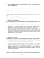
Network requirements
Three Switch 4800G series switches in an IRF form a daisy chain connection. Their member IDs are 1,
2, and 3, as shown in Figure 1-13.
1-20
Figure 1-13 Network diagram for IRF virtual device configuration example
1
2
3
4
Switch 1
1
2
3
4
Switch 2
1
2
3
4
Switch 3
Configuration procedure
1)
The three devices are not connected. Power them on and configure them separately.
# Configure Switch 1.
<Switch1> system-view
[Switch1] irf member 1 renumber 1
Warning: Renumbering the switch number may result in configuration change or loss.
Continue?[Y/N]:y
[Switch1] irf member 1 irf-port 1 port 2
# Configure Switch 2.
<Switch2>system-view
[Switch2] irf member 1 renumber 2
Warning: Renumbering the switch number may result in configuration change or loss.
Continue?[Y/N]:y
[Switch2] irf member 1 irf-port 1 port 2
[Switch2] irf member 1 irf-port 2 port 3
# Configure Switch 3.
<Switch3> system-view
[Switch3] irf member 1 renumber 3
Warning: Renumbering the switch number may result in configuration change or loss.
Continue?[Y/N]:y
[Switch3] irf member 1 irf-port 2 port 3
2)
Power off the three devices. Connect them as shown in Figure 1-13 with IRF cables. Power them
on,
and
the
IRF
virtual
1-21
device
is
formed
2
Index
A
Accessing a Slave
1-19
Accessing the Master 1-19
Advantages 1-1
Application 1-2
C
Configuring IRF Ports 1-14
E
Enabling Auto Upgrade of Boot Files
1-17
I
Introduction 1-1
IRF Virtual Device Configuration Example
1-20
IRF Virtual Device Management and
Maintenance
1-9
P
Physical Connections 1-3
R
Role Election
1-8
S
Setting a Member ID for a Device
1-15
Setting the Delay Time for the Link Layer to
Report a Link-Down Event 1-18
Specifying a Priority for a Member Device
1-16
Specifying the Preservation Time of the
Bridge MAC Address 1-16
T
Topology Collection 1-8
2-1