1
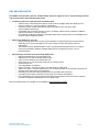
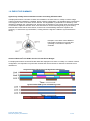
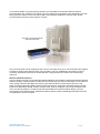
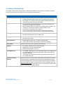
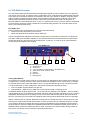
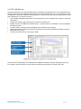
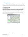
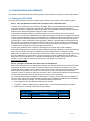
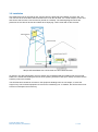
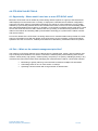
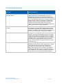
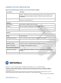
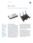
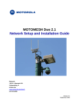
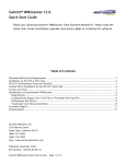
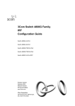
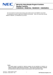
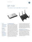
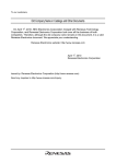
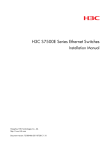
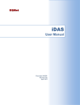
WIRELESS NETWORK SOLUTIONS PTP-SYNC Sales Guide – Rel. 08-50 Purpose and Scope The purpose of this Sales Guide is to equip Motorola account teams and authorized channel members with the information needed to effectively position and sell the Motorola PTP-SYNC unit for PTP 600 Series Wireless Ethernet Bridges. This is a living document that acts as a central point of reference regarding this release. To avoid information becoming out-of-date, this document may contain hyperlinks for access to other related sources of information. This Sales Guide is considered Motorola Confidential and Proprietary. It is permissible to extract certain sections or subsections that apply to specific customer situations. This document should not be used for contracts or proposals in lieu of an official Motorola customer d ocument. Acronym References CMM FIPS GPS LOS LPU nLOS NLOS NMEA NMS ODU PIDU PoE PPS PTP RF SNMP TDD Cluster Management Module Federal Information Processing Standard Global Positioning System Line-of-sight (clear line-of-sight and Fresnel zone is clear) Lightning Protection Unit, a surge arrestor Near-line-of-sight (clear line-of-sight but Fresnel zone is blocked) Non-line-of-sight (no line-of-sight and Fresnel zone is blocked) National Marine Electronics Association, the message protocol used by GPS receivers Network Management System Outdoor Unit Power Indoor Unit Power-over-Ethernet Pulse-per-second Point-to-Point Radio Frequency Simple Network Management Protocol Time Division Duplex KEY SELLING POINTS PTP-SYNC units provide a precise, reliable timing reference signal for use in synchronizing transmit and receive frames with PTP 600 Series links. Compelling reasons to purchase the PTP-SYNC Unit: o Overcome the cross interference that is common when multiple radios are deployed on a tower or rooftop or in a dense network configuration o Provide a precise, highly stable timing reference signal for the PTP 600’s TDD synchronization technology o Compatible with a number of timing sources, including a GPS receiver, Motorola’s CMM or other synchronized 1 Hz timing device o Can maintain local timing between collocated radios when a timing source is unavailable such as when a GPS satellite is off-line With a PTP-SYNC unit, you can: o Supply a timing reference to enable synchronization of radio transmit and receive frames o Collocate up to 10 PTP 600 radios on a single rooftop or tower with greatly reduced interference o Add a GPS receiver, Motorola CMM or other synchronized timing input device to support frame synchronization between multiple radios which are deployed on two or more towers/rooftops Why should a customer choose the PTP-SYNC unit? o Motorola-branded PTP synchronization unit o Optimized for use with PTP 600 Series radios o Only one PTP-SYNC unit is needed per link o Daisy chain up to 10 PTP-SYNC units from one timing source o Cost-effective unit o User-upgradable via software o Indoor mounted – requires no tower or rooftop climb to install units o Saves rack space – small-footprint device can be wall-mounted, rack-mounted or placed on a desktop where rack space is at a premium o Powering from the PoE cable between the PTP 600 PIDU Plus and ODU o PTP 600’s user interface shows the PTP-SYNC unit’s status and statistics o PTP LINKPlanner accurately predicts PTP 600 link performance with PTP-SYNC units and provides configuration parameters for PTP-SYNC units More information about PTP-SYNC Unit is available at www.motorola.com/ptp PTP-SYNC Sales Guide Motorola Proprietary & Confidential 2 of 18 TABLE OF CONTENTS 1.0 EXECUTIVE SUMMARY ........................................................................................................... 4 2.0 PRODUCT DESCRIPTION ........................................................................................................ 6 2.1 PTP-SYNC Overview ............................................................................................................. 7 2.2 PTP LINKPlanner ................................................................................................................... 8 2.3 Network Management ............................................................................................................ 9 3.0 CONFIGURATION AND ORDERING ...................................................................................... 10 3.1 Ordering the PTP-SYNC ...................................................................................................... 10 3.2 Installation ............................................................................................................................ 11 4.0 PTP-SYNC SALES TOOLS ..................................................................................................... 12 4.1 Opportunity – When would I need one or more PTP-SYNC units? ..................................... 12 4.2 Pain – What are the network management priorities? ......................................................... 12 4.3 Vision – What can I do with the PTP-SYNC? ...................................................................... 13 4.4 Benefits – Who will benefit from the PTP-SYNC purchase decision? ................................. 14 4.5 Competition – Competitive Advantages of PTP-SYNC Units .............................................. 15 4.6 Overcoming Objections........................................................................................................ 16 5.0 FREQUENTLY ASKED QUESTIONS ..................................................................................... 17 APPENDIX: PTP-SYNC SPECIFICATIONS ................................................................................. 18 PTP-SYNC Sales Guide Motorola Proprietary & Confidential 3 of 18 1.0 EXECUTIVE SUMMARY Opportunity: Greatly reduce interference when collocating PTP 600 radios In deployments where a number of radios are installed on the same tower or rooftop or where a large number of links are installed in a sizeable, dense network configuration, it is possible that the performance or throughput of some of the links can be reduced. The degradation in performance is caused by cross interference between the collocated units, and the level of interference can worsen when the links operate on the same or adjacent channels. Such cross interference can be reduced greatly by synchronizing transmit and receive frames of the radios, so that none are transmitting while their neighbors are receiving. To achieve this synchronization, a timing reference signal is needed to synchronize frame timing. Example: Three links of three different link lengths mounted on one mast and operating on the same or adjacent channels Solution: Motorola’s PTP-SYNC Unit for PTP 600 Series Bridges For deployments where several PTP 600 radios are deployed on a tower or rooftop or in a dense network configuration, it is important to synchronize transmit and receive frames to minimize or eliminate cross interference. Unsynchronized TDD Cycles with Significant Interference Synchronized TDD Cycles of Interfering Links PTP-SYNC Sales Guide Motorola Proprietary & Confidential 4 of 18 To provide a reliable, convenient timing reference for collocated PTP 600 links, Motorola offers a synchronization unit, called the PTP-SYNC. The PTP-SYNC Synchronization Unit is designed to provide timing reference signals for the PTP 600’s TDD synchronization capability to achieve frame timing synchronization across an entire network of radios. PTP 600 Connectorized Radio and PTP-SYNC Unit Only one PTP-SYNC unit is required per link, and you can daisy-chain up to 10 PTP-SYNC units together to share the timing information among a group of radios. The PTP LINKPlanner tool makes it easy to accurately predict link performance for links that are configured with PTP-SYNC units as the timing reference. Wireless Network Solutions The PTP-SYNC unit and PTP 600 Wireless Ethernet Bridges are included in Motorola’s Wireless Network Solutions portfolio. Motorola delivers seamless connectivity that puts real-time information in the hands of users, giving customers the agility they need to grow their business or better protect and serve the public. Working seamlessly together with its world-class devices, Motorola's unrivalled wireless network solutions include indoor WLAN, outdoor wireless mesh, point-to-multipoint, point-to-point networks and voice over WLAN solutions. Combined with powerful software for wireless network design, security, management and troubleshooting, Motorola's solutions deliver trusted networking and anywhere access to organizations across the globe. PTP-SYNC Sales Guide Motorola Proprietary & Confidential 5 of 18 2.0 PRODUCT DESCRIPTION PTP-SYNC units provide a timing reference signal that enables service providers and network operators to synchronize transmit and receive frames of collocated PTP 600 radios. PTP-SYNC High-Level Feature Set Timing Input Signal Configuration 1 Hz or 1 PPS (pulse-per-second) received from a timing device (GPS receiver, Motorola CMM or other 1 Hz synchronized timing source) PTP-SYNC can maintain local synchronization between collocated units when the timing source is unavailable One PTP-SYNC unit is required per link when collocated radios are mounted on a single tower or rooftop When PTP 600 radios are deployed on multiple towers/rooftops in the network, an external GPS receiver, Motorola CMM or other synchronized 1Hz timing input is required Up to 10 PTP-SYNC units can be daisy chained from one timing source (GPS receiver, CMM or other synchronized timing module) Powering 56 V DC Phantom powering from PIDU to ODU cable Cabling Standard RJ-45 connection Standard Cat 5e cable Easy Installation Small footprint, indoor unit – no tower or rooftop climb Can be wall-mounted, rack-mounted or placed on a desktop SYNC Status LED’s provide power status, GPS and SYNC activity Software PTP-SYNC contains its own internal software Optimized for use with PTP 600 radios Software upgradeable by the user PTP LINKPlanner PTP-SYNC configurations can be planned using the PTP LINKPlanner Accurately predicts PTP 600 link performance with a PTP-SYNC as the timing reference Thousands of PTP systems have been accurately planned using the PTP LINKPlanner tool 12-Month Standard Warranty PTP-SYNC Sales Guide Motorola Proprietary & Confidential With the purchase of a PTP-SYNC system Motorola provides a 12-month limited warranty on hardware components with 30-day repair-and-return terms for damaged parts, plus minor software enhancements as available and 24x7 telephone support. Each warranty must be registered online (at www.motorola.com/ptp) to activate the free 12-month warranty period and receive notification of software updates. 6 of 18 2.1 PTP-SYNC Overview PTP 600 Series radios are wireless Ethernet bridges that operate as pairs of radios which are deployed one at each end of a link. The links function in half-duplex mode, meaning that the Master radio transmits to the Slave; then the Slave transmits to the Master; then the cycle repeats. In addition, PTP 600 Series radios include Time Division Duplex (TDD) synchronization technology which introduces a fixed TDD framing mode that allows the frame timing in a link to be synchronized with other PTP 600 units, a Motorola CMM, an external GPS receiver or other 1 Hz timing input source. The PTP-SYNC is a Motorola synchronization unit that provides a reliable and convenient timing reference for PTP 600 radios to use when synchronizing frame timing. PTP-SYNC Unit The PTP-SYNC unit is a small-footprint, indoor-mounted device that: Receives a timing signal from a clock source Sends the signal to the PTP 600’s outdoor radio unit Then the PTP 600 radio adjusts its own timing until precise synchronization is achieved. This allows the PTP 600’s TDD synchronization capability to synchronize transmit and receive frames so that all radios send at the same time and all receive at the same time. In this way, no radio is out of synchronization – receiving while its neighbors are sending. PTP-SYNC Unit 7 1 2 3 4 5 6 PTP-SYNC Interface descriptions: 1) GPS/SYNC IN 2) SYNC OUT 3) 1 PPS IN (SMA, coax alternative to “GPS/SYNC IN”) 4) LEDs: GPS, SYNC, STATUS, ODU 5) PIDU IN 6) ODU OUT 7) Earthing point Timing Input Module It is important to note that a GPS receiver is not necessary in deployments where radios are mounted on a single tower or rooftop. However, where several radios are installed on two or more towers or rooftops, an external GPS receiver, Motorola CMM or other 1 Hz synchronized timing source is required for each 10 PTP-SYNC units. In these instances the PTP-SYNC system will comprise two parts: 1. One PTP-SYNC Synchronization Unit per link 2. Timing Module – GPS receiver, CMM unit or other synchronized 1 Hz timing source In situations where the GPS signal is lost – as an example, the satellite is not available – the PTP-SYNC unit will designate one of the ODUs as the timing reference until the satellite comes back on line. Then the designated unit will function as the timing source, and all other radios in the network will synchronize to this unit. In this way the PTP-SYNC unit maintains frame timing until the GPS signal is back in operation. ® Where a GPS receiver is required, Motorola recommends the Trimble Acutime™ GPS receiver to work with the PTP-SYNC and PTP 600 Series radios. Acutime receivers can be ordered directly from Trimble or its resellers. Motorola is testing other timing devices and additional recommendations will be listed in the User Manual. If the PTP radios are backhauling Motorola Point-to-Multipoint (PMP) access points, a CMM should be used as the GPS timing device. Plus, customers can choose another timing module as long as the unit chosen is a synchronized 1-Hz timing input device. PTP-SYNC Sales Guide Motorola Proprietary & Confidential 7 of 18 2.2 PTP LINKPlanner Included in Motorola’s One Point Wireless Suite or available as a standalone tool, PTP LINKPlanner is a free link-planning tool for designing and optimizing PTP 600 solutions with one or more PTP-SYNC units. LINKPlanner’s advanced features intuitively guide you through the link planning and optimization process. With LINKPlanner, you will find it easy to: Automatically load path profiles and environmental factors such as weather and natural or manmade obstructions Configure a reliable, high-performance link with a PTP-SYNC unit Design one link or multiple links simultaneously – a feature that is not available in many comparable link-planning tools Conduct “what-if” scenarios and immediately see the effects of the changes Obtain details that accurately predict link performance and provide information that helps to reduce deployment man-hours View your wireless network via Google™ Earth Sample PTP LINKPlanner Screen for a PTP 600 Link Once the links are optimized, PTP LINKPlanner’s detailed Performance Report will specify how many PTP-SYNC units are required for the solution and also give parameters to configure the units. PTP-SYNC Sales Guide Motorola Proprietary & Confidential 8 of 18 2.3 Network Management Using the PTP 600’s user interface, a PTP-SYNC unit can be managed as one of the components in a PTP 600 link. This provides extremely flexible and user-friendly network management options including remote management via Web browser or TLS/HTTPS, Motorola’s One Point Wireless Suite and the ability to integrate with the customer’s existing network management system. Integration to the NMS is provided via: SNMP v1, v2c, v3 MIB II and Motorola’s PTP MIB One Point Wireless Suite Motorola’s One Point Wireless Suite is a comprehensive suite of software solutions that simplifies the design, deployment and management of wireless networks. From a single computer you can plan, configure, monitor and manage your Motorola wireless network from inception through ongoing operations. The suite includes powerful components: PTP LINKPlanner, LANPlanner, MeshPlanner and Wireless Manager. With powerful visualization capabilities and advanced configuration, provisioning, alerting and reporting features, Wireless Manager empowers network managers to control the network, helping to assure optimal system-wide performance and enhanced end-user satisfaction. In seconds, a customer can visualize virtually every detail of the network in real time on a single screen. Wireless Manager WMx will support PTP-SYNC solutions. Sample Network Visualization Screen SNMP v3 is available only on AES-enabled radios. PTP-SYNC Sales Guide Motorola Proprietary & Confidential 9 of 18 3.0 CONFIGURATION AND ORDERING This section of the Sales Guide describes the policies and procedures for ordering a PTP-SYNC solution. 3.1 Ordering the PTP-SYNC There are two key issues involved in configuring and ordering a PTP-SYNC synchronization system. Step 1: Plan and Optimize PTP 600 Link Performance with a PTP-SYNC Unit To begin, a PTP 600 site survey should be completed. Both a physical and a radio-frequency analysis of the area should be conducted to evaluate the availability and height of antenna-supporting structures, existence of foliage and other obstructions, environmental and seasonal issues, spectrum analysis for the path and anticipated changes in path conditions. Then wireless broadband partners, system integrators, service providers, carriers and network operators can use the PTP LINKPlanner tool to plan and optimize a single link or multiple links based on their specific applications and path requirements. PTP LINKPlanner greatly decreases the amount of time required to accurately predict the PTP 600’s link performance with a PTP-SYNC unit prior to purchase given certain assumptions about geography, distance, antenna height, transmit power and other factors. By changing input data, link planners can conduct “what if’ scenarios and instantly see the effect on performance. For example, if a link calculation indicates low throughput, then a number of factors can be changed to improve throughput performance. Once a link is optimized to the customer’s requirements, the system will provide a detailed Performance Report that can be used to guide installers and speed deployment. That report will show how many PTP-SYNC units will be needed and provide the parameters to configure the units. Note: Path calculations for PTP 600 systems and the PTP-SYNC unit can be performed only by using the PTP LINKPlanner. For that reason, anyone choosing to use the LINKPlanner tool will want to attend one of the scheduled live or on-demand recorded tutorials to begin using this tool as soon as possible. You can obtain a schedule of live sessions and register for a session at www.motorola.com/ptp. Step 2: Configure PTP-SYNC Units within the PTP 600 Network After you have planned the PTP 600 wireless network, you need to determine how many PTP-SYNC units will be required for the number of collocated radios in your network and whether or not your network will require a GPS receiver, CMM or other synchronized 1 Hz input as a timing source. When all the radios are installed on one tower, no GPS receiver or other external timing module will be required. However, if groups of radios are mounted on two or more towers/rooftops, an external timing module will be required to serve as the timing source for the PTP-SYNC units. For PTP 600 radios that are installed on a single tower or rooftop, you will need one PTP-SYNC for each link within the specific PTP 600 wireless network. Where multiple PTP 600 radios are installed on two or more towers or rooftops, you will need the following components: 1 PTP-SYNC for each link within the defined PTP network ® 1 Trimble Acutime™ GPS Receiver, CMM or other 1-Hz synchronized timing input module Cable between the timing module and the PTP-SYNC PTP-SYNC Part Number and Price Part No. WB3665 PTP-SYNC Sales Guide Motorola Proprietary & Confidential Description PTP-SYNC Price (USD) $350.00 10 of 18 3.2 Installation One GPS-SYNC unit is required per link, and the device is deployed at the Master end of the link. The unit connects to the PTP 600’s ODU and PIDU Plus via an RJ-45 cable. It is a small footprint, indoor unit that can be wall-mounted, rack mounted or placed on a desktop. The following diagram shows the placement of the various devices and cables when deploying a PTP-SYNC with a GPS receiver. Sample PTP 600 Radio with a PTP-SYNC unit and a GPS Receiver As shown in the above illustration, the PTP-SYNC unit is installed inside the building near the PTP 600 PIDU Plus. Outside the building are the two PTP Lightning Protection Units (PTP LPUs) mounted near the entrance point to the network. The GPS Receiver should be mounted on the equipment building below its roof height, or below the height of any roof-mounted equipment such as an air conditioning unit. In addition, the GPS receiver must have an uninterrupted view of the sky. PTP-SYNC Sales Guide Motorola Proprietary & Confidential 11 of 18 4.0 PTP-SYNC SALES TOOLS 4.1 Opportunity – When would I need one or more PTP-SYNC units? Motorola’s PTP-SYNC unit is needed to provide timing reference pulses to a group of PTP 600 Series radios deployed on the same tower or rooftop, or deployed in a sizeable, dense network configuration. Using the PTP 600’s TDD synchronization technology, the effects of cross interference can be greatly reduced by synchronizing transmit and receive frames of the radios, so that none are transmitting while their collocated neighbors are receiving. In operation, a PTP-SYNC unit obtains a time signal from a clock source and sends it to the PTP 600’s outdoor radio unit, providing a consistent timing reference for the radios in the network and enabling TDD synchronization technology to synchronize the radios’ transmit and receive frames. Prior to the release of the PTP-SYNC, the timing reference for collocated radios was provided via a thirdparty synchronization unit. With the release of the PTP-SYNC, service providers, carriers and network operators have the convenience, reliability and reassurance afforded by a Motorola-brand PTP product. 4.2 Pain – What are the network management priorities? The need for a PTP-SYNC solution may be directly tied to a specific plan, priority, goal or initiative. One way to identify these initiatives is to ask the customer the relative priority of the following areas of their network: critical priority, high priority, medium priority, low priority or no priority. Admitting a priority in any of these areas opens a discussion about managing the network and the need for a PTP-SYNC solution: Eliminating or greatly reducing cross interference between multiple PTP 600 radios Collocating radios on one or more towers or rooftops Operating a dense network with a large number of wireless links PTP-SYNC Sales Guide Motorola Proprietary & Confidential 12 of 18 4.3 Vision – What can I do with the PTP-SYNC? The following capabilities can be used to create a vision of how to solve a customer’s current problems by seeing which capabilities are interesting and then asking “Why?” Network Management Need PTP-SYNC Solution Capability I need to enrich program offerings with broadband wireless technology. PTP-SYNC units supply the timing reference signals needed to synchronize frame timing and greatly reduce interference between collocated PTP 600 radios which are on a single tower/rooftop or on multiple towers/rooftops. I need to deploy a solution without adding tremendous cost or burden to my limited IT resources. The extremely cost-effective PTP-SYNC units are optimized for PTP 600 radios and, like PTP solutions overall, can be installed quickly and easily. The PTP LINKPlanner makes it easy to optimize link performance with PTP-SYNC units and to configure PTP-SYNC units with PTP 600 radios. The PTPSYNC Installation Guide provides illustrated, step-by-step instructions for deploying PTP-SYNC units. Plus, Motorola offers training on how to plan, configure, deploy and manage a PTP 600 network. I need to maximize the quality of transmissions and minimize interference and downtime. PTP-SYNC units are designed to provide the timing reference for a PTP 600 system’s TDD synchronization technology to synchronize frame timing. Synchronizing transmit and receive frames greatly reduces cross interference among collocated radios on a single tower/rooftop or a large number of radios in a dense-network configuration. Together PTP 600 radios and PTP-SYNC units provide very high quality transmissions in collocation scenarios. I need easy network management. As with all PTP 600 Series links, PTP-SYNC units can be managed easily with Web-based or SNMP-based network management systems as well as Motorola’s One Point Wireless Suite (WMx) which provides a common set of network design, deployment and management tools that greatly simplify wireless network management. The PTP 600’s user interface makes it easy to configure PTP-SYNC options and review each unit’s status and statistics. PTP-SYNC Sales Guide Motorola Proprietary & Confidential 13 of 18 4.4 Benefits – Who will benefit from the PTP-SYNC purchase decision? The table below describes how each group in a typical service provider or end-user organization benefits from a PTP-SYNC solution. Concerns they might have about the PTP-SYNC. Why will they support the purchase of the PTPSYNC? Network Manager I don’t know how to costjustify the purchase of the PTP-SYNC. PTP-SYNC units are competitively priced and offer excellent cost efficiencies. PTP-SYNC units are indoor devices that can be wall-mounted or 1U rack-mounted. Where rack space is scarce or non-existent, the units can even be placed on a desktop or table. Because the units are mounted indoors, no expensive tower climb is required to install the units with existing PTP 600 networks. Where a number of PTP 600 radios are installed on a single tower or rooftop, no external GPS receiver is needed Up to 10 PTP-SYNC units can be daisy chained to provide a consistent timing reference for radios within the network. In a PTP network spanning two or more towers or rooftops, only one GPS receiver is required for every 10 PTP-SYNC units. In a PMP backhaul configuration, the Motorola Cluster Management Module (CMM) can be used as a GPS timing input module. PTP-SYNC units draw power from the PoE cable between the PIDU Plus and ODU and connect via a standard RJ-45 cable. Information Technology/ Internal Software development teams Are we going to have to learn something new? We’re so overstretched now… PTP-SYNC units are optimized for fast and easy deployment with PTP 600 links, reducing deployment man-hours and stress. The PTPSYNC Installation Guide provides clear, easy-tofollow directions for installing the units. Units can be managed with Web-based or SNMP-based network management systems as well as Motorola’s One Point Wireless Suite which provides a common set of design, deployment and management tools to simplify wireless network management. Customer Care Can you meet our very demanding training needs? Motorola provides training on how to configure, install, manage and operate PTP 600 solutions equipped with PTP-SYNC units as well as support for link planning prior to deployment. Finance What is the ROI? Because the PTP-SYNC is so cost-effective, most organizations can realize ROI in less than one year on PTP 600 links equipped with PTP-SYNC units. Sr. Management How will this help me grow the network? PTP-SYNC units are critical timing reference devices that allow service providers and network operators to collocate radios with greatly reduced interference. Role PTP-SYNC Sales Guide Motorola Proprietary & Confidential 14 of 18 4.5 Competition – Competitive Advantages of PTP-SYNC Units PTP-SYNC Competitive Advantages Seamless Integration with PTP 600 Links: The PTP-SYNC unit is a Motorola product that is optimized for use with PTP 600 Series solutions, eliminating potential incompatibility issues. Reliable: Because PTP-SYNC units are designed to operate specifically with PTP 600 systems, the units have been engineered and quality tested to perform dependably as part of the PTP 600 network. Convenient: Service providers and network operators don’t have to spend time researching the best units for use with PTP 600 solutions because PTP-SYNC units are designed to be used in a PTP 600 network. Easy Planning: PTP 600 solutions with PTP-SYNC units can be planned and optimized using the PTP LINKPlanner tool. Fast, Easy Deployment: PTP-SYNC units are engineered for virtually plug-and-play integration with PTP 600 systems and require no tower climb as the units are mounted indoors. Future Proof: PTP-SYNC units are software upgradeable to enable existing operators to take advantage of future enhancements. PTP-SYNC Sales Guide Motorola Proprietary & Confidential 15 of 18 4.6 Overcoming Objections Objection Possible Response PTP-SYNC units will increase the cost of my PTP 600 system. Motorola PTP-SYNC units are very affordably priced and cost less than many comparable units. They are a valuable investment because the units provide a very important timing reference for TDD functionality so that service providers and operators can collocate radios with greatly reduced interference. Without a reliable timing reference signal, it may be impossible to synchronize transmit and receive frames within your PTP 600 network, and interference between collocated radios may create significant performance degradation. The PTP-SYNC is too new – and therefore too risky. PTP-SYNC units were designed by the same team that developed the PTP 300, 500 and 600 systems and are fully tested to be reliable and compatible with PTP 600 systems. In addition, PTP-SYNC units are backed by the full resources of Motorola, a Fortune 100 company. My IT staff will have to learn something new. Like all PTP solutions, PTP-SYNC units are optimized for easy, fast deployment and integrate with the PTP 600’s intuitive user interface to simplify operations. Installation is virtually plug-and-play as detailed in the PTP-SYNC Installation Guide. If your staff needs assistance with the first deployments, Motorola offers training on how to design, install, manage and operate PTP 600 links with PTP-SYNC units. I need proof it will perform. The Motorola PTP LINKPlanner allows you to enter the variables for your specific system requirements, perform link calculations and receive precise performance projections prior to purchase – with or without PTPSYNC units as part of the PTP network. Thousands of systems have been planned and configured using the PTP LINKPlanner tool, and the accuracy of performance projections has proven to be extraordinarily reliable. PTP-SYNC Sales Guide Motorola Proprietary & Confidential 16 of 18 5.0 FREQUENTLY ASKED QUESTIONS 1. How many PTP-SYNC units are required per link? One PTP-SYNC unit is needed for each PTP 600 link, and up to 10 PTP-SYNC units can be daisychained to support up to 10 links on the same tower/rooftop. Each PTP-SYNC unit is attached to the link’s master ODU and PIDU Plus. 2. When do I have to add a GPS receiver? When you have a number of radios installed across two or more towers/rooftops, a GPS rece iver, Motorola CMM or other synchronized 1 Hz timing input module must be added to the synchronization network. One receiver can support up to 10 PTP-SYNC units, allowing you the flexibility to configure the synchronization solution to fit your specific requirements. 3. Which GPS receivers does Motorola recommend? ® Motorola recommends the Trimble Acutime™ GPS receiver to work with PTP-SYNC units and PTP 600 Series radios. Acutime devices can be obtained from any authorized Trimble reseller. Motorola is testing other timing devices, and other recommendations will be listed in the PTP SYNC User Manual. 4. What happens when satellite communications are unavailable? If signals from a GPS receiver are not provided or are absent for some reason, the PTP-SYNC unit will designate one of the ODUs as the timing reference and maintain synchronization until the timing input signals are again available from the satellite. 5. Can I add PTP-SYNC units to my existing PTP 600 networks? Yes, you can add PTP-SYNC units to your existing PTP 600 deployments. Any PTP 600 link with the 08-50 software release or later will support the integration of PTP-SYNC units into the network. If your PTP 600 software release is prior to the 08-50 release, you will need to purchase a software upgrade to add PTP-SYNC units to your deployment. The cost to upgrade the software is very affordable. See your Motorola representative for pricing and details. 6. How does a PTP-SYNC solution function with the rest of my network? PTP-SYNC units are designed to integrate easily with PTP 600 Wireless Ethernet Bridges. Through the PTP 600’s user interface, you can configure options and see the PTP-SYNC unit’s status and statistics while managing the full wireless network with one of the following options: Option 1 – Remote management via Web browser or TLS/HTTPS Option 2 – Integrate with existing network management systems: – Industry standard SNMP v1, v2c and v3 (v3 is available on AES-enabled radios) – Both MIB-II and Motorola’s proprietary PTP MIB Option 3 – Use Motorola’s One Point Wireless Suite: – Common set of tools to design, deploy and manage wireless networks – Simplifies network management with One Point’s Wireless Manager (release WMx will support PTP-SYNC management through the PTP 600’s user interface) – Allows operators to design robust and more secure wireless networks with PTP LINKPlanner, MeshPlanner and LANPlanner – Installation guides speed deployment – Key features: o Configuration, fault management and performance management o Visually-enhanced network management o RFMS for robust WLAN management o Motorola AirDefense for active wireless intrusion protection PTP-SYNC Sales Guide Motorola Proprietary & Confidential 17 of 18 APPENDIX: PTP-SYNC SPECIFICATIONS Motorola PTP-SYNC Synchronization Unit for PTP 600 Series Bridges Performance Remarks Timing input signal 1 Hz or 1 PPS (pulse per second) received from a timing device (GPS module, CMM or other synchronized timing device); a PTP-SYNC unit can maintain local synchronization between collocated radios when timing is unavailable Configuration One PTP-SYNC unit per link; up to 10 PTP-SYNC units can be daisychained to one timing source Powering LED indicator Power status, GPS and SYNC activity Powering 56 V DC, phantom powering from PIDU/ODU cable Cable Standard Cat-5e Connection Standard RJ-45 Physical Dimensions Width 7.1” (180 mm), Height 1.4” (35 mm), Depth 3.1” (80 mm) Weight 1.32 lbs (0.6 kg) Operating temperature -40° F (-40° C) to +140° F (+60° C), including solar radiation Humidity Up to 95% non-condensing Power supply Integrated with Indoor Unit Operating voltage +39.0 V to +60.0 V, measured at the terminals of the unit Power consumption 1.5 W max at the terminals of the unit Environmental & Regulatory Protection and safety UL60950; IEC60950; EN60950; CSA-C22.2 No. 60950; CB Approval for Global EMC USA-FCC Part 15, Class A; Europe-EN 301 489-4 Motorola, Inc., 1303 E. Algonquin Road, Schaumburg, Illinois 60196 U.S.A. ● www.motorola.com/ptp While the information presented herein is, to the best of our knowledge, true and accurate, no warranty or guarantee expressed or implied is made regarding the capacity, performance or suitability of any product. Information is subject to change without notice. MOTOROLA and the Stylized M Logo are registered in the US Patent & Trademark Office. All other product or service names are the property of their respective owners. © Motorola, Inc. 2010. All rights reserved. WNS PTP-SYNC Sales Gd 020810 PTP-SYNC Sales Guide Motorola Proprietary & Confidential 18 of 18