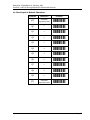
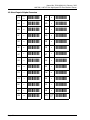
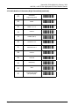
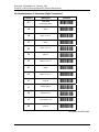
1
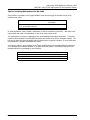
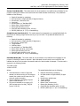
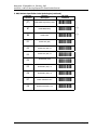
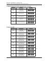
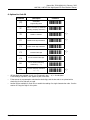
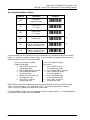
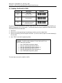
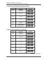
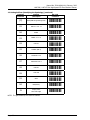
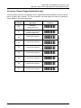
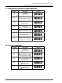
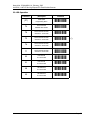
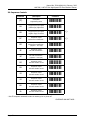
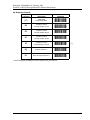
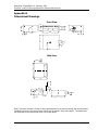
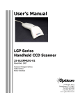
User’s Manual LHA7126, LHA7127 Mini High Speed CCD Fixed Position Scanner Manual No. 25-ULHAR101-01 Rev. February, 2003 8 Olympic Drive Orangeburg, NY 10962 Tel 914.365.0090 Fax 914.365.1251 Contents Section 1 Introduction and Getting Started ..................................... 1 Product Overview ..............................................................................1 Quick Start-Up Procedure ...................................................................1 Section 2 Technical Specifications .................................................... 3 Physical Specifications........................................................................3 Symbologies Supported......................................................................3 Optical Specifications .........................................................................3 Pitch.................................................................................................4 Skew ................................................................................................4 Tilt (Rotation) ...................................................................................4 Curvature .........................................................................................5 Electrical Specifications ......................................................................5 RS232 Communications Specifications .................................................5 Connector Pin-outs ............................................................................6 Environmental Specifications ..............................................................6 Ordering Information .........................................................................6 Section 3 Positioning the Scanner .................................................... 7 Achieving Optimum Performance ........................................................7 Measuring Scanner Performance .........................................................9 The Read Rate Test .........................................................................10 Tips for Achieving High Throughput ..................................................11 Tips for Insuring Highest Data Integrity.............................................11 Tips for Verifying the Presence of a Bar Code.....................................12 Section 4 Configuring the Scanner ................................................. 13 Programming Menus & Commands....................................................13 Default Settings...............................................................................13 Section 5 Application Engineering Support .................................... 15 Technical Assistance and Support .....................................................15 Common Causes of Poor Performance ...............................................15 Modified and/or Customized Scanners ...............................................15 Section 6 Scanner Servicing and Maintenance ............................... 17 Appendix A Programming Menus & Commands ............................. 19 Appendix B Dimensional Drawings ................................................. 57 Appendix C Optical Performance Charts ......................................... 59 Organization of this Manual This manual provides the necessary instructions for installing and using an Opticon LHA7126/LHA7127 Fixed Position Scanner. The manual is organized as follows: Section 1 Introduction and Getting Started Describes the general operation of a LHA7126/LHA7127 scanner. Also provides a Quick Start-Up Procedure that allows you to begin using the scanner immediately. Section 2 Technical Specifications Provides complete specifications, including mechanical details, optical performance, RS232 communications and other technical data. Section 3 Positioning the Scanner for Optimal Performance Provides detailed instructions and tips for mounting and positioning the scanning to obtain the best scanning performance. Application Notes describe guidelines for maximizing specific characteristics. Section 4 Configuring the Scanner Describes how various parameters can be programmed to customize the scanner for your specific application. Section 5 Application Engineering Support Discusses the most common questions and concerns when adapting a LHA7126/LHA7127 scanner in your application. Section 6 Scanner Servicing and Maintenance Discusses the LHA7126/LHA7127 scanner warranty, maintenance and cleaning procedures. Appendices Detailed Supporting Information Provides detailed information in specific areas such as the programming commands for configuring various parameters of a LHA7126/LHA7127 scanner. Manual No. 25-ULHAR101-01, February, 2003 LHA7126 / LHA7127 Mini High Speed CCD Fixed Position Scanner Section 1 Introduction and Getting Started Product Overview LHA7126/LHA7127 Fixed Position Scanners are miniature, 700 scan per second, bar code readers designed to be easily incorporated into host equipment. CCD scanning technology features 100% solid state design with absolutely no moving parts. Durability and reliability are assured. Advanced 32-bit microprocessor technology coupled with Opticon’s proven decoding algorithms result in high speed operation with superior accuracy. The scanners are fully programmable allowing the user to customize parameters including changing communication settings, selecting symbologies, adding prefixes and appending suffixes. Programmable settings can be downloaded from the host CPU or computer directly to the scanner. The LHA7126/LHA7127 scanners are encased in compact, rugged steel enclosures. The compact size permits installation in the tightest areas. Scanners are available in both front and side view configurations allowing great flexibility in mounting and positioning the scanner for optimum performance. Quick Start-Up Procedure This section is for those who wish to start using the scanner before reading the complete manual. In only a few steps the scanner will be operable. Turn off the power to your PC and connect the scanner to an RS232 communications port. Note: You must provide +5 Volt DC power to the scanner. This can be accomplished using the power supply and patch cable available from Opticon. If the power supply is obtained from another source verify that it is identified with the CE mark. Turn on the power to the PC. 1) Using communications software (e.g., Procom), set the communication parameters: 9600 baud, 1 Start/Stop Bit, 8 Data Bits, No Parity, No Handshaking, No Flow Control 2) If you are operating in a Microsoft Windows 3.1 environment, skip to Step 5. 3) If you are operating in a Microsoft Windows 95/98/ 2000/ XP environment, you can set the communication parameters using Hyper Terminal as follows: ♦ Open Hyper Terminal. This can be done from Start→Programs→Accessories/ Communications ♦ Select Hypertrm.exe to create a New Connection ♦ In the Connection Description dialog screen enter a name for the new file. If desired, select an Icon. Click OK ♦ In the Connect To (Phone Number) dialog screen, in the box entitled: Connect using. select the communication port, for example, “Direct to Com 1” Click OK ♦ In the Com 1 Properties screen, enter the appropriate Port Settings: Bits per second = 9600, Data bits = 8, Parity = None, Stop Character = 1, Handshaking = None, Click OK ♦ The hyper-terminal folder you just created will open. From the File pull-down menu, select Properties then click on the Setting Tab Page 1 Manual No. 25-ULHAR101-01, February, 2003 LHA7126 / LHA7127 Mini High Speed CCD Fixed Position Scanner ♦ In the Properties Settings dialog screen, Select Terminal keys for the Function, arrow and control key; then Select ANSI for Emulation; the Back scroll buffer line can remain at the default 500 ♦ Click on the ASCII Setup button. In the ASCII Setup screen, select Echo typed locally so that any keyboard commands you input will appear on your screen. Click OK. This returns you to the Properties Setting. Click OK 4) Your PC and the scanner should now communicate. Skip to Step 6. 5) In a Microsoft Windows 3.1 environment, set the communication parameters using the Terminal function of Windows. a) From Window’s Program Manager Main Menu, select Terminal. ♦ From the Terminal menu, select Settings. ♦ From the Settings menu, select Terminal Emulation. ♦ Set the emulation to TTY (generic). ♦ From the Settings menu, select Terminal Preferences and select the following Terminal Modes: Line Wrap Local Echo Sound CR /LF: Inbound, Outbound Columns: 80 From the Settings menu, select Communications , select the COM port, and set communication parameters as shown in Step 2, including no flow control 6) To verify that the scanner and the PC are communicating properly, send the following command from your PC keyboard to activate the scanner’s buzzer. Send the command: <Escape> V5 <Carriage Return> Note: Be sure to use capital letters, e.g. “V5”, not “v5”. The buzzer should sound, indicating that good communications have been established 7) A red scanning light should be visible. If it is not visible, the scanner may be in a mode that requires a “Trigger” Command from the PC to activate it. You can exit that mode by sending the following command from your PC keyboard: <Escape> S7 <Carriage Return> 8) The “Trigger” mode will now be deactivated and the red scanner light will be continuously illuminated. This Quick Start-Up procedure will get you started. However, to best understand the full capabilities of this scanner, you should read the complete manual. Page 2 Manual No. 25-ULHAR101-01, February, 2003 LHA7126 / LHA7127 Mini High Speed CCD Fixed Position Scanner Section 2 Technical Specifications Physical Specifications Case Material Dimensions (LxHxW) Weight Cable Length Mounting Steel (Black) Side View Front View 52 x 20 x 55 mm 47 x 20 x 55 mm (1.85 x 0.78 x 2.2 in) (1.95 x 0.78 x 2.2 in) 100 g (3.5 ounces) w/o cable 2.8 m (6 ft) with DB25 pin female connector 4 threaded (M-3) mounting holes (2 on each side) (not to extend more than 3 mm into the case) Symbologies Supported ♦ ♦ ♦ ♦ ♦ Codabar (NW-7) Code 39 Code 93 Code 128 Industrial 2 of 5 ♦ ♦ ♦ ♦ Interleaved 2 of 5 MSI / Plessey WPC (UPC / EAN / JAN) IATA Optical Specifications Scan Rate Wavelength of LED Illumination Read Sensor Focal Distance (nominal): Narrow Bar Resolution Minimum PCS 700 scans per second ±10% 660 nanometers CCD linear array Side View Front View 1.2 inches from window 1.4 inches from window 5.0 mil at 0.9 PCS 0.45 (min. background reflectance of 70%) Page 3 Manual No. 25-ULHAR101-01, February, 2003 LHA7126 / LHA7127 Mini High Speed CCD Fixed Position Scanner Pitch Side View 10° 10° 13° 15° OK 30° OK 20° α2 Recommended operation at 10° < α1, α2 < 15°. Avoid specular reflection dead zone (hatched). Skew Front View β Side View β β β β = 0 to 6° β = 0 to 6° (h = 31.4 mm, α2 = 10°, θ = 0°, R = ∞) (h = 35.4 mm, α2 = 10°, θ = 0°, R = ∞) Tilt (Rotation) Side View θ θ BCD θ = 0 to 10° (h = 31.4 mm, α2 = 10°, β = 0°, R = ∞) Front View θ θ BCD (h = 35.4 mm, α2 = 10°, β = 0°, R = ∞) Note: Front View is LHA7127, Side View is LHA7126. Page 4 θ = 0 to 10° α1 10° OK 10° Height of barcode 10° Height of barcode 15° Hatched no read specular zone ±13° 25° α1 OK 30° 20° Hatched no read specular zone ±10° 25° Front View α2 Manual No. 25-ULHAR101-01, February, 2003 LHA7126 / LHA7127 Mini High Speed CCD Fixed Position Scanner Curvature h JAN 13: R = 30 mm (1.2" ) or JAN 8: R= 20 mm (0.8") or Where: PCS 0.9, h = 35.4 α2 = 10°,β = 0°, θ= 0° R Electrical Specifications Operating Voltage Current Operating Static Surge +5VDC + 5% 158 mA typical; 220 mA max. 150 mA max. 3 A max. RS232 Communications Specifications RS232 Data Transmission Format Parameter Timing No. of Start Bits No. of Stop Bits No of Data Bits Parity Baud Rate Handshaking Default Asynchronous 1 bit 1 bit 8 bit None 9600 baud None Optional Settings 1 or 2 bits 7 or 8 bits Odd / Even / None 300 to 38,400 baud Hardware / Software/ None RS232 Transmit / Receive Character Format TXD/ RXD Start Bit LSB 7 or 8 Data Bits MSB Parity Bit Stop Bit RS232 Data Format Transmit Receive Decoded Data ESC Command STX Command CR CR ETX RS232 Signal Level Signal Name TXD RXD In / Out Out In Mark/Off -5 to -15 -3 to -15 Space/On +5 to +15 +3 to +15 Page 5 Manual No. 25-ULHAR101-01, February, 2003 LHA7126 / LHA7127 Mini High Speed CCD Fixed Position Scanner Connector Pin-outs DB25 pin Female connector with screws Pin No. 1 2 3 4 5 7 16 25 Signal Frame Ground RXD TXD CTS RTS Signal Ground Trigger +5V Color Black White Green Blue Gray Purple Brown Red Environmental Specifications Temperature Operating Storage 0° to +40° C (+32 to +104° F) -10° to +60° C (+14 to +140° F) Humidity (non- condensing) Operating 20 to 80% Storage 20 to 90% Ambient Light Fluorescent or incandescent: below 5 kilolux Ordering Information Part No. Model LHA7127RR1S-xxx* Front View LHA7126RR1S-xxx* Side View * Where "xxx" is configuration dependant. Page 6 Direction Input Output Input Output Input - Manual No. 25-ULHAR101-01, February, 2003 LHA7126 / LHA7127 Mini High Speed CCD Fixed Position Scanner Section 3 Positioning the Scanner Achieving Optimum Performance Three items greatly impact performance: 1) Distance (from the scan window) to the bar code 2) Specular Reflection; and 3) Quality of Bar Code Labels 1) Distance to the Bar Code The operation of the scanner is similar to a camera. If you photograph an object that is out of focus, the resulting picture will be blurry. The same is true with the scanner. If the bar code label is out of focus, the scanner may have difficulty decoding what appears to be fuzzy bars and spaces. Focal Distance Ideally, the distance from the window of the scanner to the bar code label should be equal to the focal distance of the scanner. For the LHA7126/LHA7127 fixed position scanners, the nominal focal distances are: Side View (LHA7126) Front View (LHA7127) 1.2 inches (31 mm) 1.4 inches (35 mm) Page 7 Manual No. 25-ULHAR101-01, February, 2003 LHA7126 / LHA7127 Mini High Speed CCD Fixed Position Scanner Depth-of-Field Just as with a camera, the scanner has a depth-of-field. It can read bar codes that are not precisely at the focal distance - maybe a little closer, or a little farther away. However, if the bar code label is positioned too far from the focal distance, the scanner may not be able to successfully decode it. The depth-of-field varies based on the density of the bar code, i.e., the thickness of the bars. Very high density bar codes (which have very narrow bars) are readable over a much shorter distance range than low density bar codes with larger bars. The following table shows the “typical” depth-of-field (closest to farthest reading distances ) for the LHA7126/LHA7127 scanners. The actual performance may differ slightly from unit to unit. Also, it is important to note that this data was measured under ideal conditions using high quality bar code labels. In a “real world” environment the conditions will not be as ideal. Therefore, the best practice is to position the scanner at its focal distance rather than at the extremes of its depth-of-field. Typical Reading Distance from Window (Depth of Field) Density of Bar Code 15 mil 10 mil 6 mil 4 mil Front View Near Far Distance Distance 0.6” 2.3” 0.8” 2.2” 1.1” 1.8” 1.3” 1.65” Side View Near Far Distance Distance 0.3” 2.5” 0.5” 2.0” 0.7" 1.7" 0.9” 1.4” Readable Bar Code Width (Field-of-View) Distance from Window 0.5” 1.0” 1.5” 2.0” 2.5” Front View Max. Width 2.0” 2.7” 3.4” 3.9” 4.5" Side View Max. Width 2.4” 3.1” 3.5” 3.9” 3.2" The table above shows the field-of-view at various distances from the window. The field-of-view is the maximum width that the scanner is capable of reading. A bar code label positioned anywhere within this field-of-view can be decoded. The field-of-view is also a measure of the widest bar code label that can be read. Remember: The width of a bar code label includes not only the bars and spaces but also the required white space (quiet zone) on each end. Good design policy is to position the scanner at its focal distance and at the center of the field-of-view. Do not position it near the extremes of the reading range. Page 8 Manual No. 25-ULHAR101-01, February, 2003 LHA7126 / LHA7127 Mini High Speed CCD Fixed Position Scanner 2) Avoiding Specular Reflection Do not position the scanner at an angle that causes the LED illumination to be reflected directly back into the scanner. This is called specular reflection. Too much reflected light can “blind” the scanner preventing a good decode. If the bar code label is located on a flat surface, specular reflectivity occurs between 0 to 10 degrees off perpendicular. (See diagram) If the bar code label is located on a cylindrical surface, such as a test tube, the angle of specular reflection is measured tangent to the curve. If the curved surface is also moving, there may be more than one position causing specular reflection. The following diagram indicates the area to avoid: Front View Side View Hatched no read specular zone ±10° 13° Hatched no read specular zone ±10° Height of barcode Height of barcode 3) Quality Bar Code Labels The quality of the bar code label can affect the scanning performance. Poor quality labels are more difficult to decode and may result in non-reads or potential misreads. The bar code label should be printed to specifications. This means that the bars are printed within spec, with the correct widths, no ink spread, crisps edges and no voids. There should be a sufficient quiet zone on both end of the bar code label. For best results, the paper or label stock should have a matte finish to diffuse light. The print contrast signal (which is a comparison of the reflectance of the bars and the background stock) should be as high as practical. Measuring Scanner Performance Two methods are helpful in determining the optimum position of the scanner. The first method is to program the scanner for Trigger Disable and Continuous Read modes. The scanner will be always on and will continuously read the same bar code. Since the buzzer sounds each time the bar code is read, the sound of the buzzer can be used like a “Geiger counter”. As the position of the scanner changes the sound of the buzzer will change. The buzzer sound will be loudest and most continuous at the best reading positions. Page 9 Manual No. 25-ULHAR101-01, February, 2003 LHA7126 / LHA7127 Mini High Speed CCD Fixed Position Scanner The Read Rate Test The second method, the Read Rate Test, provides a mathematical calculation of scanning performance. In this test the scanner scans a bar code 700 times and then calculates the number of those scans that resulted in a good decode. That number, expressed as a percentage, will be transmitted to the host. For example, 93% means that the scanner decoded the bar code symbol 93 times out of the 650 scan attempts. By performing the Read Rate Test with the scanner mounted in various positions you can determine which of those locations results in the best performance. How to perform the Read Rate Test Perform the following steps after you have correctly configured communications to the computer via your RS232C port and power is made available to the scanner: Send the command: <Escape> U8 <Carriage Return> Note: Be sure to use capital letters, e.g. “U8”, not “u8”. The scanner will read the barcode continuously and will display the ratio of the number of successful reads to the total number of attempts. The printout on the screen will appear as follows: (Example) 700d OK 93.5% CODE-39 TEST The number in the upper left indicates the number of times the decoder ran while scanning at 700 scans per second. The number can be lower than 700 when reading noisy barcodes. The upper right percentage indicates the ratio of the number of successful reads to the total number of attempts. By positioning the scanner at the optimal distance from the barcode with the correct orientation and with a grade-A quality barcode readings of 95% or higher are expected. Reset the scanner after testing. Page 10 Manual No. 25-ULHAR101-01, February, 2003 LHA7126 / LHA7127 Mini High Speed CCD Fixed Position Scanner Application Notes Tips for Achieving High Throughput In some applications your primary objective may be to achieve the highest possible throughput rate. The following list identifies the parameters and scanner settings that can maximize scanning and decode throughput speed. Note, by emphasizing maximum throughput, other areas of performance may be affected. For example, the number of non-reads could increase. If high throughput is critical, consider some or all of these settings: ♦ Operate in the Trigger Disabled mode. Operation of the trigger can require as much as 200 msec before decoding begins, slowing down throughput rate. ♦ Only enable those symbologies that you will be decoding. ♦ Eliminate all suffixes and prefixes. ♦ Minimize the number of redundant reads required before transmitting data. ♦ Transmit the decoded data at the highest baud rate, 38,400 baud. ♦ Disable buzzer functions. Tips for Insuring Highest Data Integrity There are several parameters that can enhance your confidence that the correct bar code data is transmitted. Note that by emphasizing the accuracy and security of the data other areas of the scanner operation may be affected, for example, you may not achieve the highest throughput. If accuracy and data integrity are critical, consider some or all of these settings: ♦ Program the scanner to require a high number of redundant decodes prior to transmitting. For example, program the scanner to decode a bar code exactly the same way three consecutive times before transmitting the data. Then decoding the bar code the same way 2 out of 3 times or any 3 out of 4 times is not sufficient. It must obtain three consecutive and identical decodes. ♦ Utilize a predetermined, fixed-length of bar code. Program the scanner to only decode a bar code of that length. Bar codes of any other length will be ignored. ♦ The quality of the printed bar code must be excellent. ♦ Use a bar code symbology that contains an internal check digit and program the scanner to calculate that check digit for validity prior to transmitting. ♦ Do not use a symbology with poor internal verification, or subject to partial decodes, such as 2 of 5 or MSI/Plessey. ♦ Only enable those symbologies that you will be decoding. ♦ Transmit data at low baud rates to minimize communication errors. Enable the “Number of Characters Transmitted”. The scanner will calculate and transmit a number indicating the total number of characters it is transmitting. Your host application program can compare this number with the actual number of characters received to verify that the correct amount of data is received. Page 11 Manual No. 25-ULHAR101-01, February, 2003 LHA7126 / LHA7127 Mini High Speed CCD Fixed Position Scanner Tips for Verifying the Presence of a Bar Code If the scanner is operated in the “trigger enabled” mode and the trigger is activated, one of three conditions may occur: A bar code is scanned and decoded. A bar code is scanned but is not decoded (e.g., print quality was poor) No bar code is present Decoded data is transmitted No data is transmitted No data is transmitted In some applications, when no data is transmitted, it may be important to know why. Was there a bar code present that could not be decoded, or was no bar code present at all? This requirement is common in applications such as automated blood analysis equipment. Test tubes containing blood samples from many different people are loaded into a rack for automatic analysis. The bar code on each tube ties that sample and the results back to a specific individual. If no bar code data is transmitted it is critical to understand the reason. Your Opticon scanner, when operated in the Trigger Enabled mode, can be programmed to transmit an error message which indicates whether or not a bar code was present. The following table shows the message that will be transmitted for each condition. Presence/Absence of bar code Bar code was present and correctly decoded No bar code was present Bar code was present but could not be decoded Page 12 Scanner Transmits Decoded Data <STX> “?” <ETX> <STX> “>” <ETX> Manual No. 25-ULHAR101-01, February, 2003 LHA7126 / LHA7127 Mini High Speed CCD Fixed Position Scanner Section 4 Configuring the Scanner Since the operation of a LHA7126/LHA7127 scanner is microprocessor controlled, it is possible to modify or program its operation to match your specific application. Changes in parameter settings can be changed or programmed in two ways. (1) The first method employs specially designed programming bar codes which instruct the scanner to modify specific parameters. (2) The scanner can also be programmed by sending software instructions from the host PC to the scanner via the RS232 connection. Programming Menus & Commands Appendix A contains full instructions on how to configure the scanner as well as a complete listing of the computer commands and programming bar codes that are available to customize the scanner for your application. Default Settings When you modify or change any parameters, the scanner can be programmed to retain the new parameter in memory, even if power is interrupted or terminated. If for any reason, however, the scanner is instructed to “return all parameters to default settings,” it will return to the U4 default %) throughout the menus to settings. Default settings are indicated by a pointing hand symbol ( follow. To restore the “out-of-the-box” settings shown in the following table, use the U4 setting. Parameter “Out-of-the-Box” Setting (U4) 9600 baud 8 data bits RS 232 1 stop bit Communications No parity No handshaking Scan Rate 700 Scans/Second Disabled Trigger Function Scanner Timeout 2 Seconds After Triggering Read Mode Multiple Read Mode Redundant Decodes Read Barcode Twice Bar Code WPC , 2 of 5 , NW-7 , Code 39 Symbologies Code 93 , Code 128, IATA, MSI/Plessey Maximum Volume Buzzer After Decode 3kHz, 2kHz After Decode Duration 200 ms Error Indications No Bad Read Good Read LED After Decode 200 ms Filter Output From Low or High Gain Page 13 Manual No. 25-ULHAR101-01, February, 2003 LHA7126 / LHA7127 Mini High Speed CCD Fixed Position Scanner Section 5 Application Engineering Support Technical Assistance and Support Opticon is eager to help you integrate the LHA7126/LHA7127 scanner into your application. Our technical support staff is available to answer any questions or work with you to adapt the scanner to your specific situation. We are happy to answer your questions, assist in configuring and positioning the scanner for optimum operation, and help resolve any problems you encounter. Call us at 1 (800) 6360090. Common Causes of Poor Performance The most common reasons for poor scanning performance are listed below: ♦ Bar codes are not positioned at the focal distance of the scanner. ♦ Specular reflection is impacting the scanner. Change the angle/position of the scanner or the bar code. ♦ Poor quality of printed bar codes. Bar codes are out of specification. ♦ The paper on which the bar code is printed is highly reflective or has a glossy finish causing light to be reflected into the scanner. ♦ The distance from the scanner to the bar code is not suitable for the density of the bar code. Or the density of the bar code beyond the scanners capability. If the red illuminating light of the scanner is not on, the scanner may be in the “Trigger Enable” mode expecting a trigger signal. Modified and/or Customized Scanners Opticon will work with you to modify or customize scanners to match your requirements. Scanners can be modified in terms of connectors type, pin-outs, cable length, default settings, custom software and many other areas. Opticon will modify scanners in our factory and ship you scanners that match your specific requirements. By incorporating your modifications directly into production scanners, you receive scanners tailored for your need. They can be used immediately without the need for further modification or rework. Page 15 Manual No. 25-ULHAR101-01, February, 2003 LHA7126 / LHA7127 Mini High Speed CCD Fixed Position Scanner Section 6 Scanner Servicing and Maintenance The LHA7126/LHA7127 scanner contains no user adjustable or serviceable parts in the interior of the scanner. All product service must be performed by the Opticon Service Department in Orangeburg, NY. Opening the scanner will void the warranty and could expose the operator to LED light. The LED's are classified as a Class 1 LED Product per IEC 825-1 (1997). CAUTION: Use of controls or adjustments or performance of procedures other than those specified herein may result in hazardous LED light exposure. CAUTION: Class 1 LED power up to 15 mW in a 0.1ms pulse at 635-670 nm could be accessible in the interior. The LHA7126/LHA7127 is warranted for 5 years including parts and workmanship. If you need warranty or out-of-warranty repair, first call 1-800-636-0090 to obtain a Returned Material Authorization (RMA) number. You will be provided a number and shipping instructions. There is no scheduled maintenance required for the LHA7126/LHA7127. The scanner can be cleaned using a water dampened, lint free or lens cloth. Be careful to avoid excessive moisture that would penetrate the housing or obscure the window. While use of cleaning fluids other than water are not recommended, a neutral detergent or ethanol would be preferred if necessary. Do not use bleach at full or diluted strength as damage to the painted case and/or window may result. Page 17 Manual No. 25-ULHAR101-01, February, 2003 LHA7126 / LHA7127 Mini High Speed CCD Fixed Position Scanner Appendix A Programming Menus & Commands Index 1. Global Default & Scanner Configurations........................................20 2. Symbology Selection ....................................................................23 3. Add/Activate Specific Bar Code Symbologies ..................................24 4. Delete/Deactivate Specific Bar Code Symbologies ...........................26 5. Options for UPC...........................................................................27 6. Options for Code 39.....................................................................28 7. Options for Codabar (NW-7) .........................................................29 8. Options for 2 of 5 ........................................................................30 9. Options for IATA..........................................................................31 10. Fixing the Number of Digits ........................................................32 11. Creating a Prefix and/or Suffix ....................................................33 12. Setting Prefixes (Identifying the Symbology) ................................34 13. Setting Suffixes (Identifying the Symbology) ................................35 14. Direct Input of Numeric Characters..............................................37 15. Direct Input of Alpha Characters .................................................38 16. Direct Input of Control Characters ...............................................39 17. Enable Number of Characters/Digits Transmitted ..........................39 18. Disable Number of Characters/Digits Transmitted .........................41 19. Communication Parameters ........................................................42 20. Handshaking .............................................................................44 21. Buzzer Operation .......................................................................45 22. Positive & Negative Bar Codes ....................................................47 23. Setting the Trigger Function .......................................................47 24. Selecting the Read Mode ............................................................48 25. Scanner Timeout (Trigger Enabled Mode only) .............................50 26. Redundant Decoding ..................................................................51 27. Transmitting Error Indications (Trigger Enabled only) ...................52 28. Print Quality Adjustments ...........................................................52 29. LED Operation ...........................................................................53 30. Sequencer Controls ....................................................................54 Page 19 Manual No. 25-ULHAR101-01, February, 2003 LHA7126 / LHA7127 Mini High Speed CCD Fixed Position Scanner 1. Global Default & Scanner Configurations Computer Command Function /Description Bar Code Command (Z7) START/END Programming Menu -[8- 1Y Clear all prefixes -2Z- 1Z Clear all suffixes -2[- P6 Disable Graph Mode -Q7- P9 Enable Graph Mode -Q:- U0 Scanner Test Mode -V1- U3 Straight Across Scan Mode -V!- U4 Return to Default Settings -V5- % U8 Read Rate Mode -V9- U9 Graph Mode (TBD) -V:CONTINUED ON NEXT PAGE… Page 20 Manual No. 25-ULHAR101-01, February, 2003 LHA7126 / LHA7127 Mini High Speed CCD Fixed Position Scanner 1. Global Default & Scanner Configurations (continued) Computer Command Function /Description Bar Code Command (Z7) START/END Programming Menu -[8- Z1 Reset all values set by command -[2- Z2 Save all values set by command (not lost upon power off) -[3- Z3 Display software settings and version number -[!- Z4 Display prefix/suffix value length (expressed in hexadecimal format) -[5- Note: Where computer commands appear in parenthesis, bar code commands must be used to program the scanner. %) symbol throughout the menus to Note: Scanner default settings are indicated by a pointing hand ( follow. * Use Z2 (Save all values set by command) after computer command to store settings in memory prior to power off. U4 Command (U4) - The U4 command resets all parameters for an established set of defaults defined as follows: ♦ ♦ ♦ ♦ ♦ ♦ ♦ ♦ ♦ ♦ ♦ Discriminates the following symbologies: WPC (UPC, EAN, JAN), I 2 of 5, NW-7 (Codabar), Code 39, Code 128, Code 93, MSI/Plessey and IATA. No fixed number of digits defined (32 digits maximum). Normal scan, Multiple read. Low or high analog gain. Small and large. No verification, no "Bad Read (BR)". Buzzer 3KHz and 2KHz, volume maximum Buzzer after decoding (200 ms). Good LED after decoding (green 200 ms). RS232C (9600 bps, 8, 1, np, no handshaking). LED ON – Trigger disabled Page 21 Manual No. 25-ULHAR101-01, February, 2003 LHA7126 / LHA7127 Mini High Speed CCD Fixed Position Scanner Scanner Test Mode (U0) - This mode resets all unit parameters to a predefined set of defaults for the purpose of putting the scanner into a test mode which reads barcodes continuously. The predefined defaults are the following: ♦ ♦ ♦ ♦ ♦ ♦ ♦ ♦ ♦ Reads all barcodes by symbology No fixed number of digits defined (32 digits minimum). Normal scan, continuous scan. Large only. No verification, no "Bad Read (BR)". Buzzer 3KHz, volume maximum. Buzzer after decoding (10 ms). Good LED after decoding (green, 100 ms). RS232C (9600 bps, 8, 1, np, no handshaking). Straight Across Scan Mode (U3) - This mode resets all unit parameters to a predefined defaults for the purpose of allowing straight across scanning of up to 4 labels. The predefined defaults are the following: ♦ ♦ ♦ ♦ ♦ ♦ ♦ ♦ ♦ ♦ Reads all barcodes by symbology. No fixed number of digits defined (32 digits max.) Normal scan, multiple scan. Trigger disable. Small and large. No verification, no "Bad Read (BR)". Buzzer 3KHz and 2KHz, volume max. Buzzer after decoding (200 ms). Good LED after decoding (green, 200 ms). RS232C (9600 bps, 8, 1, np, no handshaking). Read Rate Mode (U8) - This mode resets all unit parameters to a predefined set of defaults for the purpose of checking the scanner read rate. When activated, the test result is sent via RS232C and indicates the ration of the number of successful read to the total number of attempts. The test result is reported in the following format: 700 d OK: 93.5% *CODE-39 TEST* Where: The predefined defaults are the following: ♦ ♦ ♦ ♦ ♦ 700d indicates the number of times the decoder ran while scanning at 700 scans per second (the number can be lower than 700 with poor quality barcodes). 93.5% indicates the percentage of good reads to total attempts. T The control character to be output is CR (0DE carriage return line fed), "ESC[3A" (cursor 3 line UP). Page 22 ♦ ♦ ♦ ♦ ♦ ♦ ♦ Reads all barcodes by symbology. No fixed number of digits defined (32 digits max.). Normal scan, multiple scan. Trigger disabled. Small and large. Buzzer 3 KHz, volume max.) Buzzer after decoding (10 ms). Good LED after decoding (green 100 ms) RS232C (9600 bps, 8, 1, np, no handshaking). Manual No. 25-ULHAR101-01, February, 2003 LHA7126 / LHA7127 Mini High Speed CCD Fixed Position Scanner 2. Symbology Selection Computer Command Function /Description Bar Code Command (Z7) START/END Programming Menu -[8- A0 Enable all bar code symbologies -B1- % A1 Only WPC (including Addon) -B2- A2 Only Code 39 -B3- A3 Only Codabar (NW-7) -B!- A4 Only 2 of 5 (Industrial or Interleaved) -B5- A5 Only Code 93 -B6- A6 Only Code 128 -B7- A7 Only MSI/Plessey -B8- A8 Only IATA -B9- J1 Only UPC (A/E) -K2- J2 Only UPC (A/E)+2 -K3- J3 Only UPC (A/E)+5 -K!- J4 Only EAN -K5- J5 Only EAN +2 -K6CONTINUED ON NEXT PAGE… Page 23 Manual No. 25-ULHAR101-01, February, 2003 LHA7126 / LHA7127 Mini High Speed CCD Fixed Position Scanner 2. Symbology Selection (continued) Computer Command Function /Description Bar Code Command (Z7) START/END Programming Menu -[8- J6 Only EAN +5 -K7- J7 Only Industrial 2 of 5 -K8- J8 Only Interleaved 2 of 5 -K9- Z9 Remote Menu -[:- 3. Add/Activate Specific Bar Code Symbologies Computer Command Function /Description Bar Code Command (Z7) START/END Programming Menu -[8- B1 Enable all WPC (including Addon) B2 Enable Code 39 B3 Enable Codabar (NW-7) B4 Enable 2 of 5 (Industrial/Interleaved) B5 Enable Code 93 (Factory Set) B6 Enable Code 128 (Factory Set) -C2- % -C3- % -C!- % -C5- % -C6- % -C7- % CONTINUED ON NEXT PAGE… Page 24 Manual No. 25-ULHAR101-01, February, 2003 LHA7126 / LHA7127 Mini High Speed CCD Fixed Position Scanner 3. Add/Activate Specific Bar Code Symbologies (continued) Computer Command Function /Description Bar Code Command (Z7) START/END Programming Menu -[8- B7 Enable MSI/Plessey B8 Enable IATA R1 Enable UPC (A/E) -S2- R2 Enable UPC (A/E) +2 -S3- R3 Enable UPC (A/E) +5 -S!- R4 Enable EAN (13/8) -S5- R5 Enable EAN (13/8) +2 -S6- R6 Enable EAN (13/8) +5 -S7- R7 Enable Industrial 2 of 5 -S8- R8 Enable Interleaved 2 of 5 -S9- -C8- % -C9- % Page 25 Manual No. 25-ULHAR101-01, February, 2003 LHA7126 / LHA7127 Mini High Speed CCD Fixed Position Scanner 4. Delete/Deactivate Specific Bar Code Symbologies Computer Command Function /Description Bar Code Command (Z7) START/END Programming Menu -[8- 4A Disable all WPC (including Addon) -5B- 4B Disable UPC (A/E) -5C- 4C Disable UPC (A/E) +2 -5D- 4D Disable UPC (A/E) +5 -5E- 4E Disable EAN (13/8) -5F- 4F Disable EAN (13/8) +2 -5G- 4G Disable EAN (13/8) +5 -5H- 4H Disable Code 39 -5I- 4I Disable Codabar (NW-7) -5J- 4J Disable 2 of 5 (Industrial/Interleaved) -5K- 4K Disable Industrial 2 of 5 -5L- 4L Disable Interleaved 2 of 5 -5M- 4M Disable Code 93 -5NCONTINUED ON NEXT PAGE… Page 26 Manual No. 25-ULHAR101-01, February, 2003 LHA7126 / LHA7127 Mini High Speed CCD Fixed Position Scanner 4. Delete/Deactivate Specific Bar Code Symbologies (continued) Computer Command Function /Description Bar Code Command (Z7) START/END Programming Menu -[8- 4N Disable Code 128 -5O- 4O Disable MSI/Plessey -5P- 4P Disable IATA -5Q- 4Z Disable all symbologies -5[- Computer Command Function /Description Bar Code Command (Z7) START/END Programming Menu -[8- E2 UPC-A (13 Digits) Add leading zero; Enable check digit E3 UPC-A (12 Digits) Do not add leading zero; Enable check digit -F!- E4 UPC-A (12 Digits) Add leading zero; Disable check digit -F5- E5 UPC-A (11 Digits) Do not add leading zero; Disable check digit -F6- E6 UPC-E (8 Digits) Add leading zero; Enable check digit -F7- E7 UPC-E (7 Digits) Do not add leading zero; Enable check digit E8 UPC-E (7 Digits) Add leading zero; Disable check digit -F9- E9 UPC-A (6 Digits) Do not add leading zero; Disable check digit -F:- 5. Options for UPC -F3- % -F8- % Page 27 Manual No. 25-ULHAR101-01, February, 2003 LHA7126 / LHA7127 Mini High Speed CCD Fixed Position Scanner 6. Options for Code 39 Computer Command Function /Description Bar Code Command (Z7) START/END Programming Menu -[8- 7C Enable 1 character (3 characters including start/stop characters) -8D- 7D Disable 1 character C0 Disable check digit calculation C1 Enable check digit calculation C2 Transmit check digit C3 Do not transmit check digit -D!- D0 Do not transmit start/stop characters (*……*) -E1- D1 Transmit start/stop characters (*……*) -8E- % -D1- % -D2-D3- % -E2- % • 43 Data digits are available: 0 to 9, A to Z (caps only) plus . - $ / + % and space. If a check digit is present, it will appear as part of the data. • If the scanner is programmed to calculate the check digit, and the bar code is not printed with a check digit, the bar code will not read. • Another option available for Code 39 is to enable the reading of a single character bar code. See the section on Fixing the Digit for this option. Page 28 Manual No. 25-ULHAR101-01, February, 2003 LHA7126 / LHA7127 Mini High Speed CCD Fixed Position Scanner 7. Options for Codabar (NW-7) Computer Command Function /Description Bar Code Command (Z7) START/END Programming Menu -[8- 7K Enable 1 character (3 characters including start/stop characters) -8L- 7L Disable 1 character F0 Do not transmit start/stop characters -G1- F1 Transmit start/stop characters as ABCD/TN*E -G2- F2 Transmit start/stop characters as abcd/tn*e -G3- F3 Transmit start/stop characters as ABCD/ABCD -G!- F4 Transmit start/stop characters as abcd/abcd F5 Transmit check digit F6 Do not transmit check digit -G7- F7 Do not calculate check digit -G8- % F8 Calculate check digit (Modulo 10) -G9- F9 Calculate check digit (Modulo 16) (AIM specifications) -G:- FB Calculate check digit (Modulo 7) -GC- -8M- % -G5- % -G6- % CONTINUED ON NEXT PAGE… Page 29 Manual No. 25-ULHAR101-01, February, 2003 LHA7126 / LHA7127 Mini High Speed CCD Fixed Position Scanner Codabar (NW-7) Format Start Character 1 to 42 data digits Check digit Stop Character A.... a.... A.... a.... ....T ....t ....A ....a • Codabar (NW-7) has four different start/stop character schemes as shown above. The check digit is optional and, if present, would be the last character. • If the scanner is programmed to calculate the check digit and the bar code is not printed with a check digit, the bar code will not be read. 8. Options for 2 of 5 Computer Command Function /Description Bar Code Command (Z7) START/END Programming Menu -[8- G0 Do not calculate check digit G1 Calculate check digit -H2- G2 Transmit Check digit -H3- % G3 Do not transmit check digit -H!- 7M Enable 2 characters -8N- 7N Disable 2 characters -8O- % -H1- % 2 of 5 Format (Standard and Interleaved) 1 to 44 data digits numeric only (0 to 9) CD Check Digit Opticon strongly recommends that the “Fixing the Number of Digits” featured on page 32 be employed whenever 2 of 5 bar codes are used. Page 30 Manual No. 25-ULHAR101-01, February, 2003 LHA7126 / LHA7127 Mini High Speed CCD Fixed Position Scanner 9. Options for IATA Computer Command Function /Description Bar Code Command (Z7) START/END Programming Menu -[8- D2 Do not calculate check digit D3 Calculate check digit (CPN + Form + Serial) -E!- D4 Calculate check digit (Form + Serial) -E5- D5 Calculate check digit (All data) -E6- D6 Transmit check digit -E7- % D7 Do not transmit check digit -E3- % -E8- The IATA code is a variable length symbology with an optional check digit and non-printable start/stop characters. The following characters are supported: Digits 0 up to 9. The checksum is calculated as the modulo seven of the data string. IATA is an acronym for International Air Transport Association. String format Meaning of Acronym Number of digits (15 total) ♦ ♦ ♦ CPN Coupon 1 AC Airline Code 3 FC Form Code 2 SN Serial Number 8 CD Check Digit 1 Enable check digit check Selection of the check digit calculation Disable transmission of the check digit Check digit calculation: If the check digit calculation is required, then the appropriate calculation method must be selected. Page 31 Manual No. 25-ULHAR101-01, February, 2003 LHA7126 / LHA7127 Mini High Speed CCD Fixed Position Scanner 10. Fixing the Number of Digits Computer Command Function /Description Bar Code Command (Z7) START/END Programming Menu -[8- 7V Enable fixation (1st Length) -I2- 7W Enable fixation (2nd Length) -I5- (H0) Disable fixation H2 Disable 1 character Code 39 and Codabar (NW-7); Disable 2 characters 2 of 5 -I1- % -I3- % H3 Enable 1 character Code 39 and Codabar (NW-7); Enable 2 characters 2 of 5 -I!- To avoid truncation errors, the scanner can be programmed to only decode bar codes of one specific length, i.e., containing a specific number of digits. It is also possible to program the scanner to only decode bar codes of either of two specific lengths. To fix one (1) length (or number of digits) of bar code: 1. Scan “START” to enter the programming mode 2. Scan “Enable fixation” bar code 3. Scan a sample bar code of the desired length 4. Repeat Step #3, re-scanning the sample bar code 5. Scan “STOP” to exit the programming mode To fix two (2) different lengths of bar codes: 1. Scan “START” to enter the programming mode 2. Scan “Enable fixation” bar code 3. Scan a sample bar code of the desired length #1 4. Scan a sample bar code of the desired length #2 5. Scan “STOP” to exit the programming mode NOTE: Fixation can also be programmed using computer commands through your RS232 by typing <ESC>7V<CR> followed by <+>2 digit length 1<CR>. 7W would be appropriate for length 2. Type<+>00<CR> to define either length as no fixed number. “Fixing the Number of Digits” can only be applied to Code 39, Codabar (NW-7), 2 or 5 and MSI/Plessey. PC, Code 93, IATA and Code 128 are not affected. Page 32 Manual No. 25-ULHAR101-01, February, 2003 LHA7126 / LHA7127 Mini High Speed CCD Fixed Position Scanner 11. Creating a Prefix and/or Suffix Computer Command Function /Description Bar Code Command (Z7) START/END Programming Menu -[8- 1Y Clear all Prefixes -2Z- Z4 Display Prefix/Suffix value and length (expressed in hexidecimal format) -[5- The scanner can be programmed to transmit a prefix and/or suffix with the decoded data. A Prefix (or a Suffix) is composed of up to 4 characters. The following steps are used to establish a Prefix that will be transmitted with the bar code data: 1. Scan Start 2. Scan the bar code representing the symbology to which you wish to add a Prefix 3. Scan the character(s) that will comprise the Prefix. Up to four numeric, alpha or control character(s) may be used. 4. Scan “STOP” to exit the Programming Mode. Example: To add the alpha character “A” as a Prefix and “B” as a Suffix to UPC-A bar code data: 1. 2. 3. 4. 5. 6. Scan Scan Scan Scan Scan Scan “START/END Programming Mode” N1, representing a Prefix for UPC-A 0A, representing the alpha character “A” N6, representing a Suffix for UPC-A 0B, representing the alpha character “B” “START/END Programming Mode” The same steps are used to establish a Suffix. Page 33 Manual No. 25-ULHAR101-01, February, 2003 LHA7126 / LHA7127 Mini High Speed CCD Fixed Position Scanner 12. Setting Prefixes (Identifying the Symbology) Computer Command Function /Description Bar Code Command (Z7) START/END Programming Menu -[8- 1Y Clear all Prefixes -2Z- N1 UPC-A -O2- M0 UPC-A +2 or +5 -N1- N2 UPC-E -O3- M1 UPC-E +2 or +5 -N2- N3 EAN-13 -O!- M2 EAN –13 +2 or +5 -N3- N4 EAN-8 -O5- M3 EAN-8 +2 or +5 -N!- M4 Code 39 -N5- M5 Codabar (NW-7) -N6- M6 Industrial 2 of 5 -N7- M7 Interleaved 2 of 5 -N8CONTINUED ON NEXT PAGE... Page 34 Manual No. 25-ULHAR101-01, February, 2003 LHA7126 / LHA7127 Mini High Speed CCD Fixed Position Scanner 12. Setting Prefixes (Identifying the Symbology) (continued) Computer Command Function /Description Bar Code Command (Z7) START/END Programming Menu -[8- M8 Code 93 -N9- M9 Code 128 -N:- D8 IATA -E9- N0 MSI/Plessey -O1- Z4 Display Prefix/Suffix value and length (expressed in hexidecimal format) -[5- 13. Setting Suffixes (Identifying the Symbology) Computer Command Function /Description Bar Code Command (Z7) START/END Programming Menu -[8- 1Z Clear all Suffixes -2[- N6 UPC-A -O7- O0 UPC-A +2 or +5 -P1- N7 UPC-E -O8- O1 UPC-E +2 or +5 -P2- N8 EAN-13 -O9COINTINUED ON NEXT PAGE... Page 35 Manual No. 25-ULHAR101-01, February, 2003 LHA7126 / LHA7127 Mini High Speed CCD Fixed Position Scanner 13. Setting Suffixes (Identifying the Symbology) (continued) Computer Command Function /Description Bar Code Command (Z7) START/END Programming Menu -[8- O2 EAN–13 +2 or +5 -P3- N9 EAN-8 -O:- O3 EAN-8 +2 or +5 -P!- O4 Code 39 -P5- O5 Codabar (NW-7) -P6- O6 Industrial 2 of 5 -P7- O7 Interleaved 2 of 5 -P8- O8 Code 93 -P9- O9 Code 128 -P:- D9 IATA -E:- N5 MSI/Plessey -O6- Z4 Display Suffix value and length -[5- NOTE: The global default, also clears all suffixes. Page 36 Manual No. 25-ULHAR101-01, February, 2003 LHA7126 / LHA7127 Mini High Speed CCD Fixed Position Scanner 14. Direct Input of Numeric Characters Computer Command Function /Description Bar Code Command (Z7) START/END Programming Menu -[8- Q0 0 -R1- Q1 1 -R2- Q2 2 -R3- Q3 3 -R!- Q4 4 -R5- Q5 5 -R6- Q6 6 -R7- Q7 7 -R8- Q8 8 -R9- Q9 9 -R:- (Z7) START/END Programming Menu -[8- Page 37 Manual No. 25-ULHAR101-01, February, 2003 LHA7126 / LHA7127 Mini High Speed CCD Fixed Position Scanner 15. Direct Input of Alpha Characters Page 38 -[8- 0N N -1O- A -1B- 0O O -1P- 0B B -1C- 0P P -1Q- 0C C -1D- 0Q Q -1R- 0D D -1E- 0R R -1S- 0E E -1F- 0S S -1T- 0F F -1G- 0T T -1U- 0G G -1H- 0U U -1V- 0H H -1I- 0V V -1W- 0I I -1J- 0W W -1X- 0J J -1K- 0X X -1Y- 0K K -1L- 0Y Y -1Z- 0L L -1M- 0Z Z -1[- 0M M -1N- (Z7) START/END Program Menu (Z7) START/END Program Menu 0A -[8- Manual No. 25-ULHAR101-01, February, 2003 LHA7126 / LHA7127 Mini High Speed CCD Fixed Position Scanner 16. Direct Input of Control Characters Computer Command Function /Description Bar Code Command (Z7) START/END Programming Menu -[8- 1A STX -2B- 1B ETX -2C- 1C CR -2D- 1D LF -2E- 17. Enable Number of Characters/Digits Transmitted This feature instructs the scanner to calculate and transmit a number indicating the total number of characters that are being transmitted to the host. This feature allows the host to verify that the correct amount of data was received. Computer Command Function /Description Bar Code Command (Z7) START/END Programming Menu -[8- 3A UPC-A -!B- 3B UPC-A +2 or +5 -!C- 3C UPC-E -!D- 3D UPC-E +2 or +5 -!E- 3E EAN-13 -!F- 3F EAN-13 +2 or +5 -!GCONTINUED ON NEXT PAGE... Page 39 Manual No. 25-ULHAR101-01, February, 2003 LHA7126 / LHA7127 Mini High Speed CCD Fixed Position Scanner 17. Enable Number of Characters/Digits Transmitted (continued) Page 40 (Z7) START/END Programming Menu -[8- 3G EAN-8 -!H- 3H EAN-8 +2 or +5 -!I- 3I Code 39 -!J- 3J Codabar (NW-7) -!K- 3K Industrial 2 of 5 -!L- 3L Interleaved 2 of 5 -!M- 3M Code 93 -!N- 3N Code 128 -!O- 3O MSI/Plessey -!P- 3P IATA -!Q- 3Z Transmit data length (all symbologies) -