1
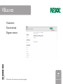
VBus.net
Visualisation
Data download
11202371
*11202371*
Diagram creation
en
Manual
© All contents of this document are protected by copyright.
www.resol.com
en
Contents
1
1VBus.net...................................................... 2
2 Menu functions........................................... 3
3Status........................................................... 3
4Filters........................................................... 4
5 Scheme images........................................... 5
6 Live data view............................................. 6
7 Positioning the data points........................ 7
8 Diagram creation....................................... 8
8.1 Quick diagram............................................................8
8.2 Stored diagrams.........................................................8
9 Diagram functions...................................... 9
9.1Zoom...........................................................................9
9.2Print..............................................................................9
9.3Export..........................................................................9
10Download.................................................. 10
10.1 Quick download......................................................10
10.2 Stored downloads...................................................10
VBus.net is a service portal that offers the possibility
to access solar thermal system data, without any configuration effort, from all over the world.Thus, no DSL
router configuration is required.
To use the VBus.net service, the system must be
equipped with a RESOL DL2 or RESOL DL3 Datalogger. After signing on at http://www.vbus.net, the Datalogger can be registered with the system.
Subject to technical change. Errors excepted.
© 20130110_11202371_VBus.net.monen.indd
2
VBus.net
VBus.net enables users to access their solar thermal
system data from all over the world, just by using a
regular Web browser.
No additional software or app is required, only a
registered account for the VBus.net service, a Web
browser and an Internet connection. Of course, many
mobile devices are supported as well.
2
Menu functions
en
After logging in, different menu items are available on
VBus.net. The menu item Visualization offers access
to the visualisation and download functions of VBus.net.
3
Status
In the Status menu, information about the user account is indicated.
3
4
Filters
en
Filters are used for reducing and customising the
number of data points.
By reducing the number of data points, evaluation and
visualisation can be focussed on certain measuring
and balance values. This helps to keep diagrams concise and to accelerate downloads.
In order to create a filter, proceed as follows:
ÎÎ Select the desired system.
ÎÎ Enter a name for the filter.
ÎÎ Click on the device from which measuring values
are to be added (see arrow).
A selection menu with all data points available opens.
The data points can be selected and unselected individually.
The standard names for the data points can be
changed individually, and a colour can be selected for
the line representing the data point in a diagram.
In order to re-name the data points, proceed as follows:
ÎÎ Enter the desired name in the corresponding
fields of the centre column.
In order to select a colour for the diagram line, proceed as follows:
ÎÎ Click on the coloured box to the right of the desired value.
A colour selection window opens.
ÎÎ Select the desired colour.
In order to save all adjustment changes, proceed as
follows:
ÎÎ Click on the Save button.
4
5
Scheme images
en
In order to create a live data view, a scheme image of
the system can be used.
A selection of standard images is available on VBus.net.
If no fitting image of the desired system is available, a
customised image can be uploaded and used.
Customised images must be .JPG or .PNG format.
In order to use a standard image, proceed as follows:
ÎÎ Select the desired image.
ÎÎ Enter a name for the image.
ÎÎ Click on the desired thumbnail.
ÎÎ Click on the Save button.
To facilitate the selection, the number of images can
be filtered. To do so, proceed as follows:
ÎÎ Select the desired number of collectors and
stores (see Stores and Collectors).
Only the matching images will be displayed.
In order to use a customised image, proceed as follows:
ÎÎ Under Upload new image, click on Select file.
ÎÎ Select the desired .JPG or .PNG file.
ÎÎ Click on the Upload button.
The file will then be transferred to the server.
5
6
Live data view
en
The current measuring values of the solar system can
also be displayed in a scheme image of the system.
By using the Public function, the live data view can
also be displayed externally, e. g. on a website.
In order to create a live data view, a filter (see page
4) and a scheme image (see page 5) have to be
selected or created first! A scheme image is required
as a background for the live data view.
In order to edit a live data view, proceed as follows:
ÎÎ Select the desired system.
ÎÎ Enter a name for the live data view.
ÎÎ Select the desired image.
ÎÎ Select a filter for the data stored.
ÎÎ If publication is to be enabled for the live data
view, tick the Public checkbox.
The corresponding URL will be displayed on the overview page. Thus, a live data view can e. g. be integrated
into a website.To see a live data view integrated into a
website, no login on VBus.net is required.
ÎÎ Click on the Save button.
Now the data points can be positioned on the scheme
image (see page 7).
6
7
Positioning the data points
en
In order to position the data points on the scheme
image, proceed as follows:
ÎÎ In the Edit Scheme menu (see page 4), click
on the Set data field positions button.
The positioning menu opens.
On the left-hand side of the screen, all data points
chosen for the filter selected are listed. For each data
point, the positionable elements are displayed: The
corresponding device, the measuring or balance value
as well as its name.
In order to position elements, proceed as follows:
ÎÎ Select the desired element by clicking and holding
the mouse button.
ÎÎ Drag the element to the desired position.
ÎÎ Release the mouse button.
As soon as the mouse button is released, the position
of the element will be stored automatically.
If the mouse button is released outside the valid image area (the frame around the scheme image), the
element will be set back to its initial position automatically.
In order to remove elements from the scheme image,
proceed as follows:
ÎÎ Select the desired element by clicking and holding
the mouse button.
ÎÎ Drag the element to a position outside the
scheme image.
ÎÎ Release the mouse button.
As soon as the mouse button is released, the position
of the element will be stored automatically.
When the cursor is moved over a data point, all corresponding elements are highlighted in yellow. This
way, the data point can be clearly matched.
After positioning, the live data view can be opened in
a separate window.
7
8
Diagram creation
To chart the data progress over a certain time frame,
customised diagrams of measuring and balance values can be created. For a one-time diagram view, the
Quick-Diagram function is available. If a specific diagram is to be used recurrently, the specifications can
be stored for that purpose.
By using the Public function, diagrams can also be displayed externally, e. g. on a website.
In order to create a diagram, a filter (see page 8)
must be created first!
8.1
Quick diagram
en
In order to create a quick diagram, proceed as follows:
ÎÎ Select the desired system.
ÎÎ Select the desired time frame.
ÎÎ Select the corresponding filter under Stored values.
ÎÎ Click on the Show button.
The data will then be processed automatically. After
that, the diagram is displayed.
8.2
Stored diagrams
In order to store a diagram, proceed as follows:
ÎÎ Select the desired system.
ÎÎ Select the desired time frame.
ÎÎ Select the corresponding filter under Stored values.
ÎÎ If publication is to be enabled for the diagram, tick
the Public checkbox.
The corresponding URL will be displayed on the overview page. Thus, a diagram can e. g. be integrated into
a website. To see a diagram integrated into a website,
no login on VBus.net is required.
8
9
Diagram functions
For stored diagrams, the following diagram functions
can be used.
9.1
Zoom
The Zoom function can be used for viewing a certain
area of the diagram more closely.
ÎÎ In order to zoom in on a part of the diagram,
mark the desired time frame with the mouse.
The marked area is then enlarged automatically.
ÎÎ In order to get back to the previous diagram,
click on Reset zoom.
9.2
Print
9.3
en
The Print function can be used for printing the diagram.
ÎÎ In order to print the diagram, click on the printer
(upper right-hand side).
icon Export
The Export function can be used for storing the diagram as a .PNG or .JPG image, as a .PDF file or as
an .SVG graphic.
ÎÎ In order to export the diagram, click on the ex(upper right-hand side).
port icon ÎÎ Select the desired file format.
The download will start automatically.
9
10 Download
The data logged for a defined time frame can be downloaded in different file formats for evaluation and processing. For a one-time download, the Quick-download function is available. If a specific download is to
be used recurrently, the specifications can be stored
for that purpose.
10.1 Quick download
en
For a Quick download, proceed as follows:
ÎÎ Select a system, a file format and the desired time
frame.
ÎÎ Under Stored data, select whether all data
logged or a filter created previously (see page
4) are to be downloaded.
ÎÎ Click on the Download button.
The download starts.
10.2 Stored downloads
In order to store a specific download for recurrent
use, proceed as follows:
ÎÎ Click on Add new download.
ÎÎ Select a system, a file format and the desired time
frame.
ÎÎ Click on the Save button.
Stored downloads are available in the Downloads
section. There, previously made adjustments can be
changed or downloads can be deleted.
10
en
Notes
11
Distributed by:
RESOL – Elektronische Regelungen GmbH
Heiskampstraße 10
45527 Hattingen / Germany
Tel.: +49 (0) 23 24 / 96 48 - 0
Fax: +49 (0) 23 24 / 96 48 - 755
www.resol.com
[email protected]
Important note
The texts and drawings in this manual are correct to the best of our knowledge. As
faults can never be excluded, please note:
We do not offer a guarantee for the completeness of the drawings and texts of this
manual - they only represent some examples. They can only be used at your own
risk. No liability is assumed for incorrect, incomplete or false information and / or
the resulting damages.
Disclaimer
All measures to ensure the faultless function of the software have been taken. The
manufacturer does not warrant for the software functionality and does not assume
any liability for damage that may have been caused by using the software. This includes especially, but is not limited to: Hardware failure, data loss, financial penalties.
Note
The design and the specifications can be changed without notice.
The illustrations may differ from the original product.
Imprint
This manual including all parts is copyrighted.Another use outside the copyright requires the approval of RESOL – Elektronische Regelungen GmbH. This especially
applies for copies, translations, micro films and the storage into electronic systems.
Editor: RESOL – Elektronische Regelungen GmbH