1
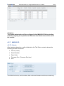
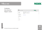
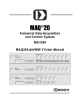
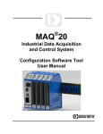
technikmedia User Manual M.A.L PlugIn Dataforth MAQ20 V01.01.01.0002 technikmedia Ingenieurbüro für technische Medien Dipl.-Ing. Dietmar Neumann Am Homberg 13 B D-45529 Hattingen Tel.: +49 2324 34 44 792 Fax: +49 2324 34 44 793 Email: [email protected] Internet: www.technikmedia.de technikmedia User Manual M.A.L. PlugIn Dataforth V01.01.01.0002 2/21 Content 1. General Information ............................................................................................. 4 1.1. Version ......................................................................................................... 4 1.1.1. User Manual IPEmotion PlugIn Dataforth MAQ .................................... 4 1.1.2. IPEmotion PlugIn Dataforth MAQ .......................................................... 4 1.2. IPEmotion ..................................................................................................... 4 2. Introduction .......................................................................................................... 4 3. Setting Up And Removing ................................................................................... 5 3.1. 4. System Requirements .................................................................................. 5 3.1.1. Hardware............................................................................................... 5 3.1.2. Platforms ............................................................................................... 5 3.2. Installation .................................................................................................... 5 3.3. Uninstall ....................................................................................................... 6 Working With IPEmotion Dataforth Plug In .......................................................... 6 4.1. Adding a MAQ20 system to IPEmotion ........................................................ 7 4.1.1. Hardware detection ............................................................................... 7 4.1.2. Manually Adding MAQ 20 System......................................................... 8 4.2. Module Configuration ................................................................................... 9 4.2.1. MAQ20-COM2 ...................................................................................... 9 4.2.1.1. Connection ..................................................................................... 9 4.2.1.2. Real Time Clock (RTC) ................................................................ 10 4.2.1.3. Device .......................................................................................... 10 4.2.2. MAQ20-COM4 .................................................................................... 11 4.2.2.1. Connection ................................................................................... 11 4.2.2.2. Real Time Clock (RTC) ................................................................ 12 4.2.2.3. Device .......................................................................................... 12 4.2.3. MAQ20-DIOL ...................................................................................... 13 4.2.3.1. Device .......................................................................................... 13 4.2.3.2. Input channel ............................................................................... 13 4.2.3.3. Output channel ............................................................................. 13 4.2.4. MAQ20-JTC, MAQ20-KTC, MAQ20-RSTC, MAQ20-TTC................... 14 4.2.4.1. Device .......................................................................................... 14 4.2.4.2. Channels ...................................................................................... 15 4.2.5. MAQ20-IDN, MAQ20-ISN, MAQ20-MVDN, MAQ20-VDN, MAQ20-VSN 16 technikmedia 3/21 4.2.5.1. Device .......................................................................................... 16 4.2.5.2. Channels ...................................................................................... 16 4.2.6. MAQ20-IO ........................................................................................... 18 4.2.6.1. Device .......................................................................................... 18 4.2.6.2. Channel........................................................................................ 18 4.2.7. MAQ20-VO.......................................................................................... 19 4.2.7.1. Device .......................................................................................... 19 4.2.7.2. Channel........................................................................................ 20 4.2.8. 4.3. User Manual M.A.L. PlugIn Dataforth V01.01.01.0002 MAQ20-RTD31 ................................................................................... 20 4.2.8.1. Device .......................................................................................... 20 4.2.8.2. Channel........................................................................................ 21 Using IPEmotion Dataforth Edition ............................................................. 21 technikmedia 1. User Manual M.A.L. PlugIn Dataforth V01.01.01.0002 4/21 General Information This manual describes the structure of the PlugIn and how to use the features for configuring devices of the Dataforth MAQ20 system, taking acquisitions and managing and analyzing the result data. Please read this manual carefully to get to know the operating and to learn more about the functions and special features. This manual also contains information for installing and removing the software. 1.1. Version 1.1.1. User Manual IPEmotion PlugIn Dataforth MAQ This manual has the version 01.03. 1.1.2. IPEmotion PlugIn Dataforth MAQ The description in this documentation refers to the current release with the version number 01.01.01.0003. 1.2. IPEmotion The description in this documentation refers to the current release with the version number 2014 R1.4. 2. Introduction The Dataforth plug in offers you the ability to use the Dataforth MAQ®20 modular data acquisition system. Actually the following modules are supported: - MAQ20-COM2 Communication Module; Ethernet, USB, RS-232 - MAQ20-COM4 Communication Module; Ethernet, USB, RS-485 - MAQ20-DIOL Digital Input/Output Module; 3 to 60VDC, 5-ch Input, 5-ch Output - MAQ20-IDN Analog Input Module; mA, Differential, 8-ch - MAQ20-IO Analog Output Module; mA, ch-ch Isolated, 8-ch - MAQ20-ISN Analog Input Module; mA, Single Ended, 8-ch - MAQ20-JTC Analog Input Module; Type J Thermocouple, 8-ch - MAQ20-KTC Analog Input Module; Type K Thermocouple, 8-ch - MAQ20-MVDN Analog Input Module; mV, 8-ch, Differential - MAQ20-RSTC Analog Input Module; Type R and S Thermocouple, 8-ch - MAQ20-VDN Analog Input Module; V, 8-ch, Differential - MAQ20-VSN Analog Input Module; V, 8-ch, Single Ended - MAQ20-VO Analog Output Module; Voltage, ch-ch Isolated, 8-ch technikmedia - MAQ20-TTC User Manual M.A.L. PlugIn Dataforth V01.01.01.0002 5/21 Analog Input Module; Type T Thermocouple, 8-ch 3. Setting Up And Removing 3.1. System Requirements The minimum hardware and platform requirements fort the application of the IPEmotion Dataforth plug in are outlined below. 3.1.1. Hardware The minimum hardware requirements correspond to those of IPEmotion. 3.1.2. Platforms The IPEmotion Dataforth plug in can be run under the following operating systems: - Windows XP (32 Bit) - Windows Vista (32 Bit) - Windows 7 (32 Bit) 3.2. Installation The following chapter guides you through the installation process of the Dataforth plug in. IPEmotion Dataforth plug in needs administrator rights during installation. For working with the plug in you need at least limited user’s or default user’s rights (Vista). The installation of IPEmotion Dataforth plug in is based on an installationwizard that guides you through the setup process step by step. To install the IPEmotion Dataforth plug in: 1. Double-click the IPEmotion Dataforth PlugIn Vxxx Setup.exe to start the installation wizard. 2. Welcome screen: This is the first screen in the IPEmotion Dataforth plug in installation wizard. Click Next to continue. 3. Installation folder: Accept the default installation location for IPEmotion Dataforth plug in. To select another location click Browse… and select another folder. To get information about available disk space click Disc Cost… By default the plug in is available for anyone. If you want to use if for yourself technikmedia User Manual M.A.L. PlugIn Dataforth V01.01.01.0002 6/21 select Just me. Click Next to continue. 4. Confirm installation: This screen indicates that IPEmotion Dataforth plug in is ready to install. Click Next to start installation. 5. Installation: A progress bar is shown during the installation process. 6. Installation complete: After successful installation this screen is shown. Click Close to finish installation. 3.3. Uninstall Windows XP/Vista: 1. Click on Start button, click on Settings and then on Control Panel, click on Add or Remove Programs 2. Select the IPEmotion Dataforth plug in, and then click Remove to start the installation wizard. 3. Click Yes to confirm removal. Windows 7: 1. Open Programs and Features by clicking the Start button , clicking Control Panel, clicking Programs and the clicking Programs and Features 2. Select the IPEmotion Dataforth plug in, and then click Uninstall. 3. Click Yes to confirm removal. After the successful removal of the plug in the program has been removed from your computer and is no longer indicated in the program list. 4. Working With IPEmotion Dataforth Plug In The following chapter offers an overview about the usage of the plug in to handle connected Dataforth MAQ 20 systems. It shows how to configure modules and acquire data. The documentation of analysing and managing the acquired data will not be part of this manual. To get further information for these topics see IPEmotion documentation. technikmedia User Manual M.A.L. PlugIn Dataforth V01.01.01.0002 7/21 This documentation describes the special features and functions of the IPEmotion Dataforth plug in. Common functionalities are not part of this documentation. To get further information, see the IPEmotion documentation. 4.1. Adding a MAQ20 system to IPEmotion 4.1.1. Hardware detection The actual plug in version is able to detect MAQ 20 hardware using a COM2 or a COM4 communication module. The COMx module has to be connected via USB port to the computer where IPEmotion runs. Systems connected via TCP/IP or RS232/RS485 will not be detected automatically! After starting IPEmotion the hardware detection will be started automatically and the Dataforth MAQ 20 system with all supported modules will be integrated in IPEmotion as an acquisition configuration. If the automatic hardware detection is not configured in IPEmotion you can start the detection by clicking Detect. For example you should see a hardware constellation like in the following picture. technikmedia User Manual M.A.L. PlugIn Dataforth V01.01.01.0002 8/21 4.1.2. Manually Adding MAQ 20 System If your Dataforth hardware is not connected via USB port you can manually define your hardware in IPEmotion. The following steps show how it works: 1. If the Dataforth hardware is actually not selected, select it in the hardware menu. 2. Press Add system and select MAQ20-COM2 3. Press Add component and select the used modules. The special configuration of the modules will be described in the following chapters. technikmedia 4.2. User Manual M.A.L. PlugIn Dataforth V01.01.01.0002 Module Configuration Attention: In general changes in module configurations will be active only after pressing Initialize in IPEmotion. With this action the data will be transferred to the module. 4.2.1. MAQ20-COM2 4.2.1.1. Connection The plug in is able to communicate via Ethernet, via USB or via RS232 with the Dataforth MAQ 20 hardware. The Tab Connection shows the configuration for communication. To connect the MAQ 20 COM2 via TCP/Ethernet: 1. Select Select Ethernet Radio Button 2. Enter IP Address and Subnet Mask To connect the MAQ 20 COM2 via USB: 1. Select Select USB Radio Button 2. Enter USB Port To connect the MAQ 20 COM2 via RS232: 1. Select Select RS232 Radio Button 2. Enter Baud Rate, Parity, Slave ID and Com Port. 9/21 technikmedia User Manual M.A.L. PlugIn Dataforth V01.01.01.0002 10/21 4.2.1.2. Real Time Clock (RTC) You can synchronize the on board real time clock (RTC) on the MAQ20-COM2 with the PC system clock. While hardware detection or while initialization the actual date and time of the RTC will updated in the field Date/Time RTC in the Tab RTC. Click Sync RTC to PC time to synchronize the RTC. Both fields, Date/Time RTC and Synchronized at, will show the time and date stored in the RTC. If you manually create you system, the Sync RTC to PC time button is disabled. You have to initialize the system. Then the button is enabled. 4.2.1.3. Device After hardware detection or after initialization the Tab Device contains shows the following module information: Device (name) Serial Number Date Code Firmware Rev. (Firmware Revision) The fields for device, date code and firmware revision; all these data are read only. The field for the serial number is also writable. This is used for licensing, see chapter 4.3. technikmedia User Manual M.A.L. PlugIn Dataforth V01.01.01.0002 11/21 In the edit field System Number you can define the system number of the MAQ20COM2. This value has no relevance for your configuration but it makes it easier to allocate a module channel to a MAQ20-COM2 module. All unnamed channels of modules start with the system number of the MAQ20-COM2 in its name the modules belong to. Changing the system number will rename all unnamed channel names. 4.2.2. MAQ20-COM4 4.2.2.1. Connection The plug in is able to communicate via Ethernet, via USB or via RS485 with the Dataforth MAQ 20 hardware. The Tab Connection shows the configuration for communication. To connect the MAQ 20 COM4 via TCP/Ethernet: 1. Select Select Ethernet Radio Button 2. Enter IP Address and Subnet Mask To connect the MAQ 20 COM4 via USB: 1. Select Select USB Radio Button 2. Enter USB Port To connect the MAQ 20 COM4 via RS485: 1. Select Select RS485 Radio Button 2. Enter Baud Rate, Parity, Slave ID and Com Port. technikmedia User Manual M.A.L. PlugIn Dataforth V01.01.01.0002 12/21 4.2.2.2. Real Time Clock (RTC) You can synchronize the on board real time clock (RTC) on the MAQ20-COM4 with the PC system clock. While hardware detection or while initialization the actual date and time of the RTC will updated in the field Date/Time RTC in the Tab RTC. Click Sync RTC to PC time to synchronize the RTC. Both fields, Date/Time RTC and Synchronized at, will show the time and date stored in the RTC. If you manually create you system, the Sync RTC to PC time button is disabled. You have to initialize the system. Then the button is enabled. 4.2.2.3. Device After hardware detection or after initialization the Tab Device contains shows the following module information: Device (name) Serial Number Date Code Firmware Rev. (Firmware Revision) The fields for device, date code and firmware revision; all these data are read only. The field for the serial number is also writable. This is used for licensing, see chapter 4.3. technikmedia User Manual M.A.L. PlugIn Dataforth V01.01.01.0002 13/21 In the edit field System Number you can define the system number of the MAQ20COM4. This value has no relevance for your configuration but it makes it easier to allocate a module channel to a MAQ20-COM4 module. All unnamed channels of modules start with the system number of the MAQ20-COM4 in its name the modules belong to. Changing the system number will rename all unnamed channel names. 4.2.3. MAQ20-DIOL 4.2.3.1. Device After hardware detection or after initialization the Tab Device contains shows the following module information: Device (name) Serial Number Date Code Firmware Rev. (Firmware Revision) Slot The fields for device, serial number, date code and firmware revision are read only. The field Slot defines the position of the module in the MAQ20 system. The slot number corresponds to the modbus address range of the module. On manual configuration you have to define the slot number in the field Slot. 4.2.3.2. Input channel There are no special configurations for MAQ20-DIOL input channels. All configurations for digital channels are typical IPEmotion functionalities. For further information see IPEmotion documentation. 4.2.3.3. Output channel Among the usual configurations for digital output you can define the default output value in the Tab Default. Attention! technikmedia User Manual M.A.L. PlugIn Dataforth V01.01.01.0002 14/21 The Default output value will be configured in the MAQ20-DOIL. Before starting and after stopping an acquisition in IPEmotion the default value will be set in the module. 4.2.4. MAQ20-JTC, MAQ20-KTC, MAQ20-RSTC, MAQ20-TTC 4.2.4.1. Device After hardware detection or after initialization the Tab Device contains shows the following module information: Device (name) Serial Number Date Code Firmware Rev. (Firmware Revision) Slot The fields for device, serial number, date code and firmware revision are read only. The field Slot defines the position of the module in the MAQ20 system. The slot number corresponds to the modbus address range of the module. On manual configuration you have to define the slot number in the field Slot. technikmedia User Manual M.A.L. PlugIn Dataforth V01.01.01.0002 15/21 4.2.4.2. Channels You can define the input range for every channel separately. The possible ranges are defined in the sensor range of the scaling tab. The thermocouple modules allow you to define a channel as Current channel = shows the actual TC value Average channel = shows average value since acquisition start Minimum channel = shows minimum value since acquisition start Maximum channel = shows maximum value since acquisition start To configure the channel you have to select the type in the tab Setup technikmedia User Manual M.A.L. PlugIn Dataforth V01.01.01.0002 16/21 If the channel is an average channel the average weight can be defined in the field Average Weight. If the channel is not a current channel and if the channel is not named by the user, the name of the channel will be added by the channel type, e. g. 2-JTC-0-Average). 4.2.5. MAQ20-IDN, MAQ20-ISN, MAQ20-MVDN, MAQ20-VDN, MAQ20VSN 4.2.5.1. Device After hardware detection or after initialization the Tab Device contains shows the following module information: Device (name) Serial Number Date Code Firmware Rev. (Firmware Revision) Slot The fields for device, serial number, date code and firmware revision are read only. The field Slot defines the position of the module in the MAQ20 system. The slot number corresponds to the modbus address range of the module. On manual configuration you have to define the slot number in the field Slot. 4.2.5.2. Channels You can define the input range for every channel separately. The possible ranges are defined in the sensor range of the scaling tab. technikmedia User Manual M.A.L. PlugIn Dataforth V01.01.01.0002 17/21 The input current or voltage modules allow you to define a channel as Current channel = shows the actual voltage value Average channel = shows average value since acquisition start Minimum channel = shows minimum value since acquisition start Maximum channel = shows maximum value since acquisition start To configure the channel you have to select the type in the tab Setup If the channel is an average channel the average weight can be defined in the field Average Weight. technikmedia User Manual M.A.L. PlugIn Dataforth V01.01.01.0002 18/21 If the channel is not a current channel and if the channel is not named by the user, the name of the channel will be added by the channel type, e. g. 2-VDN-0-Average). 4.2.6. MAQ20-IO 4.2.6.1. Device After hardware detection or after initialization the Tab Device contains shows the following module information: Device (name) Serial Number Date Code Firmware Rev. (Firmware Revision) Slot The fields for device, serial number, date code and firmware revision are read only. The field Slot defines the position of the module in the MAQ20 system. The slot number corresponds to the modbus address range of the module. On manual configuration you have to define the slot number in the field Slot. 4.2.6.2. Channel You can define the default output value in the Tab Default. technikmedia User Manual M.A.L. PlugIn Dataforth V01.01.01.0002 19/21 Attention! The Default output value will be configured in the MAQ20-IO. Before starting and after stopping an acquisition in IPEmotion the default value will be set in the module. 4.2.7. MAQ20-VO 4.2.7.1. Device After hardware detection or after initialization the Tab Device contains shows the following module information: Device (name) Serial Number Date Code Firmware Rev. (Firmware Revision) Slot The fields for device, serial number, date code and firmware revision are read only. technikmedia User Manual M.A.L. PlugIn Dataforth V01.01.01.0002 20/21 The field Slot defines the position of the module in the MAQ20 system. The slot number corresponds to the modbus address range of the module. On manual configuration you have to define the slot number in the field Slot. With the button Standard Reset Register you can reset the register to standard values. The button Reset Register to Default resets the register to the default values. The button Save Ranges to EEPROM saves the default output values of all module channels to the module internal EEPROM. The button Save Default Output to EEPROM saves the ranges of all module channels to the module internal EEPROM. All buttons only are enabled after hardware initialization (press Initialize or Start displaying). 4.2.7.2. Channel You can define the default output value in the Tab Default. Attention! The Default output value will be configured in the MAQ20-VO. Before starting and after stopping an acquisition in IPEmotion the default value will be set in the module. 4.2.8. MAQ20-RTD31 4.2.8.1. Device After hardware detection or after initialization the Tab Device contains shows the following module information: Device (name) technikmedia User Manual M.A.L. PlugIn Dataforth V01.01.01.0002 Serial Number Date Code Firmware Rev. (Firmware Revision) Slot 21/21 4.2.8.2. Channel In the Tab Scaling you can select the following input modes PT100 Resistance Temperature 4.3. Using IPEmotion Dataforth Edition If you use the IPEmotion Dataforth Edition the serial number of your MAQ20-COM2 (or MAQ20-COM4) module is encrypted in your IPEmotion license code. If you configure your system manually, enter the serial number of your MAQ20-COMx module in the tab Device of the MAQ20-COMx configuration, see chapter 4.2.1.3. If you have more than one MAQ20-COMx modules in your system, it is not necessary to enter the other serial numbers. If your serial number is not valid you get the following message