1
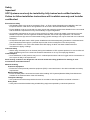
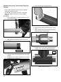
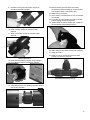
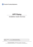
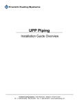
UPP Piping Systems
Electrofusion Welding Instructions
Franklin Fueling Systems • 3760 Marsh Rd. • Madison, WI 53718 USA
Tel: +1 608 838 8786 • 800 225 9787 • Fax: +1 608 838 6433 • www.franklinfueling.com
Safety
Important!
UPP Systems must only be installed by fully trained and certified installers.
Failure to follow installation instructions will invalidate warranty and installer
certification!
Electrofusion Safety
• UPP Welding Units must never be operated in Zone 1 or Zone 0 areas (Hazardous area definitions are from
European Directive 1999 / 92 / EC and guidelines can be found in the APEA Blue Book 2nd Edition).
• Ensure Welding Units are connected to a power supply that meets the requirements detailed in the user manual
and are within the requirements of any local authority or regional legislation.
• An important requirement of any type of piping system is to safely connect all metallic components to ground.
Metallic components, and more general conductive materials, due to their high capacitance, can have the
potential to store a high amount of electrostatic energy (sparks discharge can only be observed over conductive
elements).
• All exposed metal parts used in UPP System installations should be adequately grounded to a dedicated earth
ground electrode and brought to a potential equal to that of other metal parts in the close proximity.
• Use ONLY FFS EF1-110 or EF1-230 welders with UPP Piping. Do NOT use these welders with other
manufacturer’s piping or fittings.
Chemical Safety
• Where using chemicals (such as Acetone) during the installation of UPP systems products, be sure to follow all
safety guidelines given on the chemical containers themselves or on any accompanying literature.
Confined Space
• Some installation of UPP products may occur in confined spaces where a lack of oxygen and a concentration of
toxic vapors is likely to be experienced.
Such working conditions are dangerous and all local health and safety guidelines for working in such
environments should be followed.
Material Handling
Protective Equipment
• Ensure the correct personal protective equipment (PPE) is used at all times in line with local health and safety
requirements.
Material Safety Data
• Ensure all safety data is accessed and used while installing UPP Systems (Material Safety Data Sheets are
available in the download area of the UPP website).
Transport & Storage
• UPP products should be transported and stored in accordance with the guidelines contained in Section 1.
Heavy items
• Heavy items should be handled using suitable lifting equipment operated by authorised personnel.
2
Contents
Safety.................................................................................................................................2
Overview...........................................................................................................................4
Installation Guidelines.....................................................................................................4
Electrofusion Instruction.......................................................................................................... 4
Electrofusion Procedure Overview.................................................................................5
Electrofusion Preparation Details...................................................................................6
Cutting pipe.............................................................................................................................. 6
Scraping................................................................................................................................... 6
Cleaning................................................................................................................................... 7
Mark Insertion Depth............................................................................................................... 7
Marking Insertion Depth by Pre-Fitting.................................................................................... 7
Clamping . ............................................................................................................................... 8
Welding.................................................................................................................................... 8
Verify Weld Completion............................................................................................................ 9
Welding Secondary Containment Pipe And Fittings...................................................10
3
Overview
The polyethylene construction of UPP pipe allows all
connections to be joined using an electrofusion welding
process. This provides a joint which is stronger than the
pipe itself, and with no leak paths.
Electrofusion is carried out quickly and simply using
specialist tools available from FranklinFueling.
A large variety of electrofusion fittings are available,
from simple couplers (for making in-line pipework joints),
to welded terminations (for terminating double wall
secondary containment pipework) and entry seals.
Installation Guidelines
Follow the guidelines below to insure a successful
installation:
• All pipe must be cut square.
• All pipes must be scraped to remove the oxidation
area before Electrofusion.
• All Spigot fittings supplied un-bagged must be
scraped to remove the oxidation area before
electrofusion.
• Pipes, fittings and sockets must be cleaned with
acetone where they join.
• All joints should have the pipe inserted into the
electrofusion fitting ensuring that the marked
insertion depth is reached.
• Joints must not be under any stress during welding
or until ambient temperature is reached after
welding.
4
Electrofusion Instruction
Organise all necessary tools and equipment on the job
site prior to commencing the installation of pipe and
fittings.
The basic installation tool set should always include:
•UPP Electrofusion welder.
• Pipe cutter.
• Pipe Scraper.
• Cleaning Solvent.
• Straight and angled clamps.
• Permanent marker or Chinagraph pencil (white,
yellow or red).
• Tape measure.
Refer to the following sections for more detailed
information on the above tooling.
Electrofusion Procedure Overview
1
2
Measure and cut pipe to required length
allowing for correct insertion depth into
welding coupler.
3
Use one of the scraping tools provided in the
UPP installation box to prepare the pipes and
fittings for welding.
4
Clean scraped areas of pipe / fitting using a
lint free cloth moistened with Acetone.
5
Measure and mark pipe to indicate correct
insertion depth into fusion fitting.
6
Clean bore of the welding coupler with Acetone.
7
Assemble the joint and hold in place with
clamp. Check that insertion is up to the marked
depth indication.
8
Connect welder to clamped assembly and
follow welding unit instructions. Ensure
appropriate welding cables are used.
Note: Case-mounted EF1-110 shown. EF1-230
Handheld welder can also be used.
• Check insertion depth mark for movement.
• Check that welding completion indicators are out.
• Allow joint to cool to ambient temperature. Wait at
least 20 minutes before any stresses are exerted
upon the assembly.
5
Electrofusion Preparation Details
Scraping
Primary pipe (single wall pipe)
• Cut primary pipe only by using the appropriate UPP
pipe cutter tool and never using a hand saw. The UPP
cutting tool gives 100% straight cuts every time and
no burring ensuring that the cut ends fit flush into any
welding couplers or fittings.
Note: NEVER, under any circumstance, use sand paper
on primary or secondary pipe.
Cutting pipe
It is imperative that the scraping of pipes and fittings is
carried out exactly as described here to remove the layer
of oxidised material that builds up on the pipe when it is
exposed to air. This oxidised layer hinders the quality of
the weld and must be removed.
Primary pipe (single wall pipe)
Primary pipe must be scraped using the UPP
scraping tool. These tools remove a controlled outer
layer of oxidised polyethylene over the length of the pipe
which is inserted into a coupler or electrofusion fitting.
Cutting primary pipe using UPP cutting tool
• There are two different pipe cutters available for
varying pipe diameters.
Pipe Diameter
Pipe Diameter
(mm)
(inches)
P.CUT
50-110
1½-4
P.CUT MED
110-160
4-6
Secondary containment pipe (double wall pipe)
• Cut secondary containment pipe in exactly the same
way as primary pipe, using the UPP pipe cutting tools.
• When cutting coaxial pipe it is possible to cut through
both pipe layers in one go. Be careful of this if
you want your primary pipe length longer than the
secondary sheath (inside sumps and chambers etc.).
Tool
Scraping UPP Primary Pipe Using Scraping Tool
Secondary containment pipe (double wall pipe)
• Secondary containment pipe has to be scraped using
the UPP hand scraper (SCR.HAR). A layer of plastic
must be removed all along the length of pipe to be
inserted into the welding coupler or electrofusion
fitting.
Scraping UPP Secondary Pipe Using Hand Scraper
Cutting Secondary Pipe Using UPP Cutting Tool
Duct pipe
• It is not possible to cut UPP corrugated duct pipe
using the UPP pipe cutting tools. A hand saw should
be used to cut the duct using the corrugations as
guides to help create a clean, straight cut.
6
Non-Electrofusion Fittings
Non electrofusion fittings (i.e. those that need an
electrofusion coupler to be welded) if supplied Un-bagged,
must be scraped with the UPP hand scraper before
welding’
Mark Insertion Depth
Mark the insertion depth on pipe ends using a permanent
marker or China-graph pencil and a ruler
Using a Ruler to Mark Insertion Depth
Scraping UPP Non-Electrofusion Fitting with Hand Scraper
The polyethylene area of these fittings must be scraped
using the UPP hand scraper to remove a layer of oxidised
polyethylene along the whole length that is to be inserted
into the welding coupler.
Electrofusion Fittings / Welding Couplers
Electrofusion fittings are those with welding elements built
into them - these do not require scraping before being
used, but must be cleaned with a solvent (See below).
Cleaning
To ensure that there is no grease, moisture or dirt in
the electrofusion zone during welding it is important to
clean all the pieces of the assembly prior to welding. The
following solvents may be used:
• A
cetone (preferred)
• Isopropyl alcohol
• Trichloroethane
The following table shows the correct insertion
depth into UPP primary electrofusion fittings
Description
Welding
Coupler
90º Elbow
Electrofusion
45º Elbow
Electrofusion
Ø
mm
Product
Code
Insertion
Length
mm
Inches
50
02-50
25
1
63
02-63
30
1 3/16
90
02-90
36
1 3/8
110
02-110
41
1 9/16
50
03-050-EIF
44
1 3/4
63
03-063-EIF
48
1 7/8
90
03-090-EIF
62
2 7/16
110
03-110-EIF
71
2 3/4
63
04-063-EIF
48
1 7/8
90
04-090-EIF
62
2 7/16
110
04-110-EIF
71
2 3/4
Marking Insertion Depth by Pre-Fitting
The insertion depth can also be marked by inserting the
cleaned pipe fully into the fitting and marking around the
fitting.
Using An Acetone-Soaked Cloth To Clean A Welding Socket
and Seal Spigot Do NOT USE solvents that leave an oily film on the joining
surface such as turpentine, petrol or synthetic dilutents.
The surfaces to be cleaned include:
•All scraped areas of pipes and fittings
•The inside of electrofusion fittings and welding
couplers
Once the areas of pipes and fittings to be welded have
been wiped clean, avoid touching the cleaned areas or
allowing contact with any sources of grease / dirt.
Note: In wet weather, protect the fittings from water.
Water in the fittings can contaminate the welds
and cause failures.
Marking Insertion Depth
Inscribe a line around the junction of the pipe and fitting.
Note: When using this method, make sure the pipe
is fully inserted. Visually check if possible, or
listen / feel for the pipe positively contacting the
stop.
7
Clamping
Check for correct alignment of the assembly both
vertically and horizontally and ensure that it is not
subjected to any bending load or weight that could
deform to the joint while it is in a molten state.
Use UPP clamps to keep the assembly in the correct
alignment position, preventing any movement during the
welding and subsequent cooling process.
If a clamp cannot be used, for example in a small tank
chamber, precautions need to be taken to ensure that
the assembly is not under any stress.
Welding
Overview
UPP 230 volt and 115 volt intelligent Welding Units
supply the precise electrical energy to fuse two UPP
products together safely on site. The heat causes
the pipe and joint surfaces to melt and fuse. After
electrofusion, the assembly is left to cool while the
polyethylene solidifies to form a homogenous union
stronger than either pipe or fittings.
Note: UPP welders use a constant current output. UPP
components must never be welded with other
brands of welding unit.
Both types of welder can be used from the mains supply
or from a generator.
The welding machine measures the ambient temperature
and the welding coupler / electrofusion fittings resistance
values. The welder must be close to the same
temperature as the joint it is welding.
Screw Clamps
The screw clamps on some fittings are used to hold
the pipe in place for clamping. The piping may have a
pre-load force that could pull the pipe out slightly before
clamping. Tighten the screws to hold the piping in place
while the clamps are installed.
Bridging
A maximum of three primary couplers or primary
electrofusion fittings may be welded at the same time by
using bridging leads. Most electrofusion couplers and
fittings have a resistance index number marked onto
them inside a circle: i.e. ⑥. The total value of the index
number of the three items to be welded must not exceed
10. If the fitting lacks a resistance index number then it
must be treated as having an index number of 10. A list
of resistance numbers can be seen in the following table.
Description
Primary welding socket
Angled Clamp Installed
Straight Clamp Installed
8
Part number
Resistance
index number
02-50
2
Primary welding socket
02-63
2
Primary welding socket
02-90
4
Primary welding socket
02-110
6
Primary welding socket
02-160
10
Primary welding socket
02-200
10
Electrofusion elbow 90º
03-050-EIF
4
Electrofusion elbow 90º
03-063-EIF
4
Electrofusion elbow 90º
03-090-EIF
7
Electrofusion elbow 90º
03-110-EIF
9
Electrofusion elbow 45º
04-063-EIF
4
Electrofusion elbow 45º
04-090-EIF
7
Electrofusion elbow 45º
04-110-EIF
9
Electrofusion equal tee
08-050-EIF
4
Electrofusion equal tee
08-063-EIF
4
Electrofusion equal tee
08-090-EIF
7
Electrofusion equal tee
08-110-EIF
9
Electrofusion reducer
09-090-063-EIF
5
Electrofusion reducer
09-110-090-EIF
7
Electrofusion entry seal
302 Flange
1
Electrofusion entry seal
303 Flange
2
Electrofusion entry seal
305 Flange
3
Electrofusion entry seal
308 Flange
3
Verify Weld Completion
Welding Cables Chart
Type
of
Fitting
Primary
Size of
Welding
Welding
Cable
Pim
Colour
(mm)
Current
(amps)
Weld Time
@ 20C
(Seconds)
Red
4
4
184
Secondary
Green
2
5
80
Fusion
Chamber
White
2.3
7
360
Large
Diameter
(10amp)
Black
2
10
365
The first indication of a successful weld is that the
welder’s green 100% LED is lit.
Most fittings have a weld indicator built in. After the weld
the center of the indicator should protrude above the
surrounding area.
Weld Indicator
(Before welding)
Note: A resistance value of X means that there is no
marked resistance value on the fittings and these
should be treated as having values of 10.
Connect the leads from the welding unit to the fittings
per the chart above. The leads should fit firmly. It is very
important to use the correct cable.
Welding Process
After the welder is turned on, press the start button to
begin the welding process. The weld time is determined
by the welder and no further input is required.
Note: Before pushing the start button, the welder must
show a green ready light. Hold the start button down
momentarily and then release it.
The welder display will show welding progress. Once
completed it is good practice to write the time on the
fitting to determine when clamps can be removed.
Weld Indicator Location
Weld Indicator
(After welding)
Wait 20 minutes for the weld to cool before removing
clamps.
Resetting the welder
Always reset the welder between welds by depressing
and holding the start button for 3 seconds.
Weld Indicator Completed
Look in the Tightness Testing Section for complete
inspection procedure.
Troubleshooting
• Refer to the welder documentation for complete
welder operation and error codes.
• If power is lost during the weld, allow the fitting to cool
in place for at least an hour and then restart the weld
process.
9
Welding Secondary Containment Pipe And
Fittings
5. Clean primary pipe end with acetone.
• Green welding cables should be used for welding
secondary containment pipe
• Some welding unit displays will read: “Secondary
Mode” and after five seconds “Connect welding
element”
Procedure
1. Cut Co-axial pipes to required length using the
pipe cutter as shown.
Clean Secondary with Acetone
6. Pre-clean secondary pipe 200 mm (8.0") from
end.
7. Clean reducer with acetone and slide it along
secondary pipe - small end first.
Cut Secondary Pipe
2. Trim or slide the secondary pipe back 40 mm
(1 9/16").
Slide Reducer on Secondary
40 mm (1 9/16")
8. Ensure elbow or tee primary spigots measure
30 mm (1 3/16"), and cut to length if required.
30 mm
(1 3/16")
Trim or Slide Secondary
3. Prepare primary and secondary pipe using hand
scraper.
4. Secondary pipe must be scraped all the way up
to 150 mm (6.0") from its end.
m
150 m ")
0
.
(6
10
Scrape Secondary
Measure Primary Spigots
9. Prepare Primary and Secondary spigots of
tee / elbow with hand scraper.
15. Before welding check that the secondary
containment reducer is fitted in correct location
over scraped zone of secondary pipe.
16. Weld Primary couplers.
17. Once weld is complete allow to cool for at least
30 minutes.
18. If needed, do not weld the secondary until the
primary piping has been inspected.
19. Clean inside of reducer spigot and outside of
the Tee / Elbow spigots with acetone.
Scrape Primary and Secondary
10. Clean Primary spigots of tee / elbow with
acetone.
11. Clean Secondary spigots of tee / elbow with
acetone.
Clean Inside of Secondary
Clean with Acetone
20. Slide reducers into place (ensure full insertion).
21. Weld secondary.
22. Allow to cool for at least 30 minutes before
putting any stress on the joint.
12. Clean primary welding coupler using acetone.
13. Fit couplers to primary Tee / Elbow spigots.
Assembled Secondary Fittings
Clean Weld Coupler with Acetone
14. Insert Primary pipe into welding couplers (ensure
pipe is fully inserted).
Insert Primary Pipe into Coupler
11
©FFS 2011 408001007 Rev1
Franklin Fueling Systems LTD
8 Olympus Close • Whitehouse Industrial Estate
Ipswich, Suffolk IP1 5LN • United Kingdom
Tel: +44 1473 243300 • Fax: +44 1473 243301