1
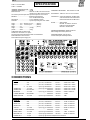
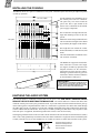
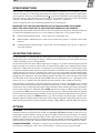
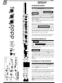
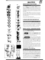
GL2
INTRODUCTION
The GL2 continues ALLEN & HEATH’s commitment to provide high quality audio mixing consoles engineered
to meet the exacting requirements of today’s audio business. It brings you the latest in high performance technology
and offers the reassurance of over two decades of console manufacture and customer support.
This user guide presents a quick reference to the function, application and installation of the GL2. For further
information on the basic principles of audio system engineering please refer to one of the specialist publications
available from bookshops and audio equipment dealers.
Whilst we believe the information in this guide to be reliable we do not assume responsibility for inaccuracies. We
also reserve the right to make changes in the interest of further product development.
SERVICE AND TECHNICAL SUPPORT
Under normal conditions the GL2 does not require user maintenance or internal calibration. Any service work
required should be carried out by qualified service personnel only.
We are able to offer further product support through our worldwide network of approved dealers and service agents.
To help us provide the most efficient service please would you keep a record of the console serial number, and date
and place of purchase to be quoted in any communication regarding this product.
SAFETY WARNING !
Mains electricity is dangerous and can kill. Mains voltage is present within the console power
unit. Do not remove the internal power unit or rear cover with mains connected. Check your
mains wiring and earthing before switching on.
DO NOT REMOVE THE MAINS EARTH CONNECTION!
The console chassis is always connected to mains earth to ensure your safety. Audio 0V is
connected to mains earth within the power unit. Operating the ground lift switch on the rear
panel of the unit will separate audio 0V from mains earth. This switch can be used to avoid
problems with ground loops.
PRECAUTIONS.
l
AC POWER:
l
CONNECTIONS: Use audio connectors and cables only for their intended purpose. Do not connect any
source of AC or DC power to the console audio connectors. Do not connect the output
of power amplifiers directly to the console.
l
CLEANING:
Avoid the use of chemicals, abrasives and solvents. The control panel is best cleaned
with a soft brush and lint-free cloth. To remove stubborn marks (such as chinagraph
pencil) isopropyl alcohol may be used.
l
LUBRICATION:
The faders, switches and potentiometers are lubricated for life. The use of electrical
lubricants on these parts is not recommended.
l
DIRT, DUST, SMOKE and MOISTURE: Prevent damage to the moving parts, such as faders and
potentiometers, and cosmetics by avoiding drinks spill age, tobacco ash and smoke, and
exposure to rain and condensation. Protect from excessive dirt, dust, heat and
vibration.
Check the power supply label for the correct AC mains voltage setting. Allow adequate
space behind the console for ventilation.
copyright © 1993 ALLEN & HEATH Ltd. All rights reserved
Publication ...................... AP0177 Issue 1
GL2
THE GL2
The ALLEN & HEATH GL2 offers the flexible solution to the many requirements of the live sound and recording
environment; whether for conference sound ... in a club ... theatre .. or church ... for touring ... contract hire ... as
well as stereo and multitrack recording. The key to this versatility is the unique switching arrangement which
configures the console for Front-of-House or On-stage Monitor operation, or a combination of both. 6 Aux sends
switchable in combinations of pre or post fader, a powerful 4-band 2-sweep equaliser, dedicated stereo channels,
and comprehensive monitoring facilities combine in a compact all metal rack mount chassis to allow total and
reliable control of the mixed sound whatever the application.
FEATURES
The choice of console operating mode at the press of a switch:
FRONT-OF-HOUSE
t
t
t
t
t
Wide range 4 band 2 sweep channel equaliser with in/out switch
6 aux send controls with pre/post fader switching on 1-4 and 5,6
Balanced XLR Left, Right and Mono outputs
4 balanced XLR group outputs with subgrouping to stereo
Comprehensive master section providing pre or post fader L-R monitoring, auto PFL/AFL, and 2-track
record facility.
STAGE MONITOR
t
t
t
t
Balanced mic and line inputs with wide ranging pre-amp and 4-band EQ
6 stage monitor sends with pre/post fader switching on 1-4 and 5,6
6 balanced XLR stage monitor outputs with inserts, metering and signal checking
Comprehensive master section providing headphones monitor and separate engineers wedge output
RECORDING
t
t
t
t
4 group outputs with 4 tape monitor inputs for multitrack recording
Separate stereo mix and 2 track record outputs
2 track tape monitoring
10 mono and 2 stereo input channels
PLUS
t
t
t
t
t
t
t
t
t
MULTIMODE OPERATION configures the GL2 as a stereo + mono F.O.H console with 4 full feature stage
monitor sends and 2 effects sends
2 dedicated stereo channels with dual input sources, separate left and right connectors, EQ and full routing
3-point peak indicators on channel inputs
Mute switches, AFL checking and peak indicators on group and L-R outputs
Inserts on channel inputs, groups and L-R outputs
Electronically balanced channel inputs and group, L-R and mono outputs
Internal power unit with ground lift switch
Compact all metal construction for rack or plinth mount, and adaptable for table top operation.
Professional quality assembly with individual circuit assemblies, 100mm long throw faders, and quality
components used throughout to ensure continued reliability and exceptional audio performance.
GL2
SPECIFICATION
0 dBu = 0.775 Volts RMS
0 dBV = 1 Volt RMS
INTERNAL OPERATING LEVEL: -2 dBu
INTERNAL HEADROOM: ............ +23 dB
MAX OUTPUTS: .......................... balanced +27 dBu 600 ohms max load
unbalanced +21 dBu 2kohms max load
All console inputs and outputs are in-phase except for the GROUP INSERTS
METERS: ..................................... Peak responding bargraph
0VU = +4dBu at XLR outputs
PEAK LEDs: ................................. Turn on 5dB before clipping
SIG LEDs: .................................... dynamic responding Turn on at -20dBu
Width ............... 19.0" standard 19" rack .......... (483mm)
Height .............. 19.2" 11U rack space ............. (488mm)
Depth ............... 3.5" ........................................... (90mm)
weight .............. 21lbs ................... (10.5kg)
packed ............. 28lbs ................... (13kg)
CONSTRUCTION: All metal chassis.
Standard 19" rack mount in 11U space.
Single front panel with individual removable circuit assemblies.
Removable base for service access.
Removable internal power supply unit.
FREQUENCY RESPONSE: 20Hz to 20kHz +0/-1dB
DISTORTION: . THD 0.01% Line in to mix out at 1kHz
CROSSTALK: . output mute better than 100 dB at 1kHz
channel mute better than 90 dB at 1kHz
fader shutoff better than 90 dB at 1kHz
NOISE: ............ 22Hz to 22kHz
MIC EIN -127.5 dB into 150 ohms
LINE pre-amp at 0dB -88 dBu
MIX noise -85 dB ref 0VU
POWER REQUIREMENTS: 50/60Hz 40W max
Mains voltage set for local requirements.
PHANTOM POWER: +48V DC 50mA
Channel XLR inputs individually switched
CONNECTIONS
INPUTS:
MIC IN ............................ XLR ............................ pin 2 hot, 3 cold balanced .......... 2 kohms ........... variable -60 to -10dBu
LINE IN .......................... XLR ............................ pin 2 hot, 3 cold balanced .......... 10 kohms ......... variable -40 to +10 dBu
or
1/4" JACK .................. tip hot, ring cold balanced .......... 10 kohms ......... variable -40 to +10 dBu
STEREO IN A ................ 1/4" JACK .................. tip hot, ring cold unbalanced ...... 20 kohms ......... variable -20 to +22 dBu
STEREO IN B ................ RCA PHONO ....................................... unbalanced ...... 20 kohms ......... variable -20 to +22 dBu
RETURN IN ................... 1/4" JACK .................. tip hot, ring gnd unbalanced ...... >10kohms ........ variable -10 dBV min
2-TRACK RETURN ....... RCA PHONO ....................................... unbalanced ...... >6 kohms ......... -10 dBV
INSERT RETURN .......... 1/4" JACK .................. tip send, ring ret unbalanced ...... >6 kohms ......... -2dBu
OUTPUTS:
L-R OUT ........................ XLR ............................ pin 2 hot, 3 cold balanced .......... 50 ohms ........... +4 dBu +27 dBu max
MONO OUT ................... XLR ............................ pin 2 hot, 3 cold balanced .......... 50 ohms ........... +4 dBu +27 dBu max
GROUP OUT ................. XLR ............................ pin 2 hot, 3 cold balanced .......... 50 ohms ........... +4 dBu +27 dBu max
AUX OUT ....................... 1/4" JACK .................. tip hot, ring gnd unbalanced ...... 75 ohms ........... variable +21 dBu max
2-TRACK SEND ............ RCA PHONO ....................................... unbalanced ...... 1 kohm ............. -10 dBV
INSERT SEND ............... 1/4" JACK .................. tip send, ring ret unbalanced ...... 75 ohms ........... -2 dBu . +21 dBu max
MONITOR OUT ............. 1/4" jack ..................... tip left, ring right unbalanced ...... 100 ohms ......... variable +21 dBu max
PHONES OUT ............... 1/4" jack ..................... tip left, ring right for stereo headphones 8 to 400 ohms
GL2
INSTALLING THE CONSOLE
The GL2 fits into an 11U space in a standard 19" rack system. Alternatively the console may be adapted for plinth
or table top operation.
19" rack width
Provide adequate space behind the rear of
the console power unit for ventilation.
The panel may feel warm around the
power unit. This is quite normal as the
chassis acts as a heatsink for the internal
power supply components.
The two M3 base securing bolts each side
align with mounting recesses in the rack
system.
11U space
Mount the console using 4x M6 bolts each
side for maximum strength. These should
be provided by the supplier of the rack kit.
The height does not include the control
knobs (add 20mm) or connector nuts (add
8mm).
The rack should allow a minimum side to
side clearance of 450mm.
The GL2 has two support feet fitted to the
front of the base to set the correct angle
(14 degrees) for table top operation with
adequate clearance for the connectors.
Support the rear of the console to achieve
this angle. Operation in this way prevents
interference with the connectors and takes
up the minimum of table space.
PRECAUTION !
TO AVOID DAMAGE TO THE INTERNAL ASSEMBLIES DO NOT
FIT SCREWS THROUGH THE HOLES IN THE SIDES OF THE
CONSOLE. SECURE TO EXTERNAL BRACKETS OR FITTINGS
THROUGH THE TOP PANEL RACK MOUNTING HOLES.
EARTHING THE AUDIO SYSTEM
The console chassis is connected to mains earth via the power cord. FOR SAFETY REASONS NEVER
REMOVE THE EARTH WIRE FROM THE MAINS PLUG. The console audio 0V is connected to mains earth
within the console power unit by the ground lift switch. To prevent mains born and external interference pick-up
on the audio signal it is important that this audio 0V is connected to a good noise-free mains earth, either through
the audio cable screens or by linking to a local earth. Multiple earth paths cause earth (ground) loops which may
result in audible hum and interference. These may be avoided by making sure that there is only one path to earth
from each piece of equipment, disconnecting audio cable screens at one end if necessary.
Selecting the ground lift switch on the rear of the console disconnects the console audio 0V from the chassis (mains)
earth. This avoids ground loops in situations where the chassis metalwork is in physical contact with another path
to earth, (often the case in 19" rack installations), or if audio 0V connects to mains earth elsewhere in the system.
Ground lift switch located on
rear of the console power unit.
Press to disconnect audio 0V
from mains earth.
GL2
INTERCONNECTIONS
Where possible use balanced connections for the channel INPUTs and GROUP, L-R and MONO outputs to
minimise noise pick-up. Avoid running audio cables near to mains or lighting cables or thyristor dimmer units,
power supplies etc. These may cause audible hum and buzz. The use of low impedance sources significantly reduces
interference pick-up. Check the cables for correct wiring to avoid problems with phase reversal and unreliable
connection. The GL2 follows the convention for XLR pin 2 and jack tip = signal hot (+).
Always use balanced cables when connecting to phantom powered microphones.
MAKE SURE THAT THE +48V SWITCHES ARE OFF (UP POSITION) WHEN THE CHANNEL
INPUT XLRS ARE CONNECTED TO NON-PHANTOM POWERED OR LINE SOURCES.
If ground loops cause problems connect the cable screen at one end only as described below. Balanced outputs may
be connected to unbalanced inputs and vice versa by linking the signal cold (-) to 0V ground as follows:
t
Balanced output to Balanced input - Connect cable screen at destination only.
t
Balanced output to Unbalanced input - Connect screen at source only. Link the -ve output to 0v at the output
connector.
t
Unbalanced output to Balanced input - Connect cable screen at destination only. Link the -ve input to 0V
at the input connector.
ADJUSTING THE LEVELS
For best performance it is important that the console signal levels are adjusted for “normal operating level”. If too
high the signal peaks will be clipped resulting in a harsh distorted sound, and if too low the signal-to-noise ratio
is reduced resulting in excessive background hiss.
For best results operate the console with the output meters averaging ‘0’ or just below and allowing the occasional
high level passage to rise into the red. This results in a nominal console output level of +4dBu with ample internal
headroom of +23dB to allow for the peaks. It is advisable to use an attenuator pad if you are connecting the outputs
to equipment which does not have input level controls and operates at a much lower level. Simply reducing the fader
settings (and hence meter levels) to compensate may result in excessive background noise and breakthrough due
to the reduced signal-to-noise ratio. The same applies to the console monitor output used to check the console signals
through reference loudspeakers. The monitor amplifier should be matched to the console such that normal control
room listening levels are achieved with the monitor LEV control set around position '5' to '7'. Operating at a lower
position, say '2' or '3', degrades the output signal-to-noise ratio and may result in audible hum and noise.
The console PFL (pre-fade listen) / AFL (after-fade listen) system lets you listen to and check the level of signals
at different points in the signal path without affecting the main outputs. Use the channel PFL switches to set up
the input levels. This overrides the phones/monitor outputs with the pre-fader channel signal (in mono) and displays
its level on the monitor meters. Adjust the channel GAIN controls for an average '0' reading on the meters. Use the
aux, group and L-R AFL switches to check the post master fader mix levels. Adjust the channel faders for optimum
mix level. The normal operating setting of the faders is at the '0' position, allowing 10dB of boost to the top of travel.
The red channel and group, L-R PEAK indicators give instant warning of potential signal overload. These
illuminate 5dB before clipping. Reduce channel gain or fader settings as appropriate. Each Group fader has a meter
ladder showing signal presence (dynamic indication starting at -20dB), 0dB level, and peak (5dB below clipping).
OPTIONS
AUX SENDS: Aux 1-4 and aux 5,6 are switched pre or post fader using panel switches to satisfy most applications
without the need to access internal circuits. Pre-fade is set pre-EQ and post-mute as standard. Contact your service
agent should you require alternative settings. An option is available to balance the aux jack outputs. Note that the
standard aux outputs are low impedance high level line signals which are interference free and do not require
balancing unless extremely long cables are connected in the presence of high level interference and hum fields. The
options should be fitted only by competent technical personnel who have reference to the GL2 service manual.
CONSOLE EXPANDER: The GL2 Sys-link option may be installed such that two GL2 consoles operate as one
in a master/slave arrangement. This is not a user fitted option. Contact your service agent for details.
GL2
INPUT
MATCHING THE INPUT
PRECAUTION !
ALWAYS MAKE SURE THAT +48V SWITCHES ARE OFF
(UP POSITION) WHEN THE CHANNEL INPUT XLRS ARE
CONNECTED TO NON-PHANTOM POWERED OR LINE
SOURCES.
A wide-ranging padless input pre-amplifier matches the
connected audio source to the console. Use the PFL system
to set GAIN for the correct internal operating level (0dB
on the meters). Centre position provides +10dB line gain.
MIC/LINE selects a balanced mic or line XLR source.
Connecting to the additional 1/4" jack balanced line input
automatically overrides the XLR line input.
For MIC INPUT only connect to the XLR socket. Select
MIC (or LINE to provide a 20dB pad for very high output
microphones).
For LINE INPUT only connect either to the XLR or jack
connector and select LINE.
For MIC AND LINE INPUT selectable using the switch
connect mic to the XLR and line to the jack socket.
Individual +48V phantom power switches are located on
the rear panel, recessed to prevent accidental operation.
Use only with phantom powered microphones connected
with correctly balanced cables.
4-BAND EQUALISER
Shelving HF, LF and two wideband peak/dip mid sweeps
provide 14 dB of cut and boost.
EQ IN switches the equaliser in or out of the channel path.
Centre detents set the response flat.
The normalled INSERT socket provides a
pre-EQ -2dBu break point for inserting an
external efftects or signal processing device into the channel path. This may also be
wired as a pre-fade direct output by linking
send to return in the plug and tapping the
signal from this point.
Use the PFL system to match the inserted
device to the operating level of the channel.
6 AUX SENDS
6 individual sends with 1-4 and 5,6 switchable pre/post
fader provide effects and foldback sends for recording or
F.O.H., or monitor mix sends for ON-STAGE console
operations. Internal links for the pre-fade sends are set as
standard to pre-EQ (post-EQ option) and post-mute
(pre-mute option).
ROUTING
Centre detented PAN positions the signal between L (odd)
and R (even) of the selected groups/L-R mix. This
positions the signal as required in the stereo image, or may
be used to route to single mono outputs only. The 100mm
long throw FADER provides a further 10dB boost above
the normal ‘0’ operating position. MUTE switches the
channel off.
CHECKING THE SIGNAL
The red PEAK LED warns of potential overload 5dB
before clipping at any of 3 key points in the channel path.
Pressing PFL routes the pre-fade signal to the console
monitor/meter system to check sound quality and gain
setting. The PEAK LED will illuminate at HALF brightness when the PFL switch is pressed.
GL2
STEREO
MATCHING THE INPUT
For
INPUT A
set the IN A/B switch up.
For
INPUT B
set the IN A/B switch down.
MONO combines the left and right inputs to mono the
source, or may be used to input a mono source to the
stereo channel path.
The GAIN control allows a wide range of equipment to
be correctly matched to the console.
4-BAND EQUALISER
Shelving HF and LF and two fixed frequency peak/dip
mid controls provide 14dB of cut and boost.
EQ IN switches the equaliser in or out of the channel
path. Centre detents set the response flat.
DUAL INPUT
6 AUX SENDS
The stereo channel features a dual
input which selects between two
alternate stereo sources. This is ideal
for fast switching between stereo
sources without the need to re-patch
the console. It also allows connection to standard leads with either
jack or phono plugs.
6 individual sends with 1-4 and 5,6 switchable pre/post
fader provide effects and foldback sends for recording or
F.O.H., or monitor mix sends for ON-STAGE console
operations. Internal links for the pre-fade sends are set
as standard to pre-EQ (post-EQ option) and post-mute
(pre-mute option).
The stereo channels may also be
used for returns from stereo effects
processors, providing full EQ, signal checking, routing and feeds to
foldback monitors. To avoid feedback do not send the return back to
itself through its post-fade aux send.
The L and R stereo signals are combined to provide the
aux feeds in mono.
ROUTING
The PAN control changes its characteristics depending
on the MONO switch status. In stereo, PAN functions
as a balance control, usually to adjust for imbalance in
the source. In mono it provides true pan to position the
signal in the stereo image.
The 100mm long throw FADER provides a further
10dB boost above the normal ‘0’ operating position.
MUTE switches the channel off.
CHECKING THE SIGNAL
The red PEAK LED warns of potential overload 5dB
before clipping at the pre-fade L and R channel points.
Pressing PFL routes the pre-fade signal in mono to the
console monitor/meter system to check sound quality
and gain setting. The PEAK LED will illuminate at
HALF brightness when the PFL switch is pressed.
GL2
GROUP
OPERATING MODE
The recessed GRP/AUX REV switch determines the
way in which the group signal path is arranged.
For conventional operation
FRONT-OF-HOUSE
or RECORDING (switch up) the group mix is routed
to the main signal path through the insert, FADER and
MUTE switch to the balanced XLR output, while providing subgrouping, AFL monitoring, signal and PEAK
metering. The related aux mix routes through the rotary
SEND MASTER level control to the 1/4" jack aux
output, with AFL monitoring available, to provide an
effects or foldback send.
With the switch pressed (using a pen tip or similar) the
group and aux mix is reversed so that the signal path is
optimised for ON-STAGE MONITOR operation.
This feeds the aux mix through the main signal path to
provide a full feature balanced stage monitor send. In
this mode the group mix is rerouted to the related aux
jack output through its send master and is available for
additional monitor, effects or sub sends.
It is advisable to study the GL2 system block diagram to
fully understand this flexible routing arrangement.
RETURN/SUBGROUP
To RETURN processed signals from external effects
devices or input additional line signals to the L-R mix,
or for TAPE MONITORING during multitracking,
set the RET/GRP switch to the up position. Use the
LEV and centre detented PAN controls to adjust the
level and stereo image.
SUBGROUPING enables several sounds to be combined under control of a single fader and then routed to
the main L-R mix. To set up a subgroup route the
required channels to a group, press the GRPswitch, and
adjust LEV and PAN for the desired level and stereo
image in the L-R mix. Using the channel and subgroup
PAN controls it is possible to set up mono or stereo
subgroups.
CONTROL OF THE OUTPUTS
The main outputs (group or aux mode as selected) are
controlled by the 100mm long throw FADERS which
offer a further 10dB boost above the normal '0' operating
position. MUTE switches off the output.
Pressing AFL routes the post-fader signal to the console
monitor/meter system to check sound quality and mix
level. The AFL signal is pre-mute to allow the output to
be muted if required while checking the signal.
Each main output has a dedicated post-fader LED
metering system. SIG responds dynamically to the
audio signal starting to illuminate around -20dB level.
0dB turns on at the console 0dB level (-2dBu internal).
PEAK warns of potential overload 5dB before clipping.
GL2
MASTER
MONITORING THE SYSTEM
The PHONES/MONITOR section allows the engineer to
listen to L-R (aux 5-6) either PRE or POST the master
faders, or 2-TRACK return through up to two pairs of stereo
headphones or monitor speaker systems while displaying the
selected source on the L and R monitor meters. The peak
responding LED bargraph meters are positioned above each
group strip.
Pressing any AFL or PFL switch interrupts left and right of
the monitor with the selected signal in mono and displays
AFL (AFL active LED on) or PFL (PFL or AFL+PFL LED
on) on both meters.
Source selection follows this priority:
PFL overrides AFL overrides 2-TRACK overrides L-R PRE overrides L-R POST
2-TRACK RECORD AND REPLAY
2 pairs of phono connectors, SEND and RETURN, allow
convenient connection to a 2-track recorder such as cassette
or DAT. The send may also be used as an additional
unbalanced L-R output. These connections are set as standard for low level operation (-10dBV). For high level
recording the balanced L-R XLR outputs may be used.
MONO OUTPUT OPERATING MODE
The recessed MONITOR MODE switch determines the
function of the balanced mono output.
For F.O.H. applications (switch up) the main L and R
outputs are summed to drive a centre MONO FILL speaker
system. Alternatively this output may be used for mono
recording or to provide a mono broadcast feed.
For ON-STAGE operation (switch pressed) this output
becomes AFL interrupted by PFL to drive an engineers
WEDGE MONITOR system. The wedge mix is created by
pressing the required aux (group) AFL switch combination
to listen to the monitor send mix. Pressing any PFL switch
allows the engineer to check the channel signals, for example
while setting the gains or EQ.
On-stage monitor systems usually include a graphic equaliser on each monitor feed adjusted to tune out the resonances
which cause acoustic feedback. These equalisers should be
patched into the console group inserts so that their effect may
be monitored when AFL is pressed.
THE MAIN L-R OUTPUTS
The L and R output section is identical to the group section
with aux reverse switching which configures the main
outputs for aux 5, 6 when required. Note that the subgroups
always route to the L-R mix and are therefore present at the
aux 5, 6 outputs when reverse is selected. It is possible to set
up an additional stereo or two mono monitor sends from a
combination of monitors (aux) 1 to 4 when SUBGROUP is
selected. Alternatively the four return inputs provide a fully
independent stereo sub mixer when RETURN is selected.
GL2
MONO
FRONT-OF-HOUSE
conference ... club ... disco ... live shows ... theatre ... church ... touring ...
RIGHT
LEFT
3
4
1
2
5
FOLDBACK
6
pre-fade aux sends
1
EFFECTS
2
groups
3
4
insert
sends
returns
COMPRESSOR/LIMITERS
These are often used to prevent excessive
peaks overloading the amplification
system, for example in club installations
subject to sound level control.
This example shows the 4 groups, L, R, and
Mono outputs feeding a 7 stack FOH amplification system. The groups provide independent
control of the additional left and right loudspeaker stacks, or may be used for separate
effects or zone feeds, or for subgrouping to the
L-R mix.
Select aux 1 to 4 post-fade to access 4 effects
processing devices. Use Return inputs 1 to 4 to
add the effects to the L-Mono-R outputs. Alternatively use the stereo or mono channels to mix
the effects into the groups and foldback as well.
Select aux 5 and 6 pre-fade for 2 foldback
monitor sends.
The channel and output inserts may be used for
floating effects and signal processing devices
such as compressors, limiters and graphic equalisers.
up
POST
PRE
up
These switches are
recessed
to
avoid
accidental operation. Set
using a pen tip or pointed
object.
Set the MONITOR
MODE switch to the up
position for mono out (L+R
sum).
Set the REV switches to
the up position for
conventional group/LR
operation.
GL2
ON-STAGE MONITOR
On-stage mixing system for local control of performers monitor loudspeakers (wedges)
With dedicated output for the stage engineers wedge loudspeaker.
STAGE MONITORS
1
6
5
2
3
mic
splitter
4
AMPLIFIERS
ENGINEERS WEDGE MONITOR
Set up the WEDGE MIX by selecting one
or a combination of the group/L/R AFL
(monitor 1 to 6) switches to listen to the
desired stage monitor outputs. These are
post insert (post graphic EQ) and post
output fader for accurate monitoring.
insert
Pressing any PFL switch automatically
overrides the selected AFL source to allow
channel setup and signal checking.
EFFECT
EQUALISERS
to FOH
console
inserts
Graphic equalisers plugged into the console inserts are an invaluable aid to reducing
on-stage acoustic feedback and enhancing the clarity of the monitors. Using the
inserts allows the stage engineer to check the operation of the equalisers in his wedge
monitor. It is best to use the same type of loudspeaker for the engineers monitor as
the stage monitors.
These switches are recessed
to avoid accidental
operation. Set using a pen
tip or pointed object.
This example shows the 6 aux sends routed
through the main outputs to provide 6 independent stage monitor mixes with metering,
mutes, AFL, inserts and balanced XLR connectors.
The REV switches reroute the groups and L-R
mix to the aux jack outputs for additional monitor or effects sends, or as an independent submix
facility. For example the aux 5 and 6 jack
outputs may provide a separate stereo mix output fed from the channel L-R switches and the
additional 4 return line inputs.
To add effects such as delay or ADT to the stage
monitors the signal/s may be routed to a group
(available at the aux jack output), using the
master LEV to control the send level, and
returning the effect to an unused channel using
the aux send controls to set the required amount
of effect to each monitor.
POST
down
POST
down
Set the MONITOR MODE
switch to the down position
(below panel) for the wedge
monitor output (AFL
interrupted by PFL).
Set the REV switches to
the down position to route
the aux mix through the
main outputs to provide the
stage monitor sends.
GL2
MONO
MULTIMODE
L-M-R Front-of-House system with 4 dedicated stage monitor sends.
RIGHT
LEFT
3
4
STAGE MONITOR
2
1
STAGE MONITOR
EFFECTS
groups
(aux 1-4)
aux 5, 6
insert
return 1, 2
EQUALISERS
inserts
COMPRESSOR/LIMITERS
Signal processors such as these are
useful to prevent excessive peaks
overloading the amplification system.
To tune out stage resonances to prevent
acoustic feedback. These may
alternatively be positioned on stage in
series with the amplifier feeds for
performer control.
This example shows the GL2 configured to
control a Left, Centre, Right Front-of House
system with 4 full feature stage monitor
sends.
Aux 1-4 are set pre-fade for the monitor
sends so that the send level is not affected by
the F.O.H. mix.
Aux 5 and 6 are set post-fade to access two
effects devices whose outputs are added to
the L-R mix via return inputs 1 and 2.
Alternatively these may be returned via the
channels, useful for stereo effects devices.
The channel and output inserts may be used
for floating effects and signal processing
devices such as compressors, limiters and
graphic equalisers.
up
pre
These switches are
recessed
to
avoid
accidental operation. Set
using a pen tip or pointed
object.
Set the MONITOR MODE
switch to the up position
for mono out (L+R sum)
post
up
down
Set the L and R REV
switches to the up position
for L-R F.O.H. feeds
Set the group 1-4 REV
switches to the down
position to route the aux
mix through the main
outputs to provide 4 stage
monitor sends.
GL2
RECORDING
stereo amplifier
stereo and multitrack ... studio ... live ... location ... audio visual ... production ...
LEFT
RIGHT
MUSICIANS CUE
MONITOR LOUDSPEAKER SYSTEM
stereo
amplifier
outputs
inputs
Y-splitters
(or repatch leads as required)
4-TRACK MULTITRACK
line ins
groups
returns
2-TRACK RECORDER
send
return
aux 5
aux 6
COMPRESSOR/LIMITERS
Here, a typical small STUDIO RECORDING setup
is shown with 4-track multitrack and 2-track mastering recorders (ideal for hard disk and DAT recording
systems). The dedicated 2-track sends or the balanced
L,R outputs may be used to feed the 2-track.
For LIVE RECORDING the channel inserts may be
tapped (link send to return) to provide additional prefade direct feeds to a multitrack.
PATCHED EFFECT
MULTITRACKING: To
monitor the track returns select
RET and adjust LEV and PAN for
the required monitor mix.
Alternatively, use the channel line
inputs if a dedicated musicians cue
feed (aux 5,6) is required.
Select aux 1 to 4 post-fade for the effects processors.
Two stereo devices are illustrated here with their
outputs returned to the stereo channels. Additional
floating effects devices may be patched into the channel or output inserts as shown.
The additional rear panel phones/monitor output feeds
the studio reference loudspeaker system to monitor the
console signals and recorded tracks without interrupting the recording itself.
STEREO EFFECTS
1
These are often used in location recording to prevent
unexpected signal peaks overloading the recorder.
Select aux 5 and 6 pre-fade to provide a stereo cue to
the musicians headphones. Alternatively these may be
set post-fade for additional effects and the L,R outputs
used for cue.
2
POST
PRE
To monitor the group sends to the
multitrack select GRP.
MIXDOWN: Use GRP for
subgrouping or RET for effects
returns. Mix the track returns
through the channel line inputs.
up
Set the REV
switches to the up
position for group
(track) and L-R
outputs.