1
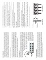
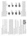
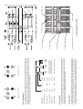
Signex UK Limited, 21A Hankinson Road, Bournemouth, BH9 1HJ, UK
Tel: +44 (0)1202 247000
Fax: +44 (0)1202 247001
Email: [email protected]
Web:
www.signex.com
All dimensions in mm
Net weight . . . . . . . . . . . . . . . . . . . . . . . . . . . . . . . . . . . . . CPJ48J . . . 970g
CPJ48P. . . 890g
CPJ48T . . . 780g
Dimensions (mm) . . . . . . . . . . . . . . . . . . . . . . . . . . . . . . . . CPJ48J . . . 483(W) x 45(H) x 81(D)
CPJ48P. . . 483(W) x 45(H) x 71(D)
CPJ48T . . . 483(W) x 45(H) x 70(D)
Min. rack opening required - 442
Switch contact life . . . . . . . . . . . . . . . . . . . . . . . . . . . . . . . . >10,000 operations
Switch contact resistance . . . . . . . . . . . . . . . . . . . . . . . . . . <30mV
Normalising . . . . . . . . . . . . . . . . . . . . . . . . . . . . . . . . . . . . Half and Full normalising
programmable on every channel
Rear termination. . . . . . . . . . . . . . . . . . . . . . . . . . . . . . . . . CPJ48J . . . ¼" type A Jack sockets
CPJ48P. . . RCA phono sockets
CPJ48T . . . Direct solder terminations
Front sockets . . . . . . . . . . . . . . . . . . . . . . . . . . . . . . . . . . . ¼" type A Jack sockets
Specifications
All Signex products are unconditionally guaranteed against defective materials and manufacture for a
period of twelve months from the date of purchase. Should any fault occur during this period, please
return the unit either to the dealer from whom it was purchased, or direct to Signex at the address below
stating when and where it was purchased and the nature of the fault. We will repair or replace the unit
at our discretion. This guarantee does not affect your statutory rights as a consumer.
Guarantee
The Isopatch is designed to be fitted into a standard 19" equipment rack with four screws that locate
through the mounting slots in the front panel. Some manufacturers make equipment racks to nonstandard specification and these may not have the required clearance between the mounting strips, so
please check the dimensions in the specifications if you are in any doubt. To avoid damage to the front
panel, use plastic or fibre washers under the screw heads. As the front panel metalwork is isolated
from the circuitry, it should not be necessary to use special isolation fixings. For electrical bonding of
the metalwork, there is a chassis ground point 'G' on the top PCB. Once the Isopatch is mounted into
the rack, the rear connection cables must be supported in some way. This can sometimes be achieved
by securing the cables to the inside of the rack, but if not, a Lacing bar (LBK01) must be used in order to
prevent the weight of cables from straining the PCB/panel assembly.
Installation
PRO AUDIO PRODUCTS
CPJ48
ISOPATCH
CPJ48
ISOPATCH
USER GUIDE
4. The insert point can then be connected to the mixer with a standard 3 pole Jack to Jack lead,
plugged into the top rear socket. The bottom rear socket is not used.
The new Isopatch retains many of the strengths of the original design, but the 1U panel now has 48
Jacks which are of a new, fully enclosed design that helps to keep out the contaminants that shorten
contact life. Like its predecessor, the new Isopatch has all sockets mounted on two horizontal PCBs
that eliminate internal wiring and give the unit inherent rigidity. Supplied with all sockets isolated, half
and full normalising can be easily programmed on any channel by soldering across special 'program
pads' on the top PCB. The use of flexible jumper cables to carry normalising signals between top and
bottom sockets allows full access for servicing. Suitable for balanced, unbalanced and stereo signals,
the new Isopatch is available with Jack, RCA phono or direct solder terminations at the rear.
In order to minimise the number of patch cords used on the Isopatch during normal operation, internal
links can be set up between pairs of sockets so that 'normal' connections can exist without any patch
cords. This feature is called normalising or normalling and is particularly useful where mixer insert
points are brought up to the patchbay to enable effects to be inserted quickly and easily. Normalising
allows a link to be set-up internally between a pair of sockets (top and bottom) so that ‘normal’ operation
can take place without a patch cord. When an effect needs to be inserted, a patch cord is inserted and
the link between the two sockets is broken. This happens because the normalising link is wired via a
switch on the socket that is operated by insertion of the plug.
Normalising socket pairs
Labelling the sockets on the front panel is neat and easy with our slide-in ident card system. The ident
card can be marked using almost anything from ball-point pen to dry-transfer lettering, but care taken
when marking the cards will result in a patchbay that is easier to use as well as better looking. Colour
coding can be useful to identify different pieces of equipment or signal types, and this can be achieved
using marker pens or highlighters to colour the background. Pastel colours work
best as markings don’t show up very well against dark backgrounds.
Temporary markings can be made directly on to the clear plastic ident
sleeve with a Chinagraph pencil, but these will rub off very easily.
After marking, the ident card can be inserted into the carrier sleeve
from either end, but this should not be attempted if the panelmounting screws or lacing bar mounting screws obstruct the clear
entry of the card into the sleeve Remove them first. Take care not
to damage the ends of the carrier
sleeve and if any resistance is felt
when inserting the card, it should
be trapped between your thumb
and the panel as shown and
pushed gently in short increments
to avoid kinking the card.
Socket designation
4. The insert point can then be connected to the mixer with a standard 3 pole Jack to Jack lead,
plugged into the bottom rear socket. The top rear socket is not used.
In order to get the best from your Isopatch we recommend taking some time planning the layout of
signals on the panel. A well thought-out patchbay will be easier to use and require fewer patch cords.
The only convention that should be observed when planning a patchbay is that the top row is used for
outputs (sources) and the bottom for inputs (destinations). Normalising should also be taken into
consideration when planning your layout. Stereo signals can be patched using 3 pole patch cords, but
it is more common to bring left and right channels up to separate sockets on the Isopatch so that you
have access to both channels independently. It is not good practice to bring different signal types up to
the same panel because of the possibility of inadvertent misconnections. If you do have different
signal types on the same panel, make sure that they are clearly identified as such.
20 - 25mm
Cable preparation
Screen or
drain wire
Signal wires
PCB terminations
5. After soldering, the cable-ties may be pulled tight and the excess tails trimmed off.
4. Trim the excess wire on the track side of the PCB so that it is within the diameter of the pad then
solder the joint using a minimum of solder. The joints should not be 'beaded' like those on the
program pads.
3. Before soldering the wires to the PCB, it is helpful to secure the cable using the cable-ties provided
to prevent movement of the wire during soldering. It is a good idea not to pull the cable-ties up too
tight at this stage.
2. Feed the stripped ends of the wires through the holes in the PCB from the socket side of the board
and bend them over on the track side to retain them.
1. The cable end should be prepared as shown. It may be helpful to tin the ends of the wires at this
stage to make it easier to feed them through the holes in the PCBs.
Connections to the rear of the Isopatch are best made before installation into the rack, particularly in the
case of rear solder terminations. Where rear connectors are fitted, just plug in and fit into the rack. For
solder terminations, the Isopatch can accept a wide variety of cables, although foil-screened types are
ideal as they offer excellent shielding and are easy to work with. If you have the choice, it is easier to
make the joints on the bottom PCB first. Solder terminations should be made as follows:
Rear Termination
Note: The wire between the upper and lower PCBs can be routed through a spare hole in the lower
PCB. This anchors the wire and produces a very neat result.
3. The channel must then be half normalised as described in Programming normalising.
Planning your patchbay layout
2. Using a piece of single-core stranded wire 30-40mm long, link from parallel point 'R' on the bottom
PCB to parallel point 'T' on the top PCB. (See Note)
1. Make a break in the track on the bottom PCB at the point shown by making two parallel cuts across
the track with a sharp knife about 1-2mm apart. The small piece of track between the cuts should
then be removed by peeling it away from the surface of the board.
If your insert points are wired with the input (return) on the tip of the Jack, proceed as follows:
3. The channel must then be half normalised as described in Programming normalising.
About the Isopatch
2. Using a piece of single-core stranded wire 30-40mm long,
link from parallel point 'T' on the bottom PCB to parallel point
'R' on the top PCB. (See Note)
1. Make a break in the track on the top PCB at the point shown
by making two parallel cuts across the track with a sharp
knife about 1-2mm apart. The small piece of track between
the cuts should then be removed by peeling it away from the
surface of the board.
If your insert points are wired with the output (send) on the tip of the Jack, proceed as follows:
S
R
This method is recommended where rear connectors are fitted, but involves cutting through a track on
one of the PCBs. This means that if you decide to change the layout of your patchbay in the future, the
socket concerned cannot be re-used for a 3 wire signal without re-connecting the broken track.
However, this method is a lot simpler than making up special leads.
Wiring insert points (CPJ48J, CPJ48P)
4. The channel must then be half normalised as described in Programming normalising.
3. The longer 'Send' wire is then taken to the top PCB and terminated at the 'T' point. (See Note)
2. Terminate the screen and 'Return' wires at the bottom PCB 'S' and 'T' points respectively .
1. Prepare the cable end as detailed in Rear termination except that the 'Send' wire should be left
about 10-15mm longer than the 'Return' wire.
This is the simplest method for wiring up insert points requiring no special leads and no PCB track cuts,
but is only suitable where no rear connectors are fitted as it is part of the rear termination procedure.
Wiring insert points (CPJ48T)
Many mixers have insert points wired to 3 pole Jacks with both output (send) and input (return) on one
socket and the contacts normalised so that with nothing plugged in, the signal path is unbroken. When
insert points are brought up to a patchbay, two sockets are required, one for the send (output) and one
for the return (input). Some mixers have the send on the ring of the Jack and return on the tip and some
the other way around. It is important to find out which way the insert points are wired to ensure correct
operation of the normalling which is so useful on insert points. The usual way of bringing insert points
to a patchbay involves using special 'splitter' leads with a 3 pole Jack to go into the mixer insert point at
one end and two 2 pole Jacks or RCAs at the other end to connect to the rear of the patchbay. This
method has the advantage that any changes made to your patchbay layout can be made by simply reconnecting the leads, but as leads of this type are not readily available and are difficult to make up, we
have suggested some alternative methods.
Insert points
3. Trim the excess wire on the track side of the PCB so that it is within the diameter of the pad then
solder the joint using a minimum of solder. The joints should not be 'beaded' like those on the
program pads.
2. Feed the stripped end of the wire through the hole in the PCB from the component side of the board
and bend over on the track side to retain it. If the hole is large enough to allow the wire to pass
through completely, extra care should be taken to ensure that only the stripped part of the wire
comes through to the track side.
Full normal
The Isopatch is supplied with all sockets isolated (not normalised) but any channel may be easily
normalised by soldering across special ‘program pads’ on the top printed circuit board (PCB). There
are five program pads on each channel and they act like switches - soldering across a program pad is
like closing a switch. When soldering a program pad, more solder is needed than for a normal joint
because the solder has to 'bridge' the gap in the pad. When bridged, the joint on the program pad will
look like a bead of solder. Take care not to get solder anywhere else on the PCB as this could cause a
short circuit and possibly damage the equipment connected to the Isopatch. If you have no experience
soldering, then ask your dealer to do this for you. To program normalising on any channel, solder
across program pads as follows:
Programming normalising
Half normal
The Isopatch offers a choice of half or full normalising on every channel. When half normalised
(sometimes called Sniff and Break), the link between the sockets is broken only when a plug is inserted
into the bottom socket (half of the pair of sockets). The top socket can be plugged into without breaking
the link to the socket below, allowing the signal to be manually patched into another input whilst still
connected to its ‘normal’ destination on the socket below. This configuration is particularly useful
because it allows an output to be split and sent to two inputs simultaneously. In this situation, the
‘normal’ link can still be broken by simply inserting an unconnected jack plug or patch cord into the
bottom socket. When a pair is fully normalised, the link between the sockets is broken when a plug is
inserted into either the top or bottom socket. This option should be used when an output must not be
routed to more than one input at a time.
With the exception of short links such as previously described, any link wires should be made with
stranded equipment wire and terminated to the PCBs as follows:
1. The wire end should be stripped 10-15mm and tinned with solder to make it easier to feed through
the holes in the PCB.
Half or full normalising
Terminating wires to the PCBs
S
T1
T2
S
T1
T2
Full normal - T1, R1 & S
R1
R2
+ (Hot)
Digital (AES/EBU)
2 Pole
Jack
RCA
Phono
Note: Screen is always ground
* Stereo signals are sometimes
wired to 3 pole Jacks with left
and right channels reversed.
3 Pole
Jack
the Isopatch has a set of parallel points on the top and bottom PCB of every channel to enable easy
access to the signal lines for custom wiring and commoning of sockets. Miniature insulated solid-core
or 'solder through' enamelled wire can be used for short links such as commoning adjacent sockets .
For longer links, stranded wire should be used. Any internal wiring is best done before the rear
terminations. The parallel points may also be used as an alternative for the rear solder terminations.
Parallel points
The Isopatch is also suitable for MIDI signals, but connections should not be disturbed whilst MIDI data
is being transmitted/received as the Jack plug momentarily shorts the data signal to ground as the plug
is inserted or removed. Control voltages, key or trigger signals can also be routed with the Isopatch but
it is not suitable for power i.e. loudspeaker-level signals or mains voltages.
Other signals
Ground
Signal
Digital (SPDIF)
- (Cold)
Ground
Left
Right
Stereo (Unbalanced) *
Ground
Ground
- (Cold)
+ (Hot)
Mono (Balanced)
Sleeve
Ground
Ring
Signal
Tip
Mono (Unbalanced)
Signal Type
As the Isopatch is fitted with 3 pole (stereo) Jacks, it can be used to patch any signal requiring up to 3
wires including mono, stereo and balanced lines. Where the Isopatch is used for standard mono
signals are, the ring circuit of is redundant and so 2 pole patch cords may be used. Stereo and
balanced signals require 3 pole Jacks and are normally wired as shown in the table. The Isopatch is
also suitable for digital audio signals such as SPDIF and AES/EBU.
Audio signal types
Half normal - T2, R2 & S
R1
R2
Solder termination points
Parallel points
PCB spacer
Ground point
Channel number
T
-S-
S
24
R1
R2
S
22
T1
T2
R1
R2
S
21
T1
T2
R1
R2
Program pads
-S-
S
R
T
22
R
Cable-tie slots
S
T
T
T
-S-
S
R
T
21
R
T
CPJ48 ISOPATCH
23
R
T1
T2
R
-S-
S
23
S
T
R1
R2
R
T
24
R
T1
T2
Layout of Isopatch top PCB
G
R1
R2
Panel fixing screw
Circuit diagram of one Isopatch channel
-
S