1
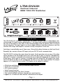
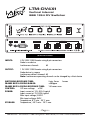
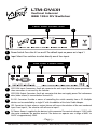
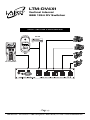
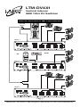
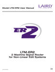
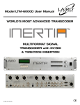
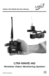
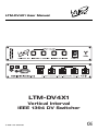
LTM-DV4X1 User Manual
LTM-DV4X1
Vertical Interval
IEEE 1394 DV Switcher
© 2003 Laird Telemedia.
CE
LTM-DV4X1
Vertical Interval
IEEE 1394 DV Switcher
DESCRIPTION
The LTM-DV4X1 DV switcher is a glitch-less DV stream switcher. Up to 4 independent, nonsynchronized, DV inputs can be connected to it. The output will switch on command between
any one of the inputs to any other at the frame boundary with no glitches, that is no extra
nor missing data. The input signals can have widely different time base references and the
switcher will accept and adapt in a manner visually transparent to the user.
Switching is controlled by one of three ways: Manually, by direct buttons on the Front Panel;
Remotely, by a contact closure GPI input; or by an RS-232 serial communication.
The LTM-DV4X1 isolates the output from the inputs. Each input does not see any of the other
inputs nor does it see the output and in turn is not seen by its Host as a device. Consequently,
only the DV stream is switched and commands are not passed through by the output to any
of the inputs. Each input DV stream is assumed to be on channel 63. The output is on channel 63 on power up but can be changed by the Host to any other legal number. The output
appears as a camera device to other 1394 nodes on the output’s network.
FEATURES
• Glitch-free switching of non-synchronized media sources
• Small size, 1U half rack
• GPI Control Interface
• Serial Control Interface
• Quick switching time, less than 3 frames
• Can control multiple switchers through one serial interface
• Appears as a camera to other devices connected to the output
- Page 1 800-898-0759 • 845-339-9555 • 2000 Sterling Road • Mount Marion, NY 12456 • www.lairdtelemedia.com
LTM-DV4X1
Vertical Interval
IEEE 1394 DV Switcher
SPECIFICATIONS
INPUTS:
4 DV IEEE-1394 Firewire using 6-pin connectors
Node is no device
Isochronous channel :
63
OUTPUT:
1 DV IEEE-1394 Firewire using 6-pin connectors
Node device is camera
Isochronous default channel: 63
Note: Isochronous operating channel can be changed by a Host device
SWITCHING RESPONSE TIME:
2min. 3max
frames
FRAME RATE LOCKING RANGE:
±500ppm
FRAME RATE LOCKING RESPONSE TIME:
16 frames max
CONTROL:
GPI max voltage ±10V
POWER:
Input current at 12V, 0.22A typical
Input current at 7V, 0.39A typical
Max input voltage, 24VDC
Min input voltage, 6VDC
Temperature, 0°C min - 55°C max
STORAGE:
Temperature, -20°C min - 70°C max
- Page 2 800-898-0759 • 845-339-9555 • 2000 Sterling Road • Mount Marion, NY 12456 • www.lairdtelemedia.com
LTM-DV4X1
Vertical Interval
IEEE 1394 DV Switcher
FRONT PANEL CONNECTIONS
2
1
1
Power Switch: Turns the 4x1 on or off. The default input on power on is Input 1.
2
Input Select: Four switches to select directly one of four inputs.
REAR PANEL CONNECTIONS
5
4
3
2
1
1
IEEE-1394 Inputs Connectors: One 6-pin connector for each input. Note that power presented in
these connectors is not used by the switcher.
2
IEEE-1394 Output Connector: One 6-pin connector that does not supply power. The isochronous
data (video stream) is transmitted on channel 63
3
RS-232 Connector: Provides a means of controlling the switch remotely from a PC. Multiple
devices can be controlled by a single PC with the addition of the Serial Cable Adapter.
4
GPI Connector: An input where a contact closure will cause the selection of the next numbered
input. From input 4, the selection will roll-over to input 1.
5
DC-Power: Power is supplied to the device via this connector. The nominal voltage is 12VDC with
the center conductor the positive terminal. The device can operate over a range of 6VDC to
24VDC at approximately 2.8W.
- Page 3 800-898-0759 • 845-339-9555 • 2000 Sterling Road • Mount Marion, NY 12456 • www.lairdtelemedia.com
LTM-DV4X1
Vertical Interval
IEEE 1394 DV Switcher
SINGLE SWITCHER CONFIGURATION
DV VTR
YUV
NLE
PC as Controller
- Page 4 800-898-0759 • 845-339-9555 • 2000 Sterling Road • Mount Marion, NY 12456 • www.lairdtelemedia.com
LTM-DV4X1
Vertical Interval
IEEE 1394 DV Switcher
MULTIPLE SWITCHERS IN 10X1 CONFIGURATION
Serial Cable
Adapter
PC as Controller
Switcher 1
DV VTR
NLE
YUV
Switcher 2
Switcher 3
- Page 5 800-898-0759 • 845-339-9555 • 2000 Sterling Road • Mount Marion, NY 12456 • www.lairdtelemedia.com
LTM-DV4X1
Vertical Interval
IEEE 1394 DV Switcher
OPERATION - MANUAL CONTROL
The LTM-DV4X1 can be controlled manually by pressing one of the four pushbutton switches
on the front panel. If a signal is present at the input, the button will light up. If there is no
signal, or the signal is corrupt, then the light will flash and the output will be turned off. The
output will automatically return when the signal has been restored.
In switching between two non-synchronized sources, the phasing or relative timing between
the sources cannot be altered nor can their frequencies or basic frame rates. The LTM-DV4X1
switches between the two sources and automatically adjusts its output frame rate to match
that of the switched input. The consequence of the phasing difference is a variable time delay
between the output and the switched input. The range of time delay is from 0.3 to 1.0 frame.
OPERATION - GPI CONTROL
Closing the contact at the GPI connector will cause the switch to advance the input one count
from 1 to 4 and rolling over back to 1. The equivalent circuit of the input is shown below. The
trailing edge (switching to ground) is detected and the minimum pulse width is 10mS.
OPERATION - RS232 CONTROL
Controlling a Single 4x1 Switch
To control the 4x1 switch by RS232 control, set your serial port control to 8 bits data, no parity, 1 stop bit, and 57,600 bps baud rate. Control is achieved by sending an ASCII character
equal to 1 through 4 to select input 1 through 4 respectively followed by an ASCII carriage
return (CR). The CR character will activate the 4x1 switch. If multiple numbers are sent then
followed by CR, then the last number sent before CR will represent the input chosen.
(continues…)
- Page 6 800-898-0759 • 845-339-9555 • 2000 Sterling Road • Mount Marion, NY 12456 • www.lairdtelemedia.com
LTM-DV4X1
Vertical Interval
IEEE 1394 DV Switcher
OPERATION - RS232 CONTROL
Simultaneous Control of an Arbitrary Number of 4x1 Switches
Set the serial port the same way as for the single switch control. Connect the 4x1 switches
using one serial cable and one Daisy-chain adapter cable for each extra unit to be controlled.
Send a series of numbers between 1 and 4 with each number representing the input desired
for each 4x1 switch followed by the CR. The last number sent will control the 4x1 switch that
is electrically nearest the controller in the Daisy-chain connection, the next to last number will
be for the next to nearest switch and so on. For example, if three 4x1 switches, A B and C, are
connected in the following manner; the control cable goes from the controller to an adapter
and to 4x1 switch A. The next serial cable goes from the adapter at switch A to a second
adapter which is connected to 4x1 switch B. Lastly, a third serial cable connects to 4x1 switch
C. Next, the following sequence of characters are sent:
1 2 3 4 CR
After the controller sends CR, 4x1 switches A, B and C will display as output Input 4, 3 and 2
respectively. The 1 number will have been ignored by all switches as only the last three numbers are remembered in this setup.
In this control protocol, each 4x1 switch keeps for itself the last number received and passes
on to the next stage the previous number received. The CR is always passed on. In the above
example, the controller will receive:
1 CR
This is a way for the controller to tell that there are three 4x1 switches connected to its serial port as four numbers were sent and one number was returned or echoed.
- Page 7 800-898-0759 • 845-339-9555 • 2000 Sterling Road • Mount Marion, NY 12456 • www.lairdtelemedia.com
SAFETY PRECAUTIONS
1. To prevent fire or shock hazard, do not expose this equipment to the environment of
Humidity and/or dust. Do not use this equipment in an unprotected outdoor installation
or any area classified as a wet area.
2. The operating temperature of this product must be kept between -40°C and +95°C.
Direct sunlight or an intense source of heat, direct or ambient, must not be introduced
to the product either by induction or contact.
3. Always keep the product on a stable and secure base or enclosure. Do not drop the
product or subject it to sudden heavy impact.
4. Provide adequate ventilation so that thermal characteristics do not cause an increase in
product temperature to resulting in overheating.
5. Do not clean the unit by using electrically conductive or corrosive chemicals. Always be
certain to unplug the unit from AC wall power before any major cleaning. Use a damp
cloth only for cleaning.
6. Do not subject the product to electrical mains power over voltage: The product must be
used at the rated supply voltages indicated on the product rear panel only.
7. Do not plug the product into an overloaded electrical outlet. This may result in fire or
electrical shock.
8. Object Ingress and Liquid Entry: Never insert or push sharp metal objects into the product
or use such devices for an attempt at opening or servicing the product. Servicing should
be referred to a trained and qualified technician only. Do not allow liquid of any type to
enter the unit. Do not allow the unit to be submersed in water as this may cause a shock
hazard.
9. A trained qualified technician should perform all servicing of the unit. There are no serviceable components within the unit for user access.
- Page 8 800-898-0759 • 845-339-9555 • 2000 Sterling Road • Mount Marion, NY 12456 • www.lairdtelemedia.com
2000 Sterling Road • Box 720
Mount Marion, NY 12456
800-898-0759 • 845-339-9555
Fax: 845-339-0231
www.lairdtelemedia.com