1
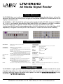
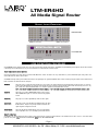
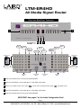
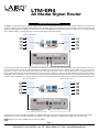
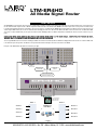
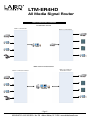
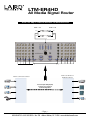
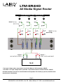
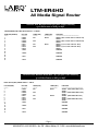
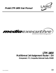
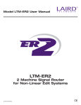
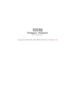
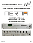
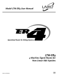
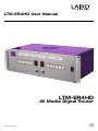
LTM-ER4HD User Manual
LTM-ER4HD
All Media Signal Router
© 2007 Laird Telemedia.
CE
LTM-ER4HD
All Media Signal Router
GENERAL DESCRIPTION
The LTM-ER4HD allows users to switch and control multiple external digital or analog audio-video devices to and from their
destination. This all-format unit not only routes the signals, but also provides full duplex RS422 machine control with the
simplicity of one button control.
The LTM-ER4HD is a 1.0Ghz bandwidth high performance product capable of handling SDI, HDSDI, Component (YPrPb)(R-Y,
B-Y, Y) (YUV) YC and Composite video processing. Digital audio AES/EBU is also supported. A utility port is available to
control other LAIRD devices. The product is housed in a 3RU EIA rack mount unit and works in PAL or NTSC.
As a Non-Linear Edit (NLE) router this unique product provides a 4x1x4 NLE switching function. Select Audio, Video or RS422
independently or all together to and from your NLE. Now with built-in 1:1machine-to-machine override for dubbing.
SPECIFICATIONS
VIDEO BANDWIDTH:
Group A, B: SDI, HDSI, Component, Composite: 1.5Ghz
Group Y/C: 10Mhz
AUDIO BANDWIDTH:
Group AUD: Analog or Digital Compatible: 1Mhz
SWITCHING GROUPS:
INPUT / OUTPUT (I/O):
RS232:
UTILITY:
CONTROL:
DISPLAY:
VIDEO SPECIFICATIONS
VIDEO PERFORMANCE:
Group A: 4 lines of signals @75 ohm Impedance. Can be used for Component (YUV),
Composite Video, SDI
Group B: 1line of signal @75 ohm Impedance. Can be used for SDI, HDSDI and Analog
BANDWIDTH:
RESPONSE:
Measured with a 40 IRE 3.58Mhz sine wave a linear ramp 0-100 IRE
70Mhz unity gain bandwidth
DC - 100Mhz overall
DC - 70Mhz Baseband @ + 0.05dB
TILT:
< 0.5%
OVERSHOOT:
< 0.15%
Group Y/C: 4-pin Din Standard S-Video
Group Audio: 2 channels of Audio using 15Pin Dsub connectors wired for Input and output of each device. 15pin to Male-Female 3pin XLR breakout 6 foot cables
are provided. 4 Device cables and 1 Editor(I/O) cable.
Group 422: 4 standard duplex Sony Machine Protocol RS422 Serial Using 9pin Female
connectors Uses standard 9pin to 9pin RS422 cables: Cables not provided
Each Group switched to a common matching connector (ALL SWITCHING IS PASSIVE)
DC OFFSET:
0V @ 1Vp-p into 75 ohm
ADJ. CROSSTALK:
-65dB tested @ 10Mhz
Special port for controlling other LAIRD devices
AUDIO PERFORMANCE:
External RS232 serial control for remote control operation
Group Select: Enables or disables the groups to switch when the SELECT button is
pressed.
Device Select: Selects rows(device) 1-4: advances one position each press
DUB: Enables DUB mode: Bypasses all I/O connections (devices) and connects 4:1 to
1:4. This allows a simple 1:1 connection between Bank 1 and Bank 2 selected
rows(devices) NOTE: In DUB mode the RS422 I/O is not affected
Input Select (1-4): Seven segment LED display provides readout for input (device selected)
DIFFERENTIAL GAIN:
DIFFERENTIAL PHASE:
AUDIO SPECIFICATIONS
0.01%
0.05%
Measured with 1KHz 1.2Vp-p sine wave (balanced audio)
FREQUENCY RESPONSE: 10-60KHz + 0.1dB
S/N RATIO:
DISTORTION:
85dB, at specified tested center frequency for response
< 0.05%
CROSSTALK:
> 110dB isolation
PHYSICAL SPECIFICATIONS
POWER:
5v DC @ 1.5A via 5-pin XLR AC Adapter: 110/220V AC 50/60 Hz @ .5amps, Automatic Switching
DIMENSIONS: 5.25”H x 9”D x 19”W EIA Rackmount
TECHNICAL SUPPORT
The LTM-ER4HD is a highly specialized, flexible and adaptive product. It would be impossible to include with this manual
all possible wiring solutions. In an effort to provide you with as much information and assistance as possible, we will continually post application diagrams and operator manual updates at our web site: w w w .l a i r d t e l e m e d i a .c o m You may
also E-mail us at i n f o @l a i r d t e l e m e d i a . c o m .
- Page 1 800-898-0759 • 845-339-9555 • Box 720 • Mount Marion, NY 12456 • www.lairdtelemedia.com
LTM-ER4HD
All Media Signal Router
PRODUCT LAYOUT ORIENTATION
Rear Panel View
BANK 1 Connections
BANK 2 Connections
Front Panel View
BANK 2 Control
BANK 1 Control
USER OPERATIONAL PROCEDURES
The LTM-ER4HD has been designed to make its use easy and very functional in all media environments. The ER4HD is a high bandwidth passive backplane switcher with a software
controlled logic front end that allows the easy selection and direction of multi-format Video and Audio signals.
F R O N T PA N E L G R O U P S E L E C T S W I T C H E S :
The front panel switches are positive quiet-touch switches with LED function confirm. The switches are easy to understand once you have studied the layout of the product. Each
switch is labeled for the function that it controls.
The ER4HD is basically a dual 4 position multi-format switcher. The input/outputs are organized in GROUPS which are then selected by front panel switches and an enable function.
Bank 1 and Bank 2 are identical in function and layout.
G R O UP A :
This group is 4 lines of video that switch together. They can be used for any analog signal from Composite Video(CV) to Component video. It can also be
used for regular SDI signals(4). Since all 4 lines switch together, this group is perfect for Component Video with a CV line for monitoring each source. Any
type of video can be fed to the GROUP A BNCs. You can feed 4 separate CV or SDI signals if that is desired.
N O T E : T H I S G R O U P C A N N O T B E U S E D F O R H D S D I S I G N A L S . I T I S TO B E U S E D F O R A N A L O G V I D E O A N D S D I D I G I TA L S I G N A L S O N LY.
G R O UP B :
This group is to be used for DIGITAL VIDEO signals. It can be used for
SDI and HDSDI video signals. It can also be used for analog signals if
needed.
G R O UP Y C:
This group is to be used for 4pin DIN style S-VHS / YC video signals.
G R O UP A UD :
This group is used to select the Balanced or Digital audio via the 15pin
D-Sub breakouts. Study the rear panel layout detail to determine the
signal assignment configuration for audio.
G R O U P R S 4 22 :
This group will switch the RS422 Machine control associated with the
various compatible sources. It is a full duplex passive RS422 switcher.
R E M O T E O P E R AT I O N :
The ER4HD can be operated directly from the front panel or via an optional remote control pad. Optional software is also available to allow a PC to serve as a control device with a
point and shoot system. L O C: puts the ER4 in LOCAL MODE R E M : puts the ER4 in REMOTE MODE.
- Page 2 800-898-0759 • 845-339-9555 • Box 720 • Mount Marion, NY 12456 • www.lairdtelemedia.com
LTM-ER4HD
All Media Signal Router
FRONT AND REAR PANEL FUNCTIONS
E
A
Audio 4
Group A
Bank 2
Group B
Bank 2
Group YC
Bank 2
Audio 3
B
Audio
1 / 2
D
C
Audio I/O
Bank 1&2
Audio
3 / 4
Group YC
Bank 1
Group B
Bank 1
Group A
Bank 1
Input Select 1-4
Bank 1
Input Select 1-4
Bank 2
Video I/O
Bank 2
Video I/O
Bank 1
Group 422
Bank 2
Group 422 I/O
Bank 2
A Group Select Switches Bank 1: Selects groups A,B,YC,AUD,RS422
B
Group 422 I/O
Bank 1
Group 422
Bank 1
Input Select Switch Bank 1: Selects signal inputs 1-4. LED display selected input
C Remote / Local Switch: Selects control source: R E M - remote control via optional remote panel. L O C - front panel control
D Input Select Switch Bank 2: Selects signal inputs 1-4. LED display selected input
E Group Select Switches Bank 2: Selects groups A,B,YC,AUD,RS422
IMPORTANT: See pages 7 & 8 for Audio Configuration Detail
- Page 3 800-898-0759 • 845-339-9555 • Box 720 • Mount Marion, NY 12456 • www.lairdtelemedia.com
LTM-ER4
All Media Signal Router
SPECIAL RS422 MODE
The ER4HD has a special feature which is very handy when using a single NLE system and multiple RS422 controlled devices. The Video and Audio wiring of this type of system is fairly simple to understand. The source A/V signals (capture) should be wired to the BANK 1 connections for each device. Then the I/O for that bank is connected to the input of the NLE.
Likewise the output A/V signals of the NLE will be connected to the I/O connections of the ER4HD Bank 2 section(1x4). The inputs of the recording devices can now be wired to the different “OUTPUTS” of Bank 2. See the diagram below for clarity: Note that this diagram shows the A/V wiring only.
Bank 2 as 1x4 Switcher
Bank 1 as 4x1Switcher
AV I / O
AV I / O
Non-Linear Edit System
A/V
This switch selects
source devices for capturing
A/V
This switch selects
destination devices for recording
Now, the fact is that the NLE only has one common port for RS422 and each device needs to be in contact with the NLE during the ingest or capture phase where Bank 1 is being used.
At this point the RS422 cables connected o the Bank 1 RS422 9pin ports are switched as you select the various devices for capturing footage into the NLE. Now once you are done editing your project, you want to transfer edited footage back to any of the various devices (VTRs) that are still connected. Now Bank 2 which is wired as a 1x4 assignment switcher can
take care of the A/V signals in this mode where the NLE output is selected to feed a particular recording device. In this mode the RS422 is still being controlled by the Bank 1 switches.
The ER4HD has a feature which allows the control of the RS422 still connected to Bank1 selector switch(1-4) with the Bank 2 selector(1-4) switch. This makes the RS422 follow the NLE
to Recorder selection switch(pushbutton 1-4) on Bank 2. This is very convenient so that you still can perform a single button machine control function for both A/V and RS422 functions.
Bank 2 as 1x4 Switcher
Bank 1 as 4x1Switcher
RS422 I/O
RS422
AV I / O
Non-Linear Edit System
RS422 switching is controlled
by this selector switch
Note: Display shows ʻzeroʼ in this mode
A/V
This switch selects
destination devices for recording
To enable this function simply press the RS422 and SELECT button of BANK1 simultaneously. The display above the SELECT button will display ZERO and the RS422 LED of BANK 1
will illuminate. Now as you press the BANK 2 SELECT buttons the RS422 connected to BANK 1 will follow. To disable this feature, simply press the same buttons again.
N O T E : During this mode of operation, all BANK 1 A/V select switches are disabled.
- Page 4 800-898-0759 • 845-339-9555 • Box 720 • Mount Marion, NY 12456 • www.lairdtelemedia.com
LTM-ER4HD
All Media Signal Router
DUB FEATURE
The LTM-ER4HD has a special feature where the system is configured where an NLE for example is the designation and return device. The example would be where 4 source VTRs are fed
into the 4x1 bank and the output is fed into a NLE. The output of the NLE is then fed to the 1x4 Bank of the ER4HD. In this mode it may become necessary to make a machine(source)
to machine dub and BYPASS the NLE. To avoid having to disconnect any devices to accomplish this, the ER4HD simply internally bypasses the NLE I/O and connects the 4x1 I/O to the
1x4 I/O. Using the DUB switches, the user can now enable this mode and simply select the source OUT on the 4x1 Bank and it will be connected to the IN on the 1x4 Bank and the DUB
can be done. To enable the DUB mode you must press both switches and the LED display will show a ZERO in both Banks. In the DUB mode all of the selected 1-4 devices are operational.
N O T E : I N D U B M O D E G R O U P B ( D I G I TA L ) W I L L O N LY A L L O W D U B B I N G F R O M D E V I CE 1 -3 F O R H D S D I S I G N A L S . I N P U T #4 W I L L N O T F U N CT I O N I N H D S D I .
H O W E V E R F U L L 1 -4 D E V I C E D U B I N G W I L L F U N C T I O N F O R S D I D E V I C E I N P U T S E L E C T I O N .
Once the signal GROUPS have been selected for switching, the INPUT select switches located directly under the LED numeric display will allow the selection of 1-4 devices. BANK 1 and
2 are identical in layout and operation. The ER4 has a memory which will remember which input 1-4 has been selected for each GROUP.
Each push of the SELECT button will advance the selection by one digit.
Group 422
Bank 2
Group 422
Bank 1
Remote / PC
Utility Port for Control
Serial Port
of Laird Products
5V DC Power / 1.5A Regulated
5-pin XLR: Pin2 - GND, Pin3 - 5V
Dub Feature
Source 1
Source 2
Source 3
Source 4
Bank 1
Press both dub buttons
to engage Dub Mode.
LED reads Zero-Zero
NLE Bypass
Dub Mode
NLE
Bank 2
Record 1
Record 2
Record 3
Record 4
- Page 5 800-898-0759 • 845-339-9555 • Box 720 • Mount Marion, NY 12456 • www.lairdtelemedia.com
LTM-ER4HD
All Media Signal Router
BASIC OPERATIONAL DIAGRAMS
Bank 1 as 4x1Switcher
TWO INDEPENDENT SWITCHERS
NLE AS CORE
IN
4X1X4 CONFIGURATION
Bank 1 as 4x1Source Selector
Bank 2 as 1x4 Switcher
Bank 2 as 1x4 Record
Destination Selector
- Page 6 800-898-0759 • 845-339-9555 • Box 720 • Mount Marion, NY 12456 • www.lairdtelemedia.com
LTM-ER4HD
All Media Signal Router
USING THE ER4 AS A MASTER MACHINE TO MACHINE ROUTER
BANK 1 I/O
BANK 2 I/O
Ch1
Ch1
Ch2
Ch2
Bank 2 as 1x4 Record
Destination Selector
Bank 1 as 4x1Source Selector
Connect Input / Output (I/O)
Connectors to Create a
4x1x4 Configuration
- Page 7 800-898-0759 • 845-339-9555 • Box 720 • Mount Marion, NY 12456 • www.lairdtelemedia.com
LTM-ER4HD
All Media Signal Router
(VTR)
1
BANK 2 (1-4)
AUDIO BREAKOUT CABLE CONFIGURATION
(VTR)
Ch1
3
Ch1
Ch2
(VTR)
4
Ch1
Ch1
Ch2
Ch2
Ch2
Ch1
Ch1
Ch1
Ch1
Ch2
Ch2
Ch2
Ch2
*
Ch1
**
OUT
NLE
IN
Ch1
NLE OUTPUT to VTR 1-4
*
Ch2
BANK 2
*
Ch2
*
(VTR)
2
BANK 1 (1-4)
BANK 1
VTR 1-4 OUT to NLE INPUT
* Four Input / Output cables are provided: 15-pin D-Sub Male to 4 XLR connectors (2M)(2F)
** One Bank 1 & 2 Input / Output cable is provided: 15-pin D-Sub Female to 4 XLR connectors (2M)(2F)
All audio connectors are wired in standard balanced configuration. All switching is passive, therefore audio
may be wired bi-directionally.
- Page 8 800-898-0759 • 845-339-9555 • Box 720 • Mount Marion, NY 12456 • www.lairdtelemedia.com
LTM-ER4HD
All Media Signal Router
TECHNICAL DATA: BALANCED AUDIO I/O (FOUR CABLES PROVIDED)
15 PIN D-SUB MALE TO XLR 3 PIN M/F
SOURCE MEDIA(VTR) CABLE INPUT-OUTPUT : 4 CABLES
D15M PIN#(SOURCE)
--------1
2
3
4
5
6
7
8
9
10
11
12
13
14
15
PIN# XLR
------------2 XLM 1
3 XLM 1
2 XLM 2
3 XLM 2
2 XLF 1
3 XLF 1
2 XLF 2
3 XLF 2
1 XLM 1
LABEL(XLR)
---------CH1
LABEL(CBL)
----------------Bank 2
CH1
Bank 1
CH2
CH2
1 XLM 2
FUNCTION
----------------------------------------------------AUDIO + (Record Audio OUT to VTR CH1 -IN)
AUDIO AUDIO + (Record Audio OUT to VTR CH2 -IN)
AUDIO AUDIO + (Source Audio VTR CH1 -OUT)
AUDIO AUDIO + (Source Audio VTR CH2 -OUT)
AUDIO GROUND
GROUND
1 XLF 1
GROUND
1 XLF 2
GROUND
TECHNICAL DATA: BALANCED AUDIO BANK 1 & 2 I/O (ONE CABLE PROVIDED)
15 PIN D-SUB FEMALE TO XLR 3 PIN M/F
INPUT-OUTPUT(NLE) MEDIA CABLE : 1 CABLE
D15F PIN#(NLE)
--------1
2
3
4
5
6
7
8
9
10
11
12
13
14
15
PIN# XLR
------------2 XLM 1
3 XLM 1
2 XLM 2
3 XLM 2
2 XLF 1
3 XLF 1
2 XLF 2
3 XLF 2
1 XLM 1
LABEL(XLR)
---------CH1
LABEL(CBL)
----------------Bank1
CH1
Bank2
CH2
CH2
1 XLM 2
FUNCTION
------------------------------------------------AUDIO+ (TO NLE AUD INPUT CH1)
AUDIO AUDIO + (TO NLE AUD INPUT CH2)
AUDIO AUDIO+ (TO NLE AUD OUT CH1)
AUDIO AUDIO + (TO NLE AUD OUT CH2)
AUDIO GROUND
GROUND
1 XLF 1
GROUND
1 XLF 2
GROUND
- Page 9 800-898-0759 • 845-339-9555 • Box 720 • Mount Marion, NY 12456 • www.lairdtelemedia.com
LTM-ER4HD
All Media Signal Router
Safety Precautions
1. To prevent fire or shock hazard, do not expose this equipment to the environment of Humidity and/or dust. Do not use
this equipment in an unprotected outdoor installation or any area classified as a wet area.
2. The operating temperature of this product must be kept between -40°C and +95°C. Direct sunlight or an intense source
of heat, direct or ambient, must not be introduced to the product either by induction or contact.
3. Always keep the product on a stable and secure base or enclosure. Do not drop the product or subject it to sudden heavy
impact.
4. Provide adequate ventilation so that thermal characteristics do not cause an increase in product temperature to resulting in overheating.
5. Do not clean the unit by using electrically conductive or corrosive chemicals. Always be certain to unplug the unit from
AC wall power before any major cleaning. Use a damp cloth only for cleaning.
6. Do not subject the product to electrical mains power over voltage: The product must be used at the rated supply voltages indicated on the product rear panel only.
7. Do not plug the product into an overloaded electrical outlet. This may result in fire or electrical shock.
8. Object Ingress and Liquid Entry: Never insert or push sharp metal objects into the product or use such devices for an
attempt at opening or servicing the product. Servicing should be referred to a trained and qualified technician only. Do
not allow liquid of any type to enter the unit. Do not allow the unit to be submersed in water as this may cause a shock
hazard.
9. A trained qualified technician should perform all servicing of the unit. There are no serviceable components within the
unit for user access.
- Page 10 800-898-0759 • 845-339-9555 • Box 720 • Mount Marion, NY 12456 • www.lairdtelemedia.com
Box 720
Mount Marion, NY 12456
800-898-0759 • 845-339-9555
Fax: 845-339-0231
www.lairdtelemedia.com