1
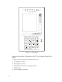
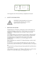
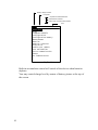
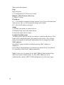
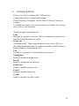
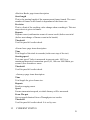
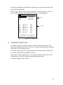
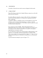
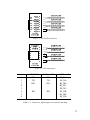
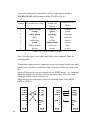
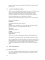
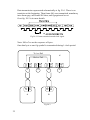
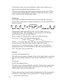
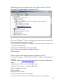
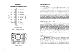
TECHNICAL DESCRIPTION
AND
USER MANUAL
ETHERNET TESTER
ATLAN
CONTENTS
1
INTRODUCTION .................................................................................... 4
2
OPERATING CONDITIONS................................................................. 4
3
TECHNICAL PARAMETERS............................................................... 4
4
SUPPLY CONTENTS ............................................................................. 6
5
CONSTRUCTION AND PRINCIPLES OF OPERATION ................ 7
5.1 DEVICE CONSTRUCTION ........................................................................... 7
6
SAFETY INFORMATION ..................................................................... 9
7
PREPARE FOR WORK ......................................................................... 9
8
GETTING STARTED ........................................................................... 11
8.1 MAIN MENU ........................................................................................... 11
8.2 MAIN MENU FUNCTIONS LIST ................................................................. 11
9
INTERFACE SETUP ............................................................................ 13
10
PING ...................................................................................................... 15
11
LOOPBACK-MODULE...................................................................... 17
12
CONFIGURATION .............................................................................. 19
13
CURRENT STATUS............................................................................ 21
14
RESULTS.............................................................................................. 22
15
REPORTS CREATION ...................................................................... 23
16
STATISTICS ........................................................................................ 26
17
CABLE TEST ....................................................................................... 26
18
SFP INFORMATION .......................................................................... 29
19
VOICE COMMUNICATION............................................................. 30
20
MEASUREMENTS.............................................................................. 30
20.1 ETHERNET BASICS ................................................................................ 30
20.2 GET STARTED ....................................................................................... 34
20.3 ALARMS AND EVENTS INDICATORS ...................................................... 39
2
21
COMMUNICATION WITH PC ........................................................ 40
22
SETUP ................................................................................................... 40
23
FIRMWARE UPDATE ....................................................................... 40
24
STORAGE AND TRANSPORTATION............................................ 42
25
WARRANTY ........................................................................................ 42
26
DEVICE SERIAL NUMBER.............................................................. 43
3
1
INTRODUCTION
Network tester «ATLAN» provides performance analysis of various
network equipment or network segments for data transmission
compatible with Ethernet technology.
The device is best to use when building, setting, and maintaining
network infrastructure. It is especially useful when high bandwidth and
latency critical services are deployed such as IPTV, video on demand,
and so on.
«ATLAN» provides:
• Testing according to RFC 2544 methodology with direct connection
to copper or optical Ethernet interface.
• Testing over others technologies, that using Ethernet standards for
equipment connection (xDSL, WiFi, etc.)
• IP Delay Variation (Frame jitter) according to RFC 3393
• Standard testing utilities (ping)
• Copper cable fault detector
• Simple voice communication between devices
• Reports creation
2
OPERATING CONDITIONS
• Ambient temperature
• Relative air humidity
• Atmospheric pressure
3
−20 ÷ +50 oC
up to 90 % at 30 oC
86 ÷ 106 kPa
TECHNICAL PARAMETERS
Device power source is four AA NiMh accumulator batteries 1.2 V with
2,3 А/H capacity. This provides about 4 hours of operation (actual time
depends on link speed, optical module type and screen brightness).
External 220V AC to 12V DC adapter is used to charge accumulators as
well as device powering.
4
Frame size (bytes)
According to RFC2544
VLAN Support
Cable tests
(copper interface 8P8C connector)
Cable length estimation
Copper (8P8C, RG45)
Optical
Duplex
64, 128, 256, 512, 1024, 1280,
1518
custom
Levels 1 and 2 (QinQ)
Open, short, impedance
mismatching,
Distance to defect estimation
Copper interface in 1000
Mbit/s mode
10 Mbit/s
100 Mbit/s
1000 Mbit/s
SFP module
1000 Mbit/s
full
5
4
6
SUPPLY CONTENTS
№
Наименование
Кол-во
1
ATLAN
1
2
Power adapter 12 V
1
3
Patchcord 5e cat.
1
4
User Manual
1
5
PC CD with user manual
and driver software
1
6
Soft case
1
7
PC USB cable
1
Примечание
5
CONSTRUCTION AND PRINCIPLES OF OPERATION
5.1 Device construction
Device enclosed in aluminum shock resistant case.
On the front panel of the device (fig. 5-1), are located:
• Alarms and events indicators
• Graphic LCD display with backlight
• Power button
• Functional buttons F1, F2, F3, F4
• Navigation buttons: «left», «right», «up», «down», «Ok», «Esc»
• Instant switch to control mode button
• Fast menu pages switching buttons P+ и P• Additional buttons: M1, M2
• Charge process indicator (red), Power indicator (green)
7
Laser
Link
Loop
Test
Error
Result
Event1
Event2
ATLAN
F1
F2
F3
F4
1 abc
2 def
3 ghi
4 jkl
6 pqr
7 stu
P+
5 mno
M1
8 vwx
P9 yz
0 -+/
M2
Bsp
Esc
Ok
Figure 5-1. Front panel
On the sockets panel of the device (fig. 5-2) are located (from left to
right) :
• SFP socket for optical module connection
• Headphones socket
• Microphone socket
• 8P8C (RG-45) socket for copper cable
• USB socket
• Power supply connector
8
USB
12V
SFP
Fig 5-2. Sockets panel
At the opposite side of the case battery compartment is located.
6
SAFETY INFORMATION
WARNING! Optical modules are the sources
of invisible laser radiation. Do not direct
optical sockets in eyes or face.
7
PREPARE FOR WORK
Unpack the device. Perform a visual check, ensure in the absence of
mechanical damages on the device. If the devices were stored at low
temperatures or high humidity, dry it during 24 hours at normal
conditions.
Four NiMh elements are used as device power source. When external
power supply is connected, device is switched to this external source
and charge process (if required) has also started. After charge
completition device continue to use external supply until it is
disconnected.
New accumulators are required 6-10 charge-discharge cycles to reach
full capacity.
Turn the device on by pressing ON/OFF button two times first time for short time, and second time press it and hold until device will power
up.
To turn the device off press the same button and hold it until the device
will shut down.
After startup screen appear on LCD press (Ok) button or wait for a few
seconds. As a result main menu will be displayed (fig. 7-1).
9
Battery voltage indicator
Link speed
Duplicate IP address detected
Measurement indicator
Active voice communication indicator
Time
1G
!MV
12:00:05
Interface
Ping
Loopback-module
Configuration
Configuration Memory
Measurement
Results
Reports creation
Statistics
Cable test (RG45)
SFP Information
Voice communication
Setup
PC communication
Fig 7-1. Main menu
Built-in accumulator control will switch of the device when batteries
depletes.
You may control charge level by means of battery picture at the top of
the screen.
10
8
GETTING STARTED
8.1 Main menu
The device provides a set of functions which can be accessed through
main menu.
Main menu is composed of pages and every page is composed of items.
Items are displayed in the form of a list.
Using «È» и «Ç» buttons you may change active item, which is
marked by color inversion.
By pressing «Ok» button you may enter into item, and return back to
main menu by pressing «Esc».
Most of main menu items have it’s own menus organized into one ore
more pages (tabs). To select desired page use «Page» item or use
buttons «P+» - next page и «P-» - previous page.
On menu pages there are lists of various parameters.
With help of «È» и «Ç» buttons you may change selected parameter,
which is marked with test inversion. Using functional buttons and «Å»,
«Æ» and «Ok» buttons current parameter value can be changed.
8.2 Main menu functions list
Interface
Set up device at physical and communication level
Ping
Send and receive echo requests using ICMP (Internet Control Message
Protocol)
Loopback module
Discovery and setup loopback module operation
Configuration
Setting up test parameters
Configuration memory
Save and load interface parameters and test parameters.
Measurement
Start and stop measurements, progress information, test results in short.
Results
View test results.
Report creation
Test report creation using current test results.
11
Statistics
Various frame reception statistics.
Cable Test (RG45)
Provides copper cable tests
SFP information
Getting built-in SFP module information
Voice communication
Establish voice communication channel between two ATLAN devices.
Setup
Setup date, time and some other functions.
PC communication
Communicate with PC for generated report.
To enter to some items you need to stop current measurement process.
12
9
INTERFACE SETUP
1G
12:00:05
Page
Тип:
Mode:
Autoneg:
Speed:
Duplex:
Flow Control:
Port
copper
Auto (MDI)
On
1000Mbit
Full
Off
F1.Port
F2.Network
F3.VLAN
Current button action
F1, F2, F3, F4
Рисунок 9-1. Меню настройки линейного интерфейса
Use buttons «È» и «Ç» to change current active item which is
correspond to some parameter. At the bottom of the screen the list of
possible actions or selection variants are displayed.
For example, pressing F2 button will change active page for network
setup.
In some cases full list of variants has more than for items. In this case F4
button is used to view all other values, which will be displayed in
groups of three values after every press of F4 button.
Page
Page selection:
F1-port setup
F2-network setup
F3-VLAN setup
Type
Interface type selection:
F1-copper или F2-optical
Mode
Built-in crossover mode selection for copper cable. This allows use both
«straight» and «crossed» patch cord types for device connection to
13
active network equipment.
Auto mode is recommended.
Autoneg
Autonegotiation and autodetection mode control.
Recommended value is On.
Speed
Maximum speed limit (when autonegotiation is enabled).
Duplex
Current duplex mode – always enabled
Flow control
F1-incoming «Pause» frames are ignored.
F2- incoming «Pause» frames are received; transmitter makes a pause
according to request.
Network page
MAC address
ATLAN is a standard Ethernet device. To set MAC address use
functional keys.
IP address
To set IP address, enter into edit mode and use numeric keys and cursor
keys. You also may select address from the list of last used addresses.
Subnet mask
This mask will be used when creating broadcast request for other
devices discovery. All requests outside subnet are directed to default
gateway.
Gateway
Allows or prohibits gateway use.
Gateway address
IP address gateway. All requests to devices located outside subnet will
be sent to this address.
VLAN page
VLAN lev
VLAN support level:
Off – no support of virtual network,
14
1 – VLAN with one tag (802.1Q standard) VLAN1 fields settings are
used,
2 – VLAN with double tagging (QinQ), VLAN2 is outside tag (located
close to MAC address), а VLAN1 inside tag.
VLAN1
ID type for VLAN1. Possible values are "8100", "88A8", "9100",
"9200", "9300". It is possible to support additional not standard types.
VLAN1 priority
3-bit priority field according to 802.1p.
VLAN1 id
Virtual network number.
VLAN2
ID type for VLAN 2. Possible values are "8100", "88A8", "9100",
"9200", "9300". It is possible to support additional not standard types.
VLAN2 priority
3-bit priority field according to 802.1p.
VLAN2 id
Virtual network number.
10
PING
Ping is a standard utility to test networks.
It is built on the ICMP protocol (Internet Control Message Protocol)
ATLAN is capable receive and handle ICMP requests.
To starts rending requests setup utility parameters at page
«Configuration», set the cursor at menu item «Start» and press «F1»
button. Page results must appear on the screen automatically.
It is possible to return to configuration page by pressing key «P+».
Results are displayed in the form of the table.
Note: Internal MCU is a low speed device, so ping reply time are
relative to it’s speed, therefore this time can not be used as a latency test
result. This is due to relatively low ICMP request processing.
To measure the precise value of latency use test RFC-2544 «Latency».
IP address:
F1. – To set IP address, enter into edit mode and use numeric keys and
cursor keys.
15
F4. – Press this button to select address from the list of last used
addresses.
Data
ICMP frame data field size.
Timeout
It is a time the device awaits the reply in milliseconds.
Use numeric buttons to change current value. Press Ok when done. You
can use «Å» и «Æ» buttons to change active digit.
Interval
Requests send interval in milliseconds.
TTL
Time To Live ICMP frame parameter.
16
11
LOOPBACK-MODULE
To perform RFC-2544 tests two ATLAN devices are required. One of
the devices is a sender of the measurement frames, the second device
make up a loop. It receives frames at the far end of the network and
sends them back to the sender. Any ATLAN device is capable to work
as a master sender or as a loopback-module.
Aneg
12:00:05
Page
Config
Discovery
IP address:
192.168.0.100
Status
unknown
Loopback name
МАС address:
no link
F1.Config
F2.Discov
Fig 11-1. Loopback module setup
The menu of «loopback-module» is composed of to two pages:
configuration and discovery results.
There are several ways to setup the loopback module for testing:
• Enter known device IP-address прибора and set the device to mode
«Loop», if it is not in this mode already (see current remote device
state in the menu item «Status »).
• Perform the discovery operation of ATLAN devices into current
subnet. (The device will use subnet mask to generate a broadcast
request, see interface setup, network)
• It is possible to enable or disable «loopback» at remote device by
manual. See item «Loopback» in the menu «Setup» of main menu.
17
Menu items description:
Page
Page selection:
F1-Configuration, F2-Discovery results
Remote ATLAN devices discovery
F1-Start, F2-Stop
IP address:
F1. – Use numeric buttons to change current value. Press Ok when done.
You can use «Å» и «Æ» buttons to change active digit
F4. – Hot list IP address selection
Status
F1-Enable loop mode on remote device
F2-Disable loop mode on remote device
F4-refresh remote device status
Loopback module name
To make work a little bit easier you can give a name to the device. This
name will be displayed when you connect to this device. See «Setup»
menu description for additional information how to change this name.
MAC address
Here MAC remote module or default gateway MAC address is
displayed.
Error will be displayed here if connection to remote device was failed.
It is possible to enter MAC address manually.
Note: In the case of remote device MAC address detection and loop
mode invocation without errors, its IP и MAC addresses were
automatically copied to RFC-2544 configuration (at «Stream» page).
18
12
CONFIGURATION
This item is used to configure RFC-2544 tests set.
Configuration menu is composed of 6 pages:
General, Stream, Throughput, B-to-B (Back-To-Back), Frame loss,
Latency.
To change active page you can use menu item «Config» (its is always
first) or «P+» и «P-» buttons.
«General» page items description
Units
Megabits per second or percents (100% is a transmission speed set in
interface setup, if another not noted)
Frame size
According to RFC-2544 recommendation or user select. (This is a
physically transmitted frame size without preamble and SFD (Start of
Frame Delimiter), but including CRC.
User
Frame size is given by user (used with previous item)
Throughput
Enable or disable throughput test.
B-to-B
Enable or disable back to back test.
Frame loss
Enable or disable frame loss test.
Latency
Enable or disable latency test.
Verdict
Enable or disable Pass/Fail verdict.
19
«Stream» page items description
IP address:
Loopback module address (another ATLAN device in loopback mode).
Measurement stream destination address.
F1. – Use numeric buttons to change current value. Press Ok when done.
You can use «Å» и «Æ» buttons to change active digit
F4. – Hot list IP address selection
If you set remote device into loopback mode this field will be filled
automatically.
TTL
IP header Time To Live parameter in measurement frame.
TTL/DS
Type Of Service / Differentiated service parameter in measurement
frame.
Precedence
This field is used when setting TOS/DS bits
Source UDP
Use it to set outgoing port (UDP header if measurement frame).
Dest UDP
Use it to set incoming port (UDP header if measurement frame).
MAC address:
Remote device or default gateway MAC address is displayed here.
Error will be displayed here if connection to remote device was failed.
It is possible to enter MAC address manually.
«Throughput» page items description
Time
Trial length in seconds
Precision
Throughput test stop criteria.
Repeats
Repeats count in every trial.
Start speed
Search start speed. It is used to speedup measurements (especially in the
case of low resulting values)
Threshold
Used for pass/fail verdict check.
20
«Back-to-Back» page items description
Start length
This is the starting length of the measurement frames bunch. The exact
number of frames in the bunch is dependant of the frame size.
Precision
This is a limit of the resulting value change when searching it. This test
stop criteria is given in frames.
Repeats
Repeats count (confirmation count of current result) before next trial
(before next change of frames count in the bunch).
Threshold
Used for pass/fail verdict check.
«Frame loss» page items description
Time
Trial length of the trials in seconds (in the next step of the test)
Starting speed
Test start speed. Value is measured in percent units. 100% is a
maximum theoretical connection speed (10, 100 или 1000 Mbits per
second.) See «Interface» menu.
Threshold
Used for pass/fail verdict check.
«Latency» page items description
Time
Trial length for given frame size.
Repeats
Result averaging count.
Speed
Frames transmission speed, at which latency will be measured.
From Thr-put
Set test speed obtained from «Throughput» test results.
Threshold
Used for pass/fail verdict check. It is set by user.
13
CURRENT STATUS
21
Use «Start/Stop» button to quickly enter this mode. This mode is used
for measurement process control.
1G
12:00:00
Tput
B2B
FLos
Lat
M
12:00:05
00:00:05
complete
in progress
in order
in order
Time
yes
rep 1
1689189
128
TX 1689189 RX 1689189
Test progress
Current test
information
Start/Stop
Control menu
F1.Start
F2.Stop
Fig 13-1. Status menu
At the top of the screen test start time and test duration are displayed.
At the middle of the screen test progress is displayed. Behind short test
name, its status is displayed (in order, in progress, complete, aborted)
and result for pass/fail verdict test (yes or no).
Current test progress is displayed (current test frame, transmitted and
received frame count, current repeat number)
At the bottom of the screen menu is located.
Start/Stop
F1 – test start. F2 – test stop.
14
RESULTS
This mode is used for current measurement results display.
Its menu is composed of five pages: Throughput, B-to-B, Frame loss,
Latency and Jitter. Measurement results and pass/fail verdict are
displayed on those pages. Pages switching is performed by means of P+
and P- buttons.
Results are displayed in the form of the table. First column is a frame
size. The second – measurement result in selected units (see.
Measurement settings) and pass/fail verdict result (if it is enabled). You
22
may freely change threshold before and after test, pass/fail results were
reviewed automatically.
There is the «Step» item on page Frame loss. Use this item to view all
the available results (measurements with various throughputs).
1G
12:00:05
Results:
Status
Time
64
128
256
512
1024
1280
1518
Throughput
complete
00:01:25
100.0
100.0
100.0
100.0
100.0
100.0
100.0
%
%
%
%
%
%
%
yes
yes
yes
yes
yes
yes
yes
Menu
Results
F1.Throughput F3.Frame loss
F4.Latency
F2.B-to-B
Figure 16-1. Results menu
15
REPORTS CREATION
To make a report you must complete current measurement first. The
enter file name for report file your save. Create a report with given name
with help of the first menu item.
Use main menu item «PC communication» to transfer report files to PC.
Use Erase when built-in flash disc fills up.
In the case of error appearance, try to copy available report files to PC
and perform a full erase using corresponding menu item.
A report example is given here.
23
24
25
16
STATISTICS
A number of detected errors and events are displayed in this mode.
17
CABLE TEST
The ATLAN device has built-in Gigabit Ethernet transceiver with cable
fault detection functions.
In modern Ethernet networks a copper cable with four twisted pairs is
used a transmission medium. It is connected to equipment with 8P8C
8P8C connectors.
At speeds 10 Mbit/s и 100 Mbit/s only two twisted pairs are used. One
of them is used to transmit data from device 1 to device 2, and the
second one in reverse direction. In 1000 Mbit/s mode four pairs are used
for bidirectional transmission.
Every transceiver has and MDI – Media Dependent Interface. A
differential transceiver is used for copper connection. It is connected to
twisted pair of wires. Built-in transceivers are capable select proper
signal polarity in automatic manner.
It is not allowed to connect wires which belong to different pairs to one
transceiver. It will lead to link fault (impossible to establish a link)
There is an example of wrong connection on figure 17.1. Taps 3 и 6 are
related with one transceiver and must be connected to one twisted pair
of wires.
A good connection example is given in figure 17-2.
26
Fig 17-1. INVALID connection.
Fig 17-2. Valid connection.
contact
1
2
3
4
5
6
7
8
10BASE-T
TD+
TDRD+
100Base-TX
TD+
TDRD+
RD-
RD-
1000Base-T
BI_DA+
BI_DABI_DB+
BI_DC+
BI_DCBI_DBBI_DD+
BI_DD-
Table 17-1. Transceiver input/outputs to connector matching.
27
At present moment the main 8P8C socket connection standard is
TIA/EIA-568-B, which replaced older TIA/EIA-568-А.
contact
First end wire color
1
2
3
4
5
6
7
8
white-orange
orange
white-green
blue
white-blue
green
White-brown
brown
Crossover for
10 and 100
Mbit/s
w/green
green
w/orange
blue
w/blue
оранжевый
w/brown
brown
Crossover 1000
Mbit/s
w/green
green
w/orange
w/brown
brown
orange
blue
w/blue
Table 17-2. Crossover cables (T568B).
Note! Do not forget, your cable may differ from standard. Pairs are
exchangeable.
Transmitter output must be connected to receiver input. In this case only
transceivers are able to establish a link. Crossover cables are used to do
this.
Most of Ethernet devices are capable to use MDIX mode – i.e. exchange
input and output taps on their sockets, therefore they will work with
«straight» cable as well «crossover».
Many devices use automatic crossover selection mode Auto-MDIX
(MDI or MDIX).
28
Рисунок 17-3. Left – both devices are in MDI mode and connected with crossover
cable. Right – straight cable connection, right device is into MDIX mode.
To start the cable test enter the mode, set cursor at «Test» menu item.
Then press «F1» button - Start. Move cursor to menu item «Page» and
use functional keys (F1, F2, F3) to view test results. Test is performed
for every pair (they named MDI0, MDI1, MDI2 и MDI3) in parentheses
standard tap numbers for corresponding pairs are given.
An example view of result screen is at figure 17-4.
LDown
12:00:05
Page:
Test
Results
MDI0(1-2): OK
length: unknown
MDI1(3-6): not matched
at dist: 0 м
MDI2(4-5): open
at dist: 0 м
MDI3(7-8): OK
length: unknown
F1.Results
F2.Addon.
F3.Info
Fig 17-4.
Cable length measurement for good pairs with additional parameters
establishing is performed at speed 1000 Mbit/s only. Link must be
established also. At figure 17-4 you may note the absence of length
value for pairs MDI0 и MDI3. It is because link is down.
MDI1 results denote impedance mismatching. Distance to this
mismatching is very short. This is likely to be impairment (using wires
from different pairs).
At speeds 10 и 100 Mbit/s a standard Time Domain Reflectometry
(TDR) is used for distance to defect detection. Cable length can be
determined by remote end cable disconnection. Do use more advanced
DSP method it is impossible to establish a link at 1000 Mbit/s mode.
18
SFP INFORMATION
This mode is used for reading values from embedded nonvolatile
memory of the module. Read is done automatically when module is
29
plugged. Please contact us if special field reading is required (optical
power for ex.).
19
VOICE COMMUNICATION
There is a voice communication function between two ATLAN devices.
Note: This function automatically disables loopback mode. This
function use simple UDP frames for voice transmission. Signal
buffering is minimal, so into networks with large frame losses and
frames reordering some voice distortions are possible.
Measurement IP and UDP settings are used for voice communication.
Menu items description
IP address
Communication partner device address.
Signal
Possible values – Disabled, tone signal 1000 Hz, microphone signal.
(We recommend use tone signal for headset check).
Mic sense.
Microphone sensitivity
Volume
Earphones volume setting
MAC address
MAC resolve result. Default gateway address can be displayed here.
To establish voice communication, enter IP address and select signal
type. A request will be sent to this address. If remote device receive it, a
sound signal will be issued for operator (three short beeps). IP address
field will be filled with request sender address automatically. To
establish communication far end device user must also select signal
type.
20
MEASUREMENTS
20.1 Ethernet basics
Let’s try to understand Ethernet networks basics. Some details were
reduced intentionally. A detailed description you may find in IEEE
802.3 standards set.
30
Tx
F
Cable
F
F
Rx
Tx
Rx
Each Ethernet networks compatible device has one or more transceivers
(transmitter + receiver, Tx and Rx – in short).
Data transmission is performed over cable line (copper or optical fiber)
in the form of byte stream (i.e. serial transmission). One byte is an
information measurement unit equal to 8 (eight) bits). One bit is a
smallest possible information unit.
Bytes are transmitted with defined speed. This speed sets the theoretical
speed limit of data transmission system. For example, at link speed of
1000 Mbits/s one data byte is transmitted for T=8 nanoseconds (1 ns it is
a one million part of a second).
Every byte transmission time is fixed. Continuous byte transmission
composes a frame (sometimes called packet).
Frame is the only form of data transmission (serial transmission of a few
tenths of bytes). To determine frame start special marker is used. It has a
form of special sequence of bytes - sfd (Start of Frame Delimiter).
Receiver uses this marker to synchronize with transmitter for subsequent
data frame bytes reception.
Maximum and minimum frame lengths are limited. Frames must not be
transmitted continuously. I.e. it is prohibited to transmit next frame
immediately after the end of current frame transmission. It is required
make a pause – so called minimum interframe gap. Maximum
interframe gap not limited. It is equivalent to transmission absence.
Fig 20-1. Frames transmission
Minimum ifg length equals to 12*T (see T definition above) and
equivalent to 12 data bytes transmission.
Along with frame start delimited special byte sequence is transmitted at
the end of each frame – CRC (Cyclic Redundancy Check).
31
Data transmission represented schematically at fig. 20-1. There is no
transition at the beginning. Then frame №1 was transmitted, mandatory
inter frame gap, and frame №2 then, and ifg again and so on.
Or at fig. 20-2 is in more details.
Fig 20-2. Frame transmission and clock signal.
Note: Sfd и Crc are the sequence of bytes.
One data byte or one ifg symbol is transmitted during 1 clock period.
Tx1 << Rx3
K
Rx1 >> Tx3
Tx
Rx
1
Tx
Rx
2
Tx
Rx
3
Tx Rx
Tx Rx
A
B
Fig 20-3.
32
Tx
Rx
4
Important elements of the most Ethernet networks are switches and
routers. At fig it denoted as «К». The join together various network
devices - «А» и «B». They have a number ports as a rule. A switch at
figure 20.3 has 4 ports.
Each frame, which device A will transmit to device B goes through the
route: A_Tx >> K1_Rx >> K3_Tx >> B_Rx.
The performance of this network is dependant of:
Maximum «A» device frame rate transmission
Maximum «B» device reception capability of these frames
The capability of «K» device to receive frames at port №1 and
retransmit them thru port №3.
If we assume that devices «А» and «B» are capable receive and transmit
frames at maximum theoretical speed (with minimum possible inter
frame gap), we а able to test unknown performance of device «К» at
maximum speed.
RFC-2544 methodology and ATLAN devices are developed to do such
task.
Unique network addresses are used to allow two devices in the same
network distinguish each other. Frame header contains so called MAC
addresses (MAC – Media Access Control) of source device and
destination device. They must be unique for every Ethernet device.
Most of applications require bidirectional data transmission. In modern
networks transmission is performed in both directions simultaneously
from transmitter 1 to receiver 2 and from transmitter 2 to receiver 1.
This method is called full duplex transmission.
That requires two ATLAN devices to be used for testing. Device A
generates test frames sequence, device «B» receives it, and sends back
to device «A». So this makes possible for device «A» compare frames
count send to network and received back, as well as determine frame
travel tame over network.
Throughput estimation method is based on trials to transmit over
network the defined data stream. Usually test starts with maximum
(theoretical) frame stream. If frame loss is detected, device reduces
stream by half and makes another trial.
33
20.2 Get started
Check current date and time. They must be set valid. See «Setup» main
menu item.
Enter menu item «Interface» and configure device for your network
(select interface type, plug in SFP module, connection speed).
Note: Some switches require Auto negotiation to be disabled.
Go to page «Network». Set IP address and subnet mask. Set default
gateway address if required.
Repeat that steps for second device. It will be used in loopback mode.
Connect devices to equipment under test.
Enter menu item «Loopback-module»
Perform an ATLAN devices discovery and select one of them. Set it into
loopback mode by moving cursor at menu item status and pressing F1
button. Make sure that MAC address resolved successfully and loopback
mode is set.
Go to menu item «Configuration».
Set up general test parameters at page «General» (enable all required
tests).
Configure measurement stream –UDP ports and priority fields at
«Stream» page.
Enter loopback device IP address if «IP address» field was not filled
automatically when loopback module was selected.
Ensure that corresponding MAC address has resolved. (If second device
is out of the same network, default gateway MAC address was
displayed)
Do not forget to check access rights to the udp ports of routers and
servers in the test.
Configure certain test parameters. Test time is dependant of «starting
speed» and «precision» values.
Go to menu item «Measurement» and start the process.
Use «Results» item to view current measurement results.
Use «Report creation» to create reports and further results processing.
Throughput
The maximum rate at which none of the offered frames are dropped by
the device under test.
34
F
F
F
F
Device under
test
F
F
F
Measurement process is composed of trials. Each trial length is given by
«Time» parameter in test menu configuration. Device send measurement
frames during this time and receive them back. It also counts them (sent
frames count will depend of frame size and send interval between them).
Inter frame gap (send interval) change lets frame stream (data
transmission speed). 100 % stream is equivalent to stream with minimal
interframe gap.
Measurement starts with «Start speed» starting speed.
Even if one frame lost, frame transmission interval is reduced (at the
expense of interframe gap increase) and test trial is rerun.
In no frame loss detected, trial rerun «Repeat» times with current
interval. This is to exclude occasional success trials. In the case of
success, send interval is reduced, (speed increase) and next trial is
performed.
Trials repeats again and again narrowing result search region.
Every success trial tells us that resulting value not smaller then current,
and every failed trial that not larger then current.
An interval between minimum and maximum is divided by two at every
step and next trial is performed.
When recurrent stream speed change becomes less than «precision»
parameter value, current value gives us a measurement result.
Note: read note at the end of the paragraph.
Back-to-Back
Fixed length frames presented at a rate such that there is the minimum
legal separation for a given medium between frames over a short to
medium period of time, starting from an idle state.
F
F
F
F
Device under
test
F
F
F
F
Measurement starts from sending the bunch of frames. The bunch has
«Length» in seconds. Fames count in the bunch is dependant of
«Interface» speed and frame length.
Device counts sent and received frames count.
Is at least one frame is lost, bunch length reduce by means of frame cont
reduction and trial is rerun.
35
F
If all frames return, test is rerun «Repeat» times count. In the case of
success bunch length increase and trial is rerun.
This operation repeats again and again narrowing search region. When
recurrent bunch length change becomes less than «precision», current
result value becomes measurement result.
Frame loss
Percentage of frames that should have been forwarded by a network
device under steady state (constant) load that were not forwarded due to
lack of resources.
Measurement starts with «Start speed» value in Frame Loss test
configuration page. This parameter is set in percents of current link
speed setting (10, 100 или 1000 Mbit/s.)
Device counts sent frames (NSENT) and received back frames
(NRECEIVED). Losses are obtained using formula:
Losses = (NRECEIVED * 100 %) / NSENT
If losses > 0 % at the first step of the test, test stream reduced by 10 %
(at the expense of interframe gap increase) and trial is rerun.
In losses are 0 %, trial repeats again. In frame loss is not detected
measurement stops. It is assumed that at all other steps (stream 90%,
80%, 70% and so on) no losses too.
Latency
For store and forward devices:
The time interval starting when the last bit of the input frame reaches the
input port and ending when the first bit of the output frame is seen on
the
output port.
For bit forwarding devices:
The time interval starting when the end of the first bit of the input frame
reaches the input port and ending when the start of the first bit of the
output frame is seen on the output port.
Measurement is done at some frames transmission rate. Recommended
test speed is «Throughput» test result speed. E.i. maximum possible
speed with no frame loss.
36
Some of test frames are marked with special label. This frames travel
time is controlled. (from first device towards loopback module, and back
– from loopback module and first device).
If network segment or network equipment has significant frames loss
frames with latency labels are lost too. This leads to large latency
values. We recommend reduce stream speed at which stream is
measured.
Do not set test stream speed too small. One of the basis principles of
RFC 2544 testing is testing under heavy load. E.i. into conditions close
to real live environment.
Latency measurement frames are inserted into the middle of trial stream.
For example, if lrial length is 1 second («Time» item into latency test
configuration), standard data stream is sent at defined speed during 0,5
seconds, then a few latency measurement frames are send and during 0,5
seconds standard frames are sent for real traffic imitation.
Averaged result over all latency test frames is used as final result value.
Minimal and maximal value also registered.
Jitter (IP delay variation)
This type of measurement is done simultaneously with latency test.
Latency value change (variation) is done along both frame routes: from
main device to looback module and from loopback module to main
device.
This measurement t is done as follows. Device A (see fig. 20-3) sends
frames F1 and F2 with interval of T seconds. Device B (loopback
module) registers time interval they arrive at its input. If latency is not
continuous, this interval will differ from the starting value of T. It is
even possible for frames to change their order of arrival – F2 may arrive
earlier and F1. Mentioned operations are repeated several times. Then
minimum and maximum values are detected. Resulting value is a peak
to peak value and is calculated using following formula:
IPDV(peak-to-peak) = IPDV(max) – IPDV(min)
Devices use data exchange to obtain these values, therefore when frame
loss is present into network it could bi impossible to get these results.
Try to reduce test speed and retry the measurement in these cases.
Note: RFC2544 are very strict tests. According to RFC 2544,
throughput test value is good if NO ONE measurement frames were not
37
lost. Sometimes if equipment loose only one frame at any stream, very
low or even zero test results are possible.
When bad result reproducibility is detected, increase repetition
parameter in tests configuration.
Note: when tested streams are close to maximum theoretical link speed
(minimum interframe gap) buffer overflow problem may appear. This is
due to frequency difference of transmitter and receiver.
Form example, if generator transmits 125001000 bytes of data per 1
second, loopback module receives them, but retransmits them back with
the speed of 125000500 bytes per 1 second. Even so small frequency
difference causes 500 «excess» bytes appearance in loopback module.
Sooner or later buffer overflows and one frame will be lost. This is
result in understated Throughput test result - 98,4% for example instead
of 100%.
You may try to resolve this problem by enabling «speedup TX» into
«Setup» menu in loopback module. This enables tests frames
transmission from loopback module with reduced interframe gap of
11*T instead of 12*T.
NOTE: this solution is not conformed to Ethernet network standards and
may not work with some equipment. Modern equipment usually works
well into under these conditions.
38
20.3 Alarms and events indicators
These indicators allow user to control device state.
Indicator
Laser
Link
Loop
Test
Result
Error
Event1
Event2
Application
Red –SFP module laser is active.
Green – link established
Red – link lost
Green – this device is in loopback mode
Green – Device is in active test mode
Green – One or more pass/fail vedicts are OK
Red – one ore more pass/fail verdicts are not OK
Выключен – pass/fail check disabled
CRC error detected
Green – incoming frame received
Green – outgoing frame sent
39
21
COMMUNICATION WITH PC
The ATLAN device uses USB interface. This interface is used for
measurement result transmission to PC.
Plug your device to PC with USB cable.
Turn on the device and enter main menu «PC communication»
USB flash drive must appear in your system. You may copy reports to
your PC. This disc is writing protected. Use device menu item «Erase»
to cleanup the disk.
22
SETUP
Use this item to setup date and time. You may also set symbolic devices
name here. This is very useful to distinguish devices. Some additional
settings are also here.
23
FIRMWARE UPDATE
There is a firmware update feature in this device. This function allows
fast addition of new functions and software problems resolving. Visit
our website to find available updates.
USB driver installation is required to update firmware.
Do the following:
Plug your device to a PC.
Power the device with wall-mount adapter (recommended)
Turn on the device. When welcome screen appears, press «F2» button.
A A bootloader menu must appear on the screen.
Enter «Update FW» item.
New hardware setup wizard must appear on you computer.
Reject Windows Update connection and choose the last of available
variants – choose the place by manual.
Select «Driver» folder located at «Связьприбор» CD.
If driver signing warning appear choose continue setup.
Then follow driver setup wizard. Successful setup message must appear
on the screen.
40
Additional device must appear in the list of devices (when ATLAN
device in FW update mode is connected to PC).
If you use Windows 7, driver setup wizard may not start automatically.
Do not disconnect you device from PC.
To setup a driver enter device manager. («System» window) Open item
« Ports (COM and LPT)»
Click device USB2COM Virtual Serial Port
Go to «Driver» tab and press «Update» button.
Follow wizard.
Before you start, download an update program to your PC.
To start this program «.NET Framework 2.0» software components are
required.
You may find it at www.microsoft.com or driver CD into «Microsoft»
folder.
«dotnetfx_20_x32.exe» - for 32-bit Windows
«dotnetfx_20_x64.exe» - for 64-bit Windows
Setup a package you need.
Restart you PC.
Plug your device to PC.
Power your device with 12 V adapter.
Turn on the device. Press «F2» button when start screen appears.
41
Enter software update item.
Start the updater program.
Press «Start the update» button.
Wait until it completes
Exit firmware update mode.
Enter menu item «Continue».
Wait until main menu appears.
Disable the device.
Enable device and check new firmware version at start screen (third
value).
It is recommended to clear all configurations.
Contact service if problems arise.
24
STORAGE AND TRANSPORTATION
Device transportation is performed in a firm package.
Before long storage or transportation it is required to remove
accumulator batteries pack.
Storage room must not contain excessive dust, water vapor or aggressive
substances vapor.
25
WARRANTY
Manufacturer guarantees device functionality when operation
conditions, storage conditions and transportation conditions are met.
Warranty period - 12 month starting from sells date, excluding batteries.
If device malfunction detected, please call us and send the device to the
following address:
170043, Tver, p.o.box 43100, SVJAZPRIBOR (СВЯЗЬПРИБОР)
phone (4822) 42-54-91, 51-50-72, fax (4822) 42-54-91
http://www.svpribor.ru, [email protected]
42
26
DEVICE SERIAL NUMBER
Interface tester ATLAN, s/n №______________.
Manufacturer representative
__________________
43