1
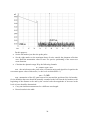
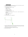
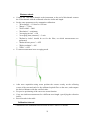
SVPRIBOR OPTICAL REFLECTOMETER (OTDR) SmartBOX User’s Guide TVER TABLE OF CONTENTS SAFETY CONSIDERATIONS ................................................................................... 3 GENERAL INFORMATION ...................................................................................... 3 PURPOSE ...................................................................................................................... 3 ENVIRONMENT ............................................................................................................. 3 SPECIFICATIONS ........................................................................................................... 3 DELIVERY SET ............................................................................................................. 5 INSTRUMENT DESIGN ................................................................................................... 6 POWER SUPPLY OF THE INSTRUMENT........................................................................... 7 GETTING STARTED AND SWITCHING ON THE INSTRUMENT................... 8 OTDR VIEW START ..................................................................................................... 8 TURNING ON OF THE DEVICE ........................................................................................ 8 OTDR CONNECTION TO AN OPERATING PLATFORM ..................................................... 9 CONNECTION OF OPTICAL FIBRE .................................................................... 11 WORK WITH THE DEVICE ................................................................................... 11 CONTROL OF NETWORK MANAGEMENT ...................................................... 12 CONTROL WEB INTERFACE ......................................................................................... 12 WI-FI SETTINGS ......................................................................................................... 13 ETHERNET SETTINGS ................................................................................................. 14 USB SETTINGS .......................................................................................................... 15 SERVICE ..................................................................................................................... 16 Password ............................................................................................ 16 Update ................................................................................................ 16 MAINTENANCE ........................................................................................................ 17 STORAGE RULES..................................................................................................... 17 TRANSPORT .............................................................................................................. 17 INSTRUMENT CALIBRATION .............................................................................. 18 VERIFICATION STAGES .............................................................................................. 18 CALIBRATION TOOLS ................................................................................................. 18 CALIBRATION ENVIRONMENT .................................................................................... 18 REALIZATION ............................................................................................................. 19 External examination and testing....................................................... 19 Dynamic range check ......................................................................... 19 Dead zone check ................................................................................. 21 Attenuation check ............................................................................... 22 Distance check .................................................................................... 23 CALIBRATION INTERVAL............................................................................................ 23 MANUFACTURER'S WARRANTY ....................................................................... 24 ACCEPTANCE CERTIFICATE .............................................................................. 24 2 SAFETY CONSIDERATIONS Concerning protection against electric shock the OTDR corresponds to GOST 12.2.091, equipment class III. In the field of laser safety the OTDR corresponds to GOST 12.1.040 and Class 1M of IEC 60825-1. OTDR can be handled by operator with qualifying group not lower than third, and knowing the technical operation of a fiber-optical measuring instruments. To avoid the contact of pulsed laser radiation with eyes do not connect and disconnect the optical fiber to the OTDR during measurements (when the laser is on). The laser safety label is applied on the OTDR panel. GENERAL INFORMATION Purpose Optical time domain reflectometer GAMMA-LITE (hereinafter "OTDR") is designed to measure the attenuation in optical fibers (OF) and their connections, OF length and distance to places of events in the optical cable and in OF in the fiber-optic transmission systems. The OTDR can be used in the manufacture of optical fibers and optical cables, as well as in the installation and operation of fiber-optic lines for control of cables and prediction of faults in them. OTDR can be operated in laboratory and field conditions. Environment Ambient air temperature from minus 10 to plus 50 С; Relative air humidity max. 90 % by 25 С; Atmospheric pressure from 70 to 106,7 kPa. Specifications Wavelength of optical radiation at the OTDR output: o 1,31 0,02 / 1,55 0,02 m. Ranges of measured distances for single-mode optical fiber: 0,2; 0,5; 1,2; 2,5; 5; 10; 25; 50; 100; 200 km. OTDR allows setting the values of the probe pulse width in the range of: 620 000 ns. Limits of acceptable absolute error of measuring distances make up: L = (dl + dL + L*n/n + 5*10-5*L), where o dl = 0,3 m; o dL - resolution (sampling interval of backscatter signal), defined by a prescribed range of the measured distance and the length of the measured span of OF m; dL 3 o o o o can take the values 0.2, 0.4, 0.8, 1.6, 3.1, 6.5 and 13,1 m and is set by the operator; L – OF length, m; n – OF refractive index; n – accuracy with which the refractive index is known for measured OF. The value of n can be set in the range from 1.00000 to 2.00000 with step 0.00001. Dynamic range = 33/31 dB (for a signal-to-noise ratio SNR = 1, measurement time 3 minute, pulse width = 20 000 ns and wavelength 1310/1550 nm). Note: The dynamic range may be decreased to 1.5 dB at maximum positive temperatures. Limits of permissible absolute error in measuring the attenuation is not more than ±(0,05 ), dB, where is the measured attenuation, dB. Minimum resolution in measuring the attenuation makes up 0,001 dB. The value of dead zone in measuring the attenuation is not more than 7 m with the probe pulse width of 6 ns and a reflectance of not more than minus 40 dB (in the switched-on "High Definition" mode). The value of dead zone for detecting events is not more than 3 m with the probe pulse width of 6 ns and a reflectance of not more than minus 40 dB (in the switchedon "High Definition" mode). OTDR provides two main measurement modes: with and without averaging the measurement results. In the averaging mode set the number of averages or measurement time. Single-mode fibers are connected to the OTDR through optical FC connector. Installation of optical connectors of other types is possible. Connection with IBM-compatible PC through USB connector. Management of the device from the remote computer according to the TCP/IP protocol is carried out via the Ethernet socket or on Wi-Fi. OTDR can be supplied from: o a built-in rechargeable battery; o an external power supply (1216) V o AC network with voltage (220 ± 22) V and frequency (50,0 ± 1) Hz via AC adapter with output voltage 15V, belongs to the delivery set. Battery charge time – 4 hours. OTDR dimensions 120х125х45 mm. OTDR weight 0,6 kg. 4 Delivery Set Designation Amount Instrument 1 AC adapter, output voltage 15V 1 From network 220 V USB interface cable 1 Connection with PC Ethernet interface cable (direct) 1 Connection with LAN Rechargeable battery 1 Inside of instrument Optical single-mode connection cable with FC connectors 1 CD with software 1 User’s Guide 1 5 Note Instrument Design SmartBOX is executed in the compact aluminum case without the screen. Carrying out measurements assumes use of additional devices on which OTDR View application launch is possible. Appearance of the front panel is shown on the following drawing: Hidden reset button Power ON/OFF button Front panel indicators: Power Power ON Indicator. Charge Charge of the battery Indicator Ready Индикатор готовности прибора. Ready of the SmartBOX Indicator Wi-Fi Wi-Fi Indicator 6 Connectors panel is shown on the following figure: USB port for data exchange with PC Ethernet connector for instrument control via TCP/IP External power supply connector Symbol «Caution! Laser radiation!» OTDR connector Power Supply of the Instrument The instrument is powered by a rechargeable LiIon battery. The battery compartment can be accessed from the side opposite to the connector panel. When the AC adapter is connected a fast battery charging takes place. Full-charge time does not exceed 4 hours. Charging process is indicated by a LED on the front panel of the instrument. The residual charge is monitored by program OTDR View. 7 GETTING STARTED AND SWITCHING ON THE INSTRUMENT The device has no own screen and is intended for collaboration with operating computer through the OTDR View program. The OTDR View program has options for work under the following operating systems: Windows, Linux, MacOS, Android. For communication with the device one of interfaces can be used: Wi-Fi, USB, Ethernet. OTDR Gamma Lite SmartBOX is ready to work right after Power On. The Wi-Fi is initially ON, IP-address by default 192.168.3.1. Connection on Ethernet is also possible, IP-address by default 192.168.1.1. After switching off of a wireless communication on page of settings (see «WLAN Settings») connection on USB will be available, IP-address by default 192.168.2.1. To change base settings it is possible via the web interface (see. «Control of network management»). OTDR View start The OTDR View program has options for work under various operating systems on different platforms. Appearance and management of the program depends on a platform. For a concrete operating system it is necessary to use the HELP. Start the otdrview.jar program from a delivery set. Connect your computer to the device Ethernet cable. Or Turn on your computer the Wi-Fi module. Turning on of the device Before you begin, make sure there are no mechanical damages to the instrument housing. If the instrument was stored or transported at temperatures below 0 C, it must be kept under normal conditions for 2 hours. To switch on the instrument press the Switching off is carried out by repeated pressing in long pressing of this button. key on the front panel 8 OTDR connection to an operating platform After turning on SmartBOX will be visible in the environment of Wi-Fi or Ethernet (after wait). Other Wi-Fi SmartBOX It is necessary to disconnect all other networks and to connect the SMARTBOX_OTDR network. In the OTDR View program choose "Device" and to "Connect". In drawing the OTDR View interface for Windows is shown. 9 Enter IP: In factory settings the following addresses are accepted: 192.168.1.1 for Ethernet 192.168.2.1 for USB 192.168.3.1 for Wi-Fi Press [OK] and the OTDR View program can operate the device. 10 CONNECTION OF OPTICAL FIBRE Connection OTDR to tested fiber is carried out via the FC type socket. ATTENTION! To avoid the contact of pulsed laser radiation with eyes do not connect and disconnect the optical fiber to the OTDR during measurements (when the laser is on). ATTENTION! Never connect the cables to the OTDR, if you are not sure of the purity of optical connectors. This can cause damage to the OTDR connector or lead to wrong results. WORK WITH THE DEVICE The OTDR View program has options for work under various operating systems on different platforms. Appearance and management of the program depends on a platform. For a concrete operating system it is necessary to use the HELP. 11 CONTROL OF NETWORK MANAGEMENT This section will help with the OTDR Gamma Lite SmartBOX control by means of the Web interface. Control web interface Open the Web browser and connect SmartBOX through Ethernet or Wi-Fi, The device IP address by default for Ethernet: 192.168.1.1., for Wi-Fi: 192.168.1.1. Enter the password. By default password: admin. If you changed settings and, let us assume, forgot the password, it is possible to come back to factory settings by pressed the hidden button The hidden button of reset in factory settings 12 Wi-Fi Settings Factory settings: IP address 192.168.3.1 Net mask 255.255.255.0 Press [Apply] for preservation of settings. The device will be reboot. 13 Ethernet Settings Factory settings: IP address 192.168.1.1 Net mask 255.255.255.0. Press [Apply] for preservation of settings. The device will be reboot. 14 USB Settings USB connection will be available if to switch off Wi-Fi (look “Wi-Fi Settings”) Factory settings: IP address 192.168.2.1 Net mask 255.255.255.0. 15 Service Factory settings: password – “admin”. Password Factory settings: password – “admin”. On page of authorization enter the new password. Press [Apply] for preservation of settings. The device will be reboot. For return to factory settings it is necessary to press and hold the reset button on the obverse panel of the device to a signal. The device will be reboot. Update Be convinced that the file with updating is on a hard disk. Click the [Browse…] button to choose the file. Then press to [Continue]. The device will be reboot. 16 MAINTENANCE Maintenance includes control inspection, during which are verified: completeness of the OTDR according to section "Delivery set"; absence of mechanical damage to the housing, front panel, connection elements. Identified defects must be eliminated. Optical connector of the OTDR should be regularly cleaned of contamination. To do this, make dense wick of cloth, intended for use with optical connectors, for example, Kimwipes, so that its thickness is slightly less than the inner diameter of the optical connector, moisten it with pure alcohol (isopropyl or ethyl alcohol) and carefully and gently wipe the connector inside the bush. After wiping let alcohol dry inside the connector bush, then you can measure. STORAGE RULES Until commissioning the OTDR should be stored in a warehouse under the following conditions: Ambient air temperature from 5 C to 40 С; Relative air humidity up to 80 % by 25 С. The repository should be free of dust, acid and alkali vapors and gases that cause corrosion. When the storage time exceeds one month the OTDR should be stored without the rechargeable battery. To remove the battery unscrew the two screws on the bottom side panel of the OTDR, take out the battery and set the covers in place. TRANSPORT Transportation of the OTDR must be carried out in closed vehicles of any kind (by rail, road and river (in holds) transport). During transportation by air the OTDR must be placed in a heated sealed compartment. The parameters of climatic impacts on the OTDR in packages during transportation should be the following: ambient air temperature from minus 20 to plus 50 C relative air humidity up to 98 % by 35 С; If the OTDR was transported at temperatures below 0 C, it must be kept under normal conditions for 2 hours. 17 INSTRUMENT CALIBRATION Verification Stages Test type Designation of operations Acceptance tests Periodic tests External examination and testing Yes Yes Dynamic range estimation Yes Yes Dead zones estimation Yes Yes Attenuation calibration Yes Yes Distance calibration Yes Yes Calibration Tools Name of test equipment Note Reference fiber 25 km Match throttle 1 km (2 pcs.) Use of other verification means is allowed that satisfy the requirements of this technique. Calibration Environment During verification the following conditions must be fulfilled: ambient air temperature (205) С; relative air humidity 3090 %; atmospheric pressure 84106 kPa; rechargeable battery completely charged. Measuring instruments must be prepared for work in accordance with maintenance documentation. Thoroughly clean the optical connectors before switching. 18 Realization External examination and testing During external examination the instrument compliance with the following requirements should be identified: completeness must meet the requirements of the log book; all the inscriptions on the instrument must be clear and distinct; the instrument shall not have mechanical damages on its housing and connecting terminals. Dynamic range check Connect the 25 km throttle to the instrument. Set the following parameters: o "Wavelength" = 1310 nm or 1550 nm o "Range" = 100 km o "Pulse width" = 20000 ns o "Resolution" = maximum o “Averaging in time” = ON o "Averaging time (minutes)" = 3 min. o "Refractive index" should be set for the fiber, on which measurements are performed. o "Reduced laser power" = OFF o "High resolution" = OFF o "Filter" = OFF or ON To start measurement in an averaging mode. After completion of trace acquisition carry out measurements. 19 For this purpose: Set the left marker just after the probe pulse. Set the right marker to the maximum burst of noise outside the phantom reflection area. Read the attenuation value D max. For precise positioning of the cursor use zoom function. Calculate the dynamic range D by the following formula: D D max D1 D2 D1 - the ratio between the peak value of Gaussian noise and signal level equal to the root-mean-square value of this noise (i.e. the level at which SNR = 1) D1 = 2,4 dB D2 –attenuation of the OF span between its start and the position of the left marker; for its definition the trace should be mentally extended to the left from the left marker to the beginning of the distance scale and by the vertical scale the magnitude of increase in the level of trace should be determined. Carry out similar measurements for a different wavelength. Record results in the table. 20 Dead zone check Connect the 1 km throttle to the instrument, to the end of this throttle connect one 1 km throttle more. Set the following parameters: o "Wavelength" = 1310 nm or 1550 nm o "Range" = 5 km o "Pulse width" = minimum o "Resolution" = minimum o “Averaging in time” = ON o "Averaging time (minutes)" = 3 min. o "Refractive index" should be set for the fiber, on which measurements are performed. o "Reduced laser power" = OFF o "High resolution" = ON o "Filter" = OFF To start measurement in an averaging mode. Measure the dead zone by the attenuation as the distance from the reflection start to the point at which the signal level of the photodetector does not differ by more than 0.5 dB from the level of backscattering. For precise positioning of the cursor use zoom function. Measure the event dead zone as the distance between the start of reflection and a point on the trailing edge of the reflection peak with level of 1.5 dB relative to the top. Carry out similar measurements for a different wavelength. Record results in the table. 21 Attenuation check Connect the 1 km throttle to the instrument, to the end of this throttle connect the 25 km throttle with the calibrated line attenuation. Set the following parameters: o "Wavelength" = 1310 nm or 1550 nm o "Range" = 75 km o "Pulse width" = 5000 o "Resolution" = minimum o “Averaging in time” = ON o "Averaging time (minutes)" = 3 min. o "Refractive index" should be set for the fiber, on which measurements are performed. o "Reduced laser power" = OFF o "High resolution" = ON o "Filter" = OFF To start measurement in an averaging mode. After trace acquisition enable the LSA line mode, position the cursors at the end and beginning of the linear span of the trace and compare the measured value of the slope in dB/km with certified value of the used 25 km coil. Carry out similar measurements for a different wavelength. Record results in the table. 22 Distance check Connect the 1 km match throttle to the instrument, to the end of this throttle connect the 25 km throttle with the calibrated refractive index and length. Set the same parameters as by attenuation calibration: o "Wavelength" = 1310 nm or 1550 nm o "Range" = 75 km o "Pulse width" = 5000 o "Resolution" = minimum o “Averaging in time” = ON o "Averaging time (minutes)" = 3 min. o "Refractive index" should be set for the fiber, on which measurements are performed. o "Reduced laser power" = OFF o "High resolution" = ON o "Filter" = OFF To start measurement in an averaging mode. After trace acquisition using zoom position the cursors exactly on the reflecting events of the start and end of a the calibrated optical fiber on the trace, and compare the derived distance with the certified value. For precise positioning of the cursor use zoom function. Carry out similar measurements for a different wavelength. (specifying the refraction index). Record results in the table Calibration Interval Calibration of the instrument must be made at least 1 time in 12 months. 23 MANUFACTURER'S WARRANTY Warranty period is 1 year from a purchase date. The warranty is not applied to the battery. All matters of warranty and post-warranty service of the instrument should be addressed to: 170030, TVER, Koroleva 9, SVYAZPRIBOR Phone/Fax +7 (4822) 42-54-91 www.svpribor.ru Technical support service: [email protected] When you send the instrument in for repair, please accompany it with the following information: Failure description Comments or suggestions to the work of the instrument Return address ACCEPTANCE CERTIFICATE Instrument serial number _________ Date _________ Signature _________ 24 CALIBRATION DATA Instrument No. _________________ Dynamic range 20 000 ns 1310 3 worst-case OFF ≥33 dB 20 000 ns 1550 3 worst-case OFF ≥31 dB Attenuation dead zone 6 ns 1310 3 best-case ON ≤7 m 6 ns 1550 3 best-case ON ≤7 m Reflection dead zone 6 ns 1310 3 best-case ON ≤3 m 6 ns 1550 3 best-case ON ≤3 m Distance 5 000 ns 1310 3 best-case ON 25,2524 ÷25,2590 km 5 000 ns 1550 3 best-case ON 25,2638 ÷25,2705 km Attenuation 5 000 ns 1310 3 worst-case ON 0,312 ÷ 0,344 dB/km 5 000 ns 1550 3 worst-case ON 0,182 ÷ 0,202 dB/km Calibrator Date 25 Actual value High resolution Norm Value Resolution Averaging time (min) Wavelength Pulse Conditions