1
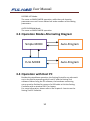
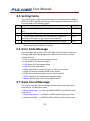
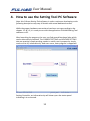
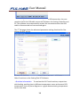
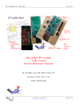
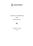
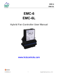
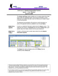
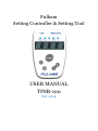
Fulham Setting Controller & Setting Tool USER MANUAL TPSB-100 Ver 1.0.4 User Manual Contents 1. Overview ............................................................................. 2 1.1 Supported Power Driver Products List............................ 2 1.2 Setting Controller Hardware Parts & Connections ......... 3 1.3 Host PC Hardware & Software Requirements ................ 5 2. Tool Software and Drivers Installation ................................ 6 2.1 Install the USB driver for the Setting Controller ............. 6 2.2 Install the Tool Software on a PC .................................... 7 3. How to use the Setting Controller ....................................... 8 3.1 SIMPLE MODE operation ‐ I/V setting ............................ 8 3.2 FULL MODE operation ‐ all features setting ................... 9 3.3 Operation Modes Alternating Diagram ........................ 10 3.4 Operation with Host PC ................................................ 10 3.5 Setting Items ................................................................ 11 3.6 Error Code Message ..................................................... 11 3.7 Beep Sound Message ................................................... 11 4. How to use the Setting Tool PC Software .......................... 12 5. Terminology ...................................................................... 14 6. Revision History ................................................................. 14 1 User Manual 1. Overview The Setting Controller & Setting Tool Software is designed for configuring the parameters of Fulham LED drivers. The tool set is an easy to use smart system that consists of a USB Programming Setting Controller, and the Fulham Setting Tool which is a Windows based PC software. It is designed for various field applications of lighting systems. With the configuration tool, lighting solutions manufacturers are allowed to batch set power parameters with factory settings in mass production under the high efficiency ‘Auto Program’ mode. Also end users can tune the parameters of FULHAM LED drivers for their dedicated applications with this powerful Setting Controller. 1.1 Supported Power Driver Products List √ T1M1UNV105P‐40E √ T1M1UNV105P‐40F √ T1M1UNV105P‐60E √ T1M1UNV105P‐60F √ T1A1UNV105P‐40E √ T1A1UNV105P‐60E Note: the list is continuously updated with new product types supported. 2 User Manual 1.2 Setting Controller Hardware Parts & Connections The setting controller: The entire setting system hardware consists of a setting controller and other accessories: √ FULHAM Setting Controller TPSB‐100 √ USB 2.0 Cable A‐type to Mini B type √ Programming Wire of 3.5mm head to 2‐Pin header with 3.5mm pitch √ Programming Wire of 3.5mm head to 2‐Pin header with 5.0mm pitch √ AC/DC power adapter 5v 1A for standalone operations. 3 User Manual The hardware configuration and connections: a. Plug the USB cable into the setting controller, then connect the cable to a host PC or power adapter for standalone mode operation. b. Connect the controller to the DUT (Device Under Test or the LED driver) by using the programming wire with the appropriate pitch. NOTE the POLARITY markings on the pin side of the programming wire correspond to the Polarity markings on the DUT. c. The controller will automatically power up and be ready for use. 4 User Manual 1.3 Host PC Hardware & Software Requirements The minimum computer hardware required to install and run Setting Tool Software: √ 1GHz CPU √ 512MB RAM √ USB Port 2.0/3.0 √ The Setting Tool Software supports the following Windows OS Family: Windows XP SP2 and above (32 & 64 bit) Windows Vista/Windows 7 (32 & 64 bit) Windows 8 (32 & 64 bit) The Setting Tool Software is a Windows PC application software from Fulham. This PC software can help our customers easily configure the LED drivers. This software can be downloaded from FULHAM website. 5 User Manual 2. Tool Software and Drivers Installation 2.1 Install the USB driver for the Setting Controller Before installing the USB driver and the Tool Software, it is strongly recommended for users to check whether the host PC already has the FTDI USB bridge driver installed. This procedure is suggested to avoid any unforeseen conflicts with the operating system of the PC. If the legacy version of the FTDI driver has been installed or any problems are encountered during the USB connection, the following FTDI Clean Utility can help users clean any previous driver installation safely. In most case Windows automatically locates and installs the driver for new found hardware. However, in case the OS does not automatically install, a manual installation of the USB driver is recommended using the following steps: Step1: Find the USB driver setup executable file, then run with administration privileges. For the FTDI FT230XS USB driver we recommend you to install with version 2.12.00 or higher. The latest FT230XS USB2COM bridge driver software can be downloaded from FTDI official website: http://www.ftdichip.com/FTDrivers.htm 6 User Manual Step2: Proceed with the installation instructions and the driver will automatically choose the right Windows OS version to finish the installation. Step3: After finishing the installation please confirm the driver information shown in the ‘Control Panel/Installation and Uninstallation’ section to confirm the successfully installation of USB driver. 2.2 Install the Tool Software on a PC The Setting Tool Software is an easy to install freeware with a very simple installation procedure. The setup file is in the installation package as following: By running the “setup.exe” file, the installation guide will automatically install the PC Setting Tool Software on your computer while the user only needs to choose the installation directory. After setting up and restarting the PC, the software is ready to run. The installation package can be downloaded from the official website of Fulham Inc. To prevent the possibility of encountering compatibility problems in the latest versions of Windows OS such as Windows7/8, it is preferred to start the program under compatible mode of Windows XP (Service Pack 2). 7 User Manual 3. How to use the Setting Controller 3.1 SIMPLE MODE operation ‐ I/V setting The Setting Controller enters SIMPLE MODE operation automatically after powering up with a short BEEP sound indicating its valid hardware self‐checks, and then the LED digits will display “SIMP”‐”ModE”. The user is able to use the normal Current or Voltage setting functions following the sequences below: ⊿ Press the “M” button to switch items between “Current(mA)” and “Voltage(V)” with “ISET”/”VSET” display indication. ⊿ Press the “+” or “‐” button to adjust the shown decimal value about to set. ⊿ Press the “Read” button to read out current/voltage value in the driver and display. When reading DUT failed, the screen digits would show “E‐02” or “E‐03” error code. After a successful reading the Controller would beep and show “R‐I”/”R‐V” and the read out value in alternative cycling. ⊿ Press the “Program” button to program current setting value into the DUT. After successful writing the Controller would beep then show “OK” and the setting current value in alternative cycling. If the process failed, it would show “E‐02” or “E‐03” error code. Note: Programming a 0 value current into the DUT makes its R‐SET function enabled. RECORD LIST Mode: In any status of the SIMPLE MODE, press the “M” button for over 2 seconds long to enter the RECORD LIST mode. The Setting Controller will show “SAVE” or “SAME” after entering this mode. ” SAME” means the current parameters have already been saved in the Record List before. It will then wait for the user to select whether to save or read the recorded setting parameters by pressing “+” or “‐” button to cycle items. The user can handle different record sets by selecting “OPEN”, ”DEL” and “BACK” options or recall one single current value/record set group(in Full Mode) to current memory, in the end by pressing the “M” button when the ” EXIT” shows to quit. AUTO PROGRAM Mode: 8 User Manual In order to program the same type DUT efficiently in a high volume batch operation flow, the user can start an AUTO PROGRAM Mode by pressing and holding the “Program” button after all the parameter values have been properly set in the Setting Controller. When the Controller shows “AUTO”, the user can press the “Program” button quickly 3 times to confirm entering the AUTO PROGRAM Mode or to cancel the operation. The controller will show “CHEK” and keep the dot of the last digit bright all the time to indicate a valid AUTO PROGRAM Mode. In this mode, the operator can put down the Setting Controller and keep plugging in and removing the DUT by using a dedicated pin‐head programming wire. In this batch operating mode, if a driver programming process fails the Controller will indicate an “E‐03” error and make a short beep sound. Otherwise it will show “OK” to indicate a successful programming process. Finally, the user can press and hold the “Program” button again until “MENU” is displayed, next quickly press the “Program” button 3 times to quit this AUTO PROGRAM Mode. 3.2 FULL MODE operation ‐ all features setting The Setting Controller will enter FULL MODE by pressing and holding both the “M” & “‐” buttons down until “FuLL”‐”ModE” is displayed while in the normal SIMPLE MODE operation. Next quickly press the “Program” button 3 times to make the Setting Controller enter the FULL MODE operation. After that, “READ” is shown to start getting full mode parameters value from the DUT or “CHEK” is shown if no DUT is connected. After entering this mode, pressing the “Read” button on the Setting Controller will allow you to read out all the parameters of the DUT. ⊿ Press the “M” button to cycle the display items of the parameters menu. ⊿ Press the “+” or “‐” button to adjust the shown value for the current item. ⊿ Press the “Read” button to read out parameters, just like in the SIMPLE MODE operation. ⊿ Press the “Program” button to program current set parameter values into the DUT while the Controller showing “REDY”. 9 User Manual RECORD LIST Mode: The same as SIMPLE MODE operation, while the cycle showing parameters are not Current Values but index numbers of the setting parameters. AUTO PROGRAM Mode: The same as SIMPLE MODE operation. 3.3 Operation Modes Alternating Diagram Simple MODE Auto‐Program FULL MODE Auto‐Program 3.4 Operation with Host PC Besides the standalone operation, the Setting Controller can also work out in the field by operating with a host PC and the Setting Tool software. Before using the PC software, the hardware connecting set‐up must be finished by means of a USB cable to link the Setting Controller with a windows OS PC or laptop. For more information, please refer to the chapter 4: how to use the Setting Tool PC Software. 10 User Manual 3.5 Setting Items No. The setting items in the Setting Controller are also divided into SIMPLE MODE and FULL MODE groups and all the implemented function items can be found in the following table: ITEMS MODE 1 √ Current: 0‐6000 (mA), 0 for R‐SET, actual range limited by SIMPLE DUT 2 √ Voltage: 0‐400 (v) SIMPLE FULL 3 √ CURV: DALI/LINE/LOG/CUST, to select the 3 different dimming curve types, or get custom curve from PC. 4 √ MinDim: Set a minimum dimming level of the output. FULL Note: the setting items may various to dedicated LED driver types which would have different functions. 3.6 Error Code Message The message code shown on the LED digits demonstrates some error message and other operating status information for users to make proper decision: →E‐01: Connection & communication failed →E‐02: Read DUT parameter failed →E‐03: Write DUT parameter failed →E‐04: Save Rec. data failed →CHEK: Check driver working status, or connection status →SAME: Parameter already saved in Rec. Mode →REDY: All setting parameters were finished and OK. →AUTO: Ready to go to automatic program mode →MANU: Ready to go to manual program mode 3.7 Beep Sound Message The sound message from the beeper demonstrates working mode switching or an operation result: →Mode Switching: on entering SIMPLE MODE, FULL MODE, short beep twice. →Operation Success: on PROG or READ success, beep one time. →Operation Failed: on PROG or READ failure, short beep 3 times. 11 User Manual 4. How to use the Setting Tool PC Software Note: this Fulham Setting Tool software is under continuous developing so the following description may vary in details with actual dedicated version. While the proper hardware connections have been set up according to the chapter 1.2 & 1.3, it is ready to run with the application FULHAM Setting Tool software on PC. After launching the program, the user can find several functional tabs which can be alternatively selected. The CURRENT SETTING and VOLTAGE SETTING tabs are practical simple working modes to satisfy user’s purpose by simply read or write V/I values directly. And even more, auto‐program is supported. If the communication has been successfully set up between the PC and the Setting Controller, an information tip will show up on the status panel indicating it is connected. 12 User Manual If this message doesn’t show after setting up the USB connection, the user needs to check the USB cable connection between the Setting Controller and PC. The software can automatically recover the connection when the USB cable is disconnected and reconnected again. The 3rd tab page shows the advanced parameter setting functions for fine tuning the DUT drivers. Other Functions on the Setting Tool PC Software: →Runtime Information: To read out the DUT total runtime, output time with loading, working time in different temperature zones and current PCB temperature, then to plot a diagram or a graph demonstrating temperature versus time data. 13 User Manual →Printing: Avery label printing for production line. →Custom Dimming Curve: The user can plot and generate a customized dimming curve for the DUT. →Log Files: Important data, time, operation mode and setting parameters information can be automatically saved in the local log file for data review and analysis later on. →Factory Settings: The SNID and other default data values can be scanned and preset into the DUT in mass production line under super user mode. →Thermal OTP: The OTP function is a reserved optional function for some driver types to fine tune the over temperature protection behaviors. This feature act as a output current fold‐back function when driver is running overheat. For more detailed information of PC software, please check the user manual PDF documentation in the Setting Tool software package or get the latest version online. 5. Terminology DUT. Device Under Test or the LED driver 6. Revision History Documentation revision history records: Last Modified Author First initiated TZ updated TZ updated TZ 14 Date 2015‐5‐25 2015‐6‐17 2015‐8‐12 Version 1.0.1 1.0.2 1.0.4