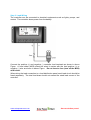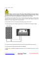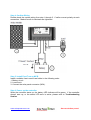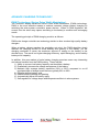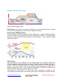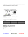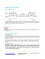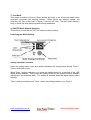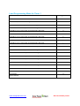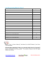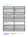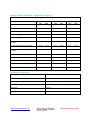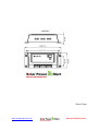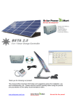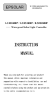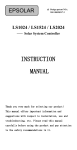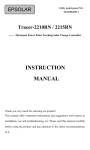
1
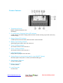
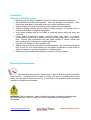
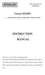
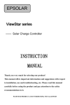
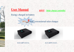
GAMMA 2.0 Thank you for choosing our product! This manual offers important information and suggestions about the installation, use and troubleshooting, etc. Please read this manual carefully before using the product and pay attention to the safety recommendations within. www.solarpower-mart.com Harvest the Sun power! USER MANUAL GAMMA 2.0 SOLAR CHARGE CONTROLLER RATINGS (Automatic 12V and 24V) NOTES: For use with solar panels and battery only TECHNICAL INFORMATION Auto 12 / 24 Volt DC Nominal System Voltage Maximum PV Input Voltage Nominal Charge / Discharge Current 12 / 24VDC 50V 3A, 5A or 10A The controller will recognize the system rated voltage when started up. If the battery voltage is lower than 18V, it will recognize the system as 12V. If the battery voltage is greater than 18V, it will recognize the system as 24V. www.solarpower-mart.com Harvest the Sun power! Notes, Cautions and Warnings This manual contains important safety, installation and operating instructions. The following symbols are used throughout this manual to indicate potentially dangerous conditions or mark important safety instructions, please take note of them. WARNING: Indicates a potentially dangerous condition. Use extreme caution when performing this task. CAUTION: Indicates a critical procedure for safe and proper operation of the controller. Note: Indicates a procedure or function that is important for the safe and proper operation of the controller. General Safety Guideline Read all of the instructions and cautionary symbols in the manual before beginning installation. There are no serviceable parts inside the controller. Do not disassemble or attempt to repair it. Install external fuses/Mini Circuit Breaker (MCB) as required. Disconnect the solar panel (module/PV) and fuse/MCB near the battery before installing or adjusting the controller. Do not allow water to enter the controller. Confirm that power connections are tightened to avoid excessive heating from a loose connection. www.solarpower-mart.com Harvest the Sun power! General Information Thank you for selecting GAMMA series solar controller that adopts the most advanced digital techniques and is fully automatic. The Pulse Width Modulation (PWM) battery charging can greatly increase the lifetime of the battery. It has various unique functions, such as: 12/24V automatic recognition. Highly efficient Series PWM charging increases the battery life and improves the solar PV system’ s performance. Uses MOSFET as electronic switch. Widely used, automatically recognize day/night technology. Digital LED display, only one key setting to program all functions. Intelligent timer function with 1-15 hours option. Unique dual timer function, enhance the flexibility of lighting system. Selectable Gel, Sealed and Flooded battery type options. Adopts temperature compensation, corrects the charging and discharging parameters automatically and improves battery life. Electronic protection from overheating, over charging, over discharging, overload, and short circuit. Reverse protection: any combination of solar module and battery. Support On Grid (grid-tie) solar panel (maximum PV voltage input 50V). Imbedded desulfator function from PWM technology. The controller is for multipurpose off-grid solar systems and enhances solar light system, protects the battery from being over charged by the solar module and over discharged by the loads. The charging process has been optimized for long battery life and improved system performance. The comprehensive self-diagnostics and electronic protection functions can prevent damage from installation mistakes or system faults.. Although the controller is easy to operate and use, please kindly study this user manual before you begin. This will help you make full use of the functions and you can improve your solar system. www.solarpower-mart.com Harvest the Sun power! Product Features 1. Temperature Sensor Measure ambient temperature and make temperature compensation for charging and discharging. 2. PV (solar panel) Charging Status LED indicator A LED indicator that shows charging status and also indicates warning signal when solar array connect wrongly. 3. Battery Status LED Indicator A LED indicator that shows battery status and other crucial information. 4. Battery Type Setting Indicator Select battery type indicator: SEL, GEL and Flood. 5. Timer 2 Setting Indicator The indicator will be on when set Timer 2. 6. Timer 1 Setting Indicator The indicator will be on when set Timer 1. 7. LED Digital Display Display the load program mode and status. 8. Setting Button (in manual mode used for load ON/OFF Switch) Set load program mode (Timer 1 & Timer 2) and select battery type. 9. Solar Module Terminals Connect solar modules. 10. Battery Terminals Connect batteries. 11. Load Terminals Connect loads. www.solarpower-mart.com Harvest the Sun power! Installation General Installation Notes: Read through the entire installation section first before beginning installation. Be careful when working with batteries. Wear eye protection if necessary. Have fresh water available to wash and clean any contact with battery acid. Uses insulated tools and avoid placing metal objects near the batteries. Explosive battery gasses may be present during charging. Be certain there is sufficient ventilation to disperse the gasses. Avoid direct sunlight and do not install in locations where water can enter the controller. Loose power connections and/or corroded wires may result in resistive connections that melt wire insulation, burn surrounding materials, or even cause fires. Ensure tight connections and use cable clamps to secure cables and prevent them from swaying from mobile applications. Use with Gel, Sealed or Flood batteries only. Battery may be wired to one battery or more batteries. The following instructions refer to the use of a single battery, but the battery connection can be made to either one battery or a group of batteries in a battery bank. Select the system cables accordingly or consult us for more details. Mounting Requirements NOTE: When mounting the controller, ensure there is free air flow through the controller heat sink fins. There should be at least 6 inches (150 mm) of clearance above and below the controller to allow for cooling. If mounted in an enclosed space, providing ventilation is highly recommended. WARNING: Risk of explosion! Never install the controller in a sealed enclosed area with flood batteries! Do not install in a confined area where battery gass can accumulate. www.solarpower-mart.com Harvest the Sun power! Step 1: Choose Mounting Location Place the controller on a vertical surface protected from direct sunlight, high temperature, and moisture. Provide good ventilation. Step 2: Check for clearance Place the controller at the location where it will be mounted. Verify that there is sufficient room to run the wires and that there is sufficient room above and below the controller for air flow. Step 3: Mark Holes Use a pencil or pen to mark the four (4) mount points on the surface. Step 4: Drill Holes Remove the controller and drill 4.5mm holes in the marked locations. Step 5: Secure Controller Place the controller on the surface and align the mounting holes with the drilled holes in step 4. Secure the controller in place using the mounting screws. www.solarpower-mart.com Harvest the Sun power! Wiring NOTE: A recommended connection order (step by step) has been created to provide maximum safety during installation. NOTE: The controller is a common positive ground controller. CAUTION: Do not connect the loads with surge power exceeding the rating of the controller. CAUTION: For mobile applications, be sure to secure all wiring. Use cable clamps to prevent cables from swaying when the vehicle/object is in motion. Unsecured cables create loose and resistive connections which may lead to excessive heating and/or fire. www.solarpower-mart.com Harvest the Sun power! Step1: Battery Wiring WARNING: Risk of explosion or fire! Never connect the positive (+) and negative (-) battery cables. Before battery is connected, make sure that the battery voltage is greater than 6V to start up the controller. If the system is 24V, make sure battery voltage is not less than 18V. During the first start up, the controller will automatically recognize the system voltage. When installing a fuse or Mini Circuit Breaker (MCB), make sure that the distance between the fuse holder and the positive terminal of battery does not exceed 150mm. Do not insert a fuse (MCB) at this time. Make sure the battery cable is less than 0.5 meter long to prevent power loss. Always keeps the controller as close as possible so that it can sense the battery temperature for effective charging (temperature compensation). www.solarpower-mart.com Harvest the Sun power! Step 2: Load Wiring The controller can be connected to electrical equipments such as lights, pumps, and motors. The controller draws power from the battery. Connect the positive (+) and negative (-) controller load terminals as shown in above Figure. A fuse holder (MCB) should be wired in series with the load positive (+) or negative (-) wire as shown in above Figure. Do not insert a fuse (turn off the MCB) at this time. When wiring the load connection to a load distribution panel, each load circuit should be fused separately. The total load draw should not exceed the rated load current of the controller. www.solarpower-mart.com Harvest the Sun power! Step 3: Solar wiring WARNING: Risk of electric shock! Be caution when handling solar panel wiring. The high voltage from solar panel’s can induce electric shock and injury. Keep the solar panel away from sunlight before installing the solar wiring. The controller cans accept 12V or 24V nominal off-grid solar panel(s). Grid-tie solar panel(s) may be used if the open circuit voltage of solar panel doesn’ t exceed the Maximum PV input voltage (50V) of the controller. If using Grid-tie (On-Grid) solar panel, the battery system must be 24V. The solar panel(s) work voltage must be equal to or greater than the system voltage. For a good set up, please kindly use solar connector like the MC4 solar connector. Do not connect the solar connector (MC4) immediately. A MCB can be installed in between solar panel and the controller as a fuse or circuit breaker. www.solarpower-mart.com Harvest the Sun power! Step 4: Confirm Wiring Double-check the system wiring from step 1 through 3. Confirm correct polarity at each connection. Make sure all six terminals are tightened. Step 5: Install Fuse/Turn on MCB Install a suitable fuse in each fuse holder in the following order: 1. Battery circuit 2. Load circuit 3. Connect the solar panel connector (MC4). Step 6: Power up the controller When the controller starts up, the battery LED indicator will be green. If the controller doesn't start up, or the status LED error is active, please refer to Troubleshooting Section. www.solarpower-mart.com Harvest the Sun power! ADVANCE CHARGING TECHNOLOGY PWM Technology (Series Pulse Width Modulation) The controller adopts Advanced Series Pulse Width Modulation (PWM) technology. PWM is the most effective means to achieve constant voltage battery charging by switching the solar system controller’ s power devices. When in PWM regulation, the current from the solar array tapers according to the battery’ s condition and recharging needs. The operating principle of PWM charging mode is as follows: PWM solar charge controller use technology similar to other modern high quality battery chargers. When a battery voltage reaches the regulation set point, the PWM algorithm slowly reduces the charging current to avoid heating and gassing of the battery, yet the charging continues to return the maximum amount of energy to the battery in the shortest time. The result is a higher charging efficiency, rapid recharging, and a healthy battery at full capacity. In addition, this new method of solar battery charging promises some very interesting and unique benefits from the PWM pulsing. These include: 1) Ability to recover lost battery capacity and desulfate a battery. 2) Dramatically increase the charge acceptance of the battery. 3) Maintain high average battery capacities (90% to 95%) compared to on-off regulated state of charge levels that are typically 55% to 60%. 4) Equalize drifting battery cells. 5) Reduce battery heating and gassing. 6) Automatically adjust for battery aging. 7) Self-regulate for voltage drops and temperature effects in solar systems. www.solarpower-mart.com Harvest the Sun power! Battery Charge Information Figure: PWM charging mode Bulk Charge In this stage, the battery voltage has not yet reached the boost voltage and 100% of available solar power is used to charge the battery. Boost Charge/ PWM Regulation When the battery has been charged to boost voltage point, constant-voltage regulation is used to prevent over-heating and excessive battery gas releases. The boost stage remains for 120 minutes and then reduces into a float charge. This is where the PWM technology applies. Float Charge After the battery is fully charged in boost voltage stage, the controller reduces the battery voltage to float voltage set point. When the battery is fully charged, there will be no more chemical reactions and all the charge current transmits into heat and gas at this time. Then the controller reduces the voltage to the floating stage, charging with a smaller voltage and current. It will reduce the temperature of battery and prevent gas release, and also charges the battery with a low current. The purpose of float stage is to offset the power consumption caused by self consumption and small loads in the whole system, while maintaining full battery storage www.solarpower-mart.com Harvest the Sun power! capacity. In float stage, loads can continue to draw power from the battery. In the event that the system load(s) exceed the solar charge current, the controller will no longer be able to maintain the battery at the float set point. Should the battery voltage remains below the boost set point, the controller will exit float stage and return to bulk charge. Equalize Charge WARNING: Risk of explosion! Equalizing flood batteries can produce explosive gases, so well ventilated battery boxes are necessary. NOTE: Equipment damage! Equalization may increase battery voltage and can cause damaged to sensitive DC loads. Ensure that all loads allow input voltages that are greater than the equalizing charging set point voltage. NOTE: Equipment damage! Over-charging and excessive gas precipitation may damaged the battery plates and activate material shedding on them. Too high or too long an equalizing charge may cause damage. Please carefully review the specific requirements of the battery used in the system. Certain types of batteries benefit from periodic equalizing charges, which can stir up the electrolyte, balance the battery voltage and complete certain chemical reactions. Equalizing charges increase battery voltage; higher than the standard complement voltage, which gasifies the battery’ s electrolyte. If the battery is over discharged, the solar controller will automatically switch into the equalizing charge stage, and it remains as such for 120mins. The Equalizing charge www.solarpower-mart.com Harvest the Sun power! and boost charge are not carried out constantly in a full charge process so as to avoid too much gas precipitation or heat generation in the battery. LED INDICATION Charging Status indicator GREEN ON whenever sunlight is available for battery charging, GREEN FAST FLASHING when system is over voltage. Please refer to Troubleshooting Section for more detail. Charging Status LED Indicator Color Indicator Charging Status Green On Solid Charging Green Fast Flashing Overvoltage Battery Status indicator GREEN ON when battery voltage in normal range GREEN SLOWLY FLASHING when battery full ORANGE ON when battery under voltage RED ON when battery is over discharged. Please refer to Troubleshooting Section for more details. www.solarpower-mart.com Harvest the Sun power! Battery Status LED Indicator Color Indicator Battery Status Green On Solid Normal Green Slowly Flashing Full Orange On Sold Under voltage Red On Sold Over discharged Load Status Indicator: When the load current is 1.25 times of rated current for 60 seconds, or the load current is 1.5 times of rated current for 5 seconds (overload); or load current is more than 3.5 times of rated current (Short Circuit) ,the LED digital display will show “L”and flash slowly. Please refer to Troubleshooting Section for more details. Load Status LED Indicator Color LED Digital Display Load Status Red Overload or short circuit “L”with slowly flashing Overheating Protection Indicator: When heat sink of the controller exceeds 85°C, the controller will automatically cut the input and output circuit, with LED digital display showing “H”with flash slowly. Please refer Troubleshooting Section for more details. Overheating Protection Indicator Color LED Digital Display Load Status Red Controller overheating www.solarpower-mart.com “H”with slowly flashing Harvest the Sun power! TIMER SETTING FUNCTION Dual Timer Function The default night length setting is 10 hours. The controller can learn the night period by referring the night before. It also can adapt to the different seasons (day light saving). However, it may require time to adjust and learn. Notes: When Timer 2 is disabling, the controller will turn off the load output at the sunrise time. Load Controller Settings 1. Dusk to Dawn When solar module voltage goes below the point of Night Time Threshold Voltage (NTTV) at dusk/sunset, the controller will recognize the starting voltage and turn on the load after 10 minutes. When solar module voltage goes above point of Day Time Threshold Voltage (DTTV), the solar controller will recognize the starting voltage and turn off the load after 10 minutes. 2. Light ON + Timer When solar module voltage goes below the point of NTTV (Night Time Threshold Voltage) at sunset; the solar controller will recognize the starting voltage and turn on the load after 10 minutes delay. The load will be on for several hours which users set through LED digital display. The controller has dual timer function. Please refer to table “Load Programming Mode Settings”. www.solarpower-mart.com Harvest the Sun power! 3. Test Mode This mode is similar to Dusk to Dawn setting, but there is no 10 minutes delay when controller recognizes the starting voltage. When below the starting voltage, the controller will turn on the load, if higher, it will turn off load. The test mode makes it easy to check the solar lighting system during installation. 4. ON/OFF Mode (Manual Switcher) This mode is to turn ON and OFF the load by manual setting. Load Program Mode Setting Setting Operation Indicator Press the setting button once and setting indicators will change once among Timer 1, Timer 2 and battery type. When Timer 1 setting indicator is on, press the setting button for 5 seconds till the LED digital display flashes. Then press the setting button till the desired number appears according to the following table. The setting is finished when the digital display stops flashing. Timer 2 setting is the same as Timer 1 when the setting indicator is on Timer 2. www.solarpower-mart.com Harvest the Sun power! Load Programming Mode for Timer 1 Timer 1 LED Digital No. Disable n Dusk to Dawn, load will be on all night 0 Load will be on for 1 hour (with 10 minutes delay) after dusk. 1 Load will be on for 2 hours (with 10 minutes delay) after dusk. 2 Load will be on for 3 hours (with 10 minutes delay) after dusk. 3 Load will be on for 4 hours (with 10 minutes delay) after dusk. 4 Load will be on for 5 hours (with 10 minutes delay) after dusk. 5 Load will be on for 6 hours (with 10 minutes delay) after dusk. 6 Load will be on for 7 hours (with 10 minutes delay) after dusk. 7 Load will be on for 8 hours (with 10 minutes delay) after dusk. 8 Load will be on for 9 hours (with 10 minutes delay) after dusk. 9 Load will be on for 10 hours (with 10 minutes delay) after dusk. 10 Load will be on for 11 hours (with 10 minutes delay) after dusk. 11 Load will be on for 12 hours (with 10 minutes delay) after dusk. 12 Load will be on for 13 hours (with 10 minutes delay) after dusk. 13 Load will be on for 14 hours (with 10 minutes delay) after dusk. 14 Load will be on for 15 hours (with 10 minutes delay) after dusk. 15 Test Mode 16 On/Off Mode Manual Switcher 17 www.solarpower-mart.com Harvest the Sun power! Load Programming Mode for Timer 2 Timer 2 LED Digital No. Disable n Load will be on for 1 hour before dawn. 1 Load will be on for 2 hours before dawn. 2 Load will be on for 3 hours before dawn. 3 Load will be on for 4 hours before dawn. 4 Load will be on for 5 hours before dawn. 5 Load will be on for 6 hours before dawn. 6 Load will be on for 7 hours before dawn. 7 Load will be on for 8 hours before dawn. 8 Load will be on for 9 hours before dawn 9 Load will be on for 10 hours before dawn. 10 Load will be on for 11 hours before dawn. 11 Load will be on for 12 hours before dawn. 12 Load will be on for 13 hours before dawn. 13 Load will be on for 14 hours before dawn. 14 Load will be on for 15 hours before dawn. 15 Notes: If Timer 1 is Dusk to Dawn (0), Test Mode (16) or ON/OFF Mode (17), the Timer 2 will be disabled. When the battery typesetting indicator is on, press the setting button for 5 seconds till the LED digital display flashes. Then press the setting button till the desired number appears according to the following table. The setting is finished till the LED digital display stops flashing. www.solarpower-mart.com Harvest the Sun power! Battery Type Setting Battery Type Digital LED Display Sealed Lead Acid Battery/AGM 1 Gel Battery 2 Flooded Battery 3 www.solarpower-mart.com Harvest the Sun power! TROUBLESHOOTING Protection PV Array Short Circuit If PV array short circuit occurs, clear it to resume normal operation. Load Overload If the load current exceeds the maximum load current rating, the controller will disconnect the load. The greater the overload, the faster the load will be disconnected. A small overload could take a few minutes to disconnect. Overloading must be cleared up through reapply power or pressing the setting button. Load Short Circuit Fully protected against load wiring short-circuit. After one automatic load reconnect attempt, the faulty error must be cleared by reapply power or pressing the setting button. PV Reverse Polarity The controller fully protects against PV reverse polarity, therefore no damage to the controller. Please check and re-correct the wire to resume operation. Battery Reverse Polarity The controller fully protects against battery reverse polarity, therefore no damage to the controller. Please check and re-correct the wire to resume operation. Damaged Local Temperature Sensor If the temperature sensor short-circuited or damaged, the controller will be charging or discharging at the default temperature of 25°C to prevent the battery damaged from overcharging or over discharged. Overheating Protection If the controller’ s internal temperature exceeds 85°C, the controller will automatically start the overheating protection. High Voltage Transients Battery is protected against high voltage transients. In lightning prone areas, a lighting arrestor is highly recommended. www.solarpower-mart.com Harvest the Sun power! Problem Possible Causes Possible Solutions PV Charging Status LED indicator light off during daytime (when sunlight presence). PV array may be disconnected Check PV and battery wire connections. PV Charging Status LED indicator turned green with fast flashing Battery voltage higher than Over Voltage Disconnect voltage(OVD) Check if battery voltage. Disconnect the solar module Battery Status LED Indicator turned orange Battery under voltage Load output is normal, charging LED indicator will return to green when battery fully charged by PV. Battery Status LED Indicator turned red and loads turned off. Battery over discharged The controller cut off the load output to prevent over discharge, LED indicator will return to green when battery fully charged. LED Digital Displays shown “L”with red slowly flashing Overload or short circuit occurred Overload: Please reduce the load and press the setting button once, the controller will resume to normal operation after 3s; Short circuit: when the first short-circuit occurs, the controller will automatically resume to normal operation after 10s; When a second short-circuit occurs, press the button, the controller will resume to normal operation after 3s. LED Digital Displays shown “H”with red slowly flashing Controller temperature is too high. When heat sink of the controller exceeds 85℃ , the controller will cut off power input and output. When the temperature below 75℃ , the controller will resume to normal operation. Notes: No Battery Status LED Indicator - Please measure battery voltage with a multimeter. The minimum requirement is 6V to start up the controller. Notes: No PV Charging Status LED indicator (when sunlight presence) - Please measure the solar panel input voltage and the input voltage must higher than the battery voltage (12V or 24V). www.solarpower-mart.com Harvest the Sun power! MAINTENANCE The following inspections and maintenance tasks are recommended at least twice per year for best controller performance. Notes: Danger of electrocution! Make sure that all power source of controller is cut off when operate above processes, and then make inspection or other operations! Check the controller is securely mounted in a clean and dry environment. Check the air flow and ventilation around the controller is not blocked. Clear dirt or fragments on the heat sink. Check all wires to make sure insulation is not damaged for serious solarization, frictional wear, dryness, insects or rats etc. Maintain or replace the wires if necessary. Tighten all the terminals. Inspect for loose, broken, or burnt wire connections. Check and confirm that LED digital display is consistent with setting requirement. Pay attention to any error indication and take necessary action. Confirm all system components are ground connected tightly and correctly. Confirm all the terminals have no corrosion, insulation damaged, high temperature or burnt/discolored sign, tighten terminal screws to the suggested torque. Inspect for dirt, insects and corrosion, and clear up such obstructions. Check and confirm lightning arrester is in good condition. Replace a new one in time to avoid damaging of the controller and other equipments. www.solarpower-mart.com Harvest the Sun power! LIMITED PRODUCT WARRANTY SC Origin (M) Sdn Bhd (SCO) warrant to the original purchaser that the GAMMA charge controller is free from manufacturer defects in material, assembly, and workmanship under normal use for a period of ONE (1) year from the date of original purchase subject to the terms and conditions of this Limited Product Warranty (“Limited Warranty”). By using GAMMA charge controller, you as the original purchaser are asked to carefully read and agree to the following terms and conditions of this Limited Warranty before you use the product. Your use of this product constitutes agreement with all provisions of this warranty. Purchasing this controller from a third party vendor negates all warranties (expressed or implied) in this warranty. If any defects due to manufacturing should arise during the first year of purchase and all terms and conditions of the Limited Warranty have been met, SCO will at its option, either repair or replace the product to the original purchaser without charge. If the product cannot be repaired within a reasonable time or a reasonable price, SCO may elect to refund the purchase price instead. No warranty work will be provided without the purchaser’ s receipt or other proof of the date of original purchase acceptable to SCO. This shall be SC Origin (M) Sdn Bhd maximum and total liability. This warranty does not apply under the following conditions: 1. Damage by accident, negligence, abuse or improper use. 2. PV or load current exceeding the ratings of product. 3. Unauthorized product modification or attempted repair. 4. Damaged occurring during shipment. 5. Damage results from acts of nature disaster such as lightning, floods, fire, wind, etc. 6. Irreclaimable mechanical damage. 7. Damages exceeding the total cost of the controller. 8. The finish on any portion of the controller (i.e. surface scratches, weathering, corrosion, as this is considered normal wear and tear.) 9. Transit damage, initial installation costs, removal costs, or reinstallation costs. 10. Improper maintenance, installation and/or operation of the controller in other than a normal operating condition or in such a way as to otherwise fail to comply with the instructions or manuals thereof or otherwise constitute misuse. SCO do not incur liability for any of the following in any event: Personal injury; Direct, indirect, special, incidental, multiple or consequential damages. www.solarpower-mart.com Harvest the Sun power! Claim procedure: Before requesting warranty service, check the User Manual to be certain that there is a problem with the controller. Return the defective product to SCO with shipping charges prepaid if problem cannot be solved. Provide proof of date and place of purchase. To obtain rapid service under this warranty, the returned products must include the model, serial number and detailed reason for the failure, the module type and size, type of batteries and system loads. This information is critical to a rapid disposition of your warranty claim. THE LIMITED WARRANTY IS THE ONLY WARRANTY OF SC ORIGIN (M) SDN BHD. THERE ARE NO OTHER WARRANTIES, EXPRESSED OR IMPLIED, EXCEPT AS PROVIDED BY LAW, INCLUDING THE IMPLIED WARRANTY OF QUALITY, MERCHANTABILITY OR FITNESS FOR A PARTICULAR PURPOSE AND SUCH IMPLIED WARRANTIES, IF ANY, ARE LIMITED IN DURATION TO THE TERM OF THE LIMITED WARRANTY. www.solarpower-mart.com Harvest the Sun power! TECHNICAL SPECIFICATION Electrical Parameter Description Parameter Nominal System Voltage 12 / 24VDC Auto work Battery Voltage Range 6-36V Rated Battery Current GAMMA-3A GAMMA-5A GAMMA-10A Charge Circuit Voltage Drop ≤0.26V Discharge Circuit Voltage Drop ≤0.15V Self-consumption ≤6mA Threshold Voltage Parameter Description 3A 5A 10A Parameter NTTV (Night Time Threshold Voltage) 5V for 12V system; 10V for 24V system DTTV (Day Time Threshold Voltage) 6V for 12V system; 12V for 24V system Temperature Compensation Coefficient Description Temperature Compensation Coefficient(TEMPCO)* Parameter -30mV/℃ /12V(25 ref) Compensation of equalize, boost, float and boost reconnect voltage Environmental Parameter Description Parameter Working temperature -35°C to +55°C Storage temperature -35°C to +80°C Humidity 10%-90% NC Enclosure IP30 www.solarpower-mart.com Harvest the Sun power! Battery Voltage Parameter (Temperature at 25°C) Charging Parameter Battery Charging Setting Over Voltage Disconnect Voltage 12V 16V Gel 24V 32V Sealed 12V 24V 16V 32V Flooded 12V 24V 16V 32V Charging Limit Voltage 15.5V 31V 15.5V 31V 15.5V 31V Equalize Charging Voltage N/A 14.6V 29.2V 14.8V 29.6V Boost Charging Voltage 14.2V 28.4V 14.4V 28.8V 14.6V 29.2V Float Charging Voltage 13.8V 27.6V 13.8V 27.6V 13.8V 27.6V Boost Reconnect Charging Voltage 13.2V 26.4V 13.2V 26.4V 13.2V 26.4V Low Voltage Reconnect Voltage 12.6V 25.2V 12.6V 25.2V 12.6V 25.2V Under voltage warning reconnect voltage 12.2V 24.4V 12.2V 24.4V 12.2V 24.4V Under Voltage Warning Voltage 12V 24V 12V 24V 12V 24V Low Voltage Disconnect Voltage 11.1V 22.2V 11.1V 22.2V 11.1V 22.2V Discharging Limit Voltage 10.8V 21.6V 10.8V 21.6V 10.8V 21.6V Equalize Duration Boost Duration Mechanical Parameter Description 2 hours 2 hours 2 hours 2 hours 2 hours Parameter Overall dimension 140(5.51) x 65(2.56) x 34(1.34) mm/inches Mounting dimension 130(5.12) x 45(1.77) mm/inches Mounting hole size Φ4.5 Terminal 6mm2 Net weight 0.15kg www.solarpower-mart.com Harvest the Sun power! End of Page www.solarpower-mart.com Harvest the Sun power!