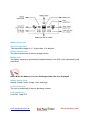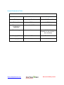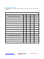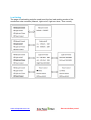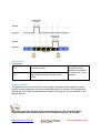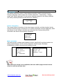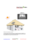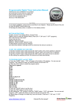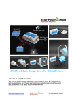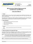
1
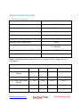
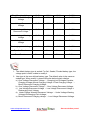
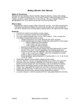
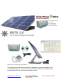
Sealed Acid Battery Gel Battery Flooded Battery Lithium Battery Customize Battery Thank you for choosing our product! This manual offers important information and suggestions about the installation, use and troubleshooting, etc. Please read this manual carefully before using the product and pay attention to the safety recommendations within. www.solarpower-mart.com Harvest the Sun power! USER MANUAL BETA 2.0 15A - 20A 5 IN 1 SOLAR CHARGE CONTROLLER RATINGS (Automatic 12V and 24V) NOTES: For use with solar panels and battery only TECHNICAL INFORMATION Auto 12 / 24 Volt DC Nominal System Voltage Maximum PV Input Voltage Nominal Charge / Discharge Current 12 / 24VDC 50V 15A and 20A The controller will recognize the system rated voltage when started up. If the battery voltage is lower than 18V, it will recognize the system as 12V. If the battery voltage is greater than 18V, it will recognize the system as 24V. www.solarpower-mart.com Harvest the Sun power! Notes, Cautions and Warnings This manual contains important safety, installation and operating instructions. The following symbols are used throughout this manual to indicate potentially dangerous conditions or mark important safety instructions, please take note of them. WARNING: Indicates a potentially dangerous condition. Use extreme caution when performing this task. CAUTION: Indicates a critical procedure for safe and proper operation of the controller. Note: Indicates a procedure or function that is important for the safe and proper operation of the controller. General Safety Guideline Read all of the instructions and cautionary symbols in the manual before beginning installation. There are no serviceable parts inside the controller. Do not disassemble or attempt to repair it. Install external fuses/Mini Circuit Breaker (MCB) as required. Disconnect the solar panel (module/PV) and fuse/MCB near the battery before installing or adjusting the controller. Do not allow water to enter the controller. Confirm that power connections are tightened to avoid excessive heating from a loose connection. www.solarpower-mart.com Harvest the Sun power! General Information Thank you for selecting BETA 2.0 series solar controller that adopts the most advanced digital techniques programming and is fully automatic. The Pulse Width Modulation (PWM) battery charging can greatly increase the lifetime of the battery. It has various unique functions, such as: 12/24V automatic recognition. Highly efficient Series PWM charging increases the battery life and improves the solar PV system’ s performance. Uses MOSFET as electronic switch. Widely used, automatically recognize day/night technology. New SOC method of calculating accurately displays the available battery capacity. With functions of current power calculation and real-time energy statistics recording, it is convenient for users to view charging and discharging energy of each day, month, year and total value. Use of standard Modbus communication protocol for RS-485 bus connections, making communication distance much longer and communication protocol compatibility much better. Intelligent timer function with 1-15 hours option (Program with Remote Meter). Unique dual timer function, enhance the flexibility of lighting system (Program with Remote Meter). Programmable Lithium, Gel, Sealed, Flooded, Customize battery type options. Adopts temperature compensation, corrects the charging and discharging parameters automatically and improves battery life. Electronic protection from overheating, over charging, over discharging, overload, and short circuit. Reverse protection: any combination of solar module and battery. Support On Grid (grid-tie) solar panel (maximum PV voltage input 50V). Imbedded desulfator function from PWM technology. The controller is for multipurpose off-grid solar systems and enhances off grid solar system, protects the battery from being over charged by the solar module and over discharged by the loads. The charging process has been optimized for long battery life and improved system performance. The comprehensive self-diagnostics and electronic protection functions can prevent damage from installation mistakes or system faults. Although the controller is easy to operate and use, please kindly study this user manual before you begin. This will help you make full use of the functions and you can improve your solar system. www.solarpower-mart.com Harvest the Sun power! Product Features 2 5 3 4 6 7 8 9 1 1. Temperature Sensor Measure ambient temperature and make temperature compensation for charging and discharging. 2. PV (solar panel) Charging Status LED indicator A LED indicator that shows charging status and also indicates warning signal when solar array connect wrongly. 3. Battery Status LED Indicator A LED indicator that shows battery status and other crucial information. 4. Load On & Off Switch Manually turn on or turn off the DC load. 5. DC Load LED Indicator Display the load status. 6. Solar Module Terminals Connect solar modules. www.solarpower-mart.com Harvest the Sun power! 7. Battery Terminals Connect batteries. 8. Load Terminals Connect loads. 9. PC Network Connection or Data Logger Connection Connect to PC or Remote Meter for programming. www.solarpower-mart.com Harvest the Sun power! Installation General Installation Notes: Read through the entire installation section first before beginning installation. Be careful when working with batteries. Wear eye protection if necessary. Have fresh water available to wash and clean any contact with battery acid. Uses insulated tools and avoid placing metal objects near the batteries. Explosive battery gasses may be present during charging. Be certain there is sufficient ventilation to disperse the gasses. Avoid direct sunlight and do not install in locations where water can enter the controller. Loose power connections and/or corroded wires may result in resistive connections that melt wire insulation, burn surrounding materials, or even cause fires. Ensure tight connections and use cable clamps to secure cables and prevent them from swaying from mobile applications. Use with Lithium, Gel, Sealed or Flood batteries only. Battery may be wired to one battery or more batteries. The following instructions refer to the use of a single battery, but the battery connection can be made to either one battery or a group of batteries in a battery bank. Select the system cables accordingly or consult us for more details. Mounting Requirements NOTE: When mounting the controller, ensure there is free air flow through the controller heat sink fins. There should be at least 6 inches (150 mm) of clearance above and below the controller to allow for cooling. If mounted in an enclosed space, providing ventilation is highly recommended. WARNING: Risk of explosion! Never install the controller in a sealed enclosed area with flood batteries! Do not install in a confined area where battery gases can accumulate. www.solarpower-mart.com Harvest the Sun power! Step 1: Choose Mounting Location Place the controller on a vertical surface protected from direct sunlight, high temperature, and moisture. Provide good ventilation. Step 2: Check for clearance Place the controller at the location where it will be mounted. Verify that there is sufficient room to run the wires and that there is sufficient room above and below the controller for air flow. Step 3: Mark Holes Use a pencil or pen to mark the four (4) mount points on the surface. Step 4: Drill Holes Remove the controller and drill 4.5mm holes in the marked locations. Step 5: Secure Controller Place the controller on the surface and align the mounting holes with the drilled holes in step 4. Secure the controller in place using the mounting screws. www.solarpower-mart.com Harvest the Sun power! Wiring NOTE: A recommended connection order (step by step) has been created to provide maximum safety during installation. NOTE: The controller is a common positive ground controller. CAUTION: Do not connect the loads with surge power exceeding the rating of the controller. CAUTION: For mobile applications, be sure to secure all wiring. Use cable clamps to prevent cables from swaying when the vehicle/object is in motion. Unsecured cables create loose and resistive connections which may lead to excessive heating and/or fire. www.solarpower-mart.com Harvest the Sun power! Step1: Battery Wiring WARNING: Risk of explosion or fire! Never connect the positive (+) and negative (-) battery cables. Before battery is connected, make sure that the battery voltage is greater than 6V to start up the controller. If the system is 24V, make sure battery voltage is not less than 18V. During the first start up, the controller will automatically recognize the system voltage. When installing a fuse or Mini Circuit Breaker (MCB), make sure that the distance between the fuse holder and the positive terminal of battery does not exceed 150mm. Do not insert a fuse (MCB) at this time. Make sure the battery cable is less than 0.5 meter long to prevent power loss. Always keeps the controller as close as possible so that it can sense the battery temperature for effective charging (temperature compensation). www.solarpower-mart.com Harvest the Sun power! Step 2: Load Wiring The controller can be connected to electrical equipments such as lights, pumps, and motors. The controller draws power from the battery. Connect the positive (+) and negative (-) controller load terminals as shown in above Figure. A fuse holder (MCB) should be wired in series with the load positive (+) or negative (-) wire as shown in above Figure. Do not insert a fuse (turn off the MCB) at this time. When wiring the load connection to a load distribution panel, each load circuit should be fused separately. The total load draw should not exceed the rated load current of the controller. www.solarpower-mart.com Harvest the Sun power! Step 3: Solar wiring WARNING: Risk of electric shock! Be caution when handling solar panel wiring. The high voltage from solar panel’s can induce electric shock and injury. Keep the solar panel away from sunlight before installing the solar wiring. The controller cans accept 12V or 24V nominal off-grid solar panel(s). Grid-tie solar panel(s) may be used if the open circuit voltage of solar panel doesn’ t exceed the Maximum PV input voltage (50V) of the controller. If using Grid-tie (On-Grid) solar panel, the battery system must be 24V. The solar panel(s) work voltage must be equal to or greater than the system voltage. For a good set up, please kindly use solar connector like the MC4 solar connector. Do not connect the solar connector (MC4) immediately. A MCB can be installed in between solar panel and the controller as a fuse or circuit breaker. www.solarpower-mart.com Harvest the Sun power! Step 4: Confirm Wiring Double-check the system wiring from step 1 through 3. Confirm correct polarity at each connection. Make sure all six terminals are tightened. Step 5: Install Fuse/Turn on MCB Install a suitable fuse in each fuse holder in the following order: 1. Battery circuit 2. Load circuit 3. Connect the solar panel connector (MC4). Step 6: Power up the controller When the controller starts up, the battery LED indicator will be green. If the controller doesn't start up, or the status LED error is active, please refer to Troubleshooting Section. www.solarpower-mart.com Harvest the Sun power! ADVANCE CHARGING TECHNOLOGY PWM Technology (Series Pulse Width Modulation) The controller adopts Advanced Series Pulse Width Modulation (PWM) technology. PWM is the most effective means to achieve constant voltage battery charging by switching the solar system controller’ s power devices. When in PWM regulation, the current from the solar array tapers according to the battery’ s condition and recharging needs. The operating principle of PWM charging mode is as follows: PWM solar charge controller use technology similar to other modern high quality battery chargers. When a battery voltage reaches the regulation set point, the PWM algorithm slowly reduces the charging current to avoid heating and gassing of the battery, yet the charging continues to return the maximum amount of energy to the battery in the shortest time. The result is a higher charging efficiency, rapid recharging, and a healthy battery at full capacity. In addition, this new method of solar battery charging promises some very interesting and unique benefits from the PWM pulsing. These include: 1) Ability to recover lost battery capacity and desulfate a battery. 2) Dramatically increase the charge acceptance of the battery. 3) Maintain high average battery capacities (90% to 95%) compared to on-off regulated state of charge levels that are typically 55% to 60%. 4) Equalize drifting battery cells (Program with Remote Meter). 5) Reduce battery heating and gassing. 6) Automatically adjust for battery aging. 7) Self-regulate for voltage drops and temperature effects in solar systems. www.solarpower-mart.com Harvest the Sun power! Battery Charge Information Figure: PWM charging mode Bulk Charge In this stage, the battery voltage has not yet reached the boost voltage and 100% of available solar power is used to charge the battery. Boost Charge/ PWM Regulation When the battery has been charged to boost voltage point, constant-voltage regulation is used to prevent over-heating and excessive battery gas releases. The boost stage remains for 120 minutes and then reduces into a float charge. This is where the PWM technology applies. Float Charge After the battery is fully charged in boost voltage stage, the controller reduces the battery voltage to float voltage set point. When the battery is fully charged, there will be no more chemical reactions and all the charge current transmits into heat and gas at this time. Then the controller reduces the voltage to the floating stage, charging with a smaller voltage and current. It will reduce the temperature of battery and prevent gas release, and also charges the battery with a low current. The purpose of float stage is to offset the power consumption caused by self consumption and small loads in the whole system, while maintaining full battery storage www.solarpower-mart.com Harvest the Sun power! capacity. In float stage, loads can continue to draw power from the battery. In the event that the system load(s) exceed the solar charge current, the controller will no longer be able to maintain the battery at the float set point. Should the battery voltage remains below the boost set point, the controller will exit float stage and return to bulk charge. Equalize Charge (Not applicable to Lithium, Gel and SLA) WARNING: Risk of explosion! Equalizing flood batteries can produce explosive gases, so well ventilated battery boxes are necessary. NOTE: Equipment damage! Equalization may increase battery voltage and can cause damaged to sensitive DC loads. Ensure that all loads allow input voltages that are greater than the equalizing charging set point voltage. NOTE: Equipment damage! Over-charging and excessive gas precipitation may damaged the battery plates and activate material shedding on them. Too high or too long an equalizing charge may cause damage. Please carefully review the specific requirements of the battery used in the system. Certain types of batteries benefit from periodic equalizing charges, which can stir up the electrolyte, balance the battery voltage and complete certain chemical reactions. Equalizing charges increase battery voltage; higher than the standard complement voltage, which gasifies the battery’ s electrolyte. If the battery is over discharged, the solar controller will automatically switch into the equalizing charge stage, and it remains as such for 120mins. The Equalizing charge www.solarpower-mart.com Harvest the Sun power! and boost charge are not carried out constantly in a full charge process so as to avoid too much gas precipitation or heat generation in the battery. LED INDICATION PV Charging Status LED Indicator Battery Status LED Indicator DC Load Status Indicator www.solarpower-mart.com Color Indicator Status Green On Solid Normal Green Slowly Flashing In charging Green OFF No charge Green On Solid Normal Green Slowly Flashing Full Green Fast Flashing Over voltage Orange On Solid Under voltage Red On Solid Over discharged Red Flashing Battery over temperature Red On Solid Normal Red Slowly Flashing Overload Red Fast Flashing Short circuit Harvest the Sun power! OVERLOADING AND SHORT CIRCUIT PROTECTION Load status Times of Rated Current Time of duration (s) Overload 1.02 ~ 1.05 50 1.05 ~ 1.25 30 1.25 ~ 1.35 1.35 ~ 1.5 10 2 1.5 ~ 2 0.5 2~3 0.3 3 ~ 4.2 0.005 ≥4.2 0.001 Short circuit CONTROLLER OVERHEATING PROTECTION AND SYSTEM VOLTAGE ERROR INDICATION Color Indicator System status Red PV, DC Load and Battery indicator flashing simultaneously System voltage error Orange PV, DC Load and Battery Indicator flashing simultaneously Controller overheating WARNING: When the controller heat sink exceeds 85˚C, controller will cut off and output circuit; WARNING: When controller is set to a fixed rated voltage, controller will stop working if battery voltage mismatch with the set voltage; www.solarpower-mart.com Harvest the Sun power! Switch Button Function 1) Manual Control ON/OFF of the load. 2) Resume to normal work after the fault is cleared up. SETTING INSTRUCTION 1. Remote Meter (Use standard network communication cable with CC-RS485RS485-200U-MT) www.solarpower-mart.com Harvest the Sun power! 2. PC monitoring setting software “Solar Station Monitor”(Use dedicated RS485 to USB communication cable with CC-USB-RS485-150U). WARNING: Connecting the controller with PC network communication port by network cable is forbidden. It may cause the damage to the components of the controller. Note: The interface is one-to-one telecommunication interface, so several peripherals cannot be connected simultaneously. Method to set controller parameters and charging mode; By connecting MT50 remote display unit or PC monitoring software, user can set customized parameters, such as Load work mode, battery type, charging control parameters etc., and also have more powerful function by connecting the remote display. Please refer to peripherals specification. www.solarpower-mart.com Harvest the Sun power! DC Load Mode Setting 1.Manual Control (default) Mode Introductions ON Load is on all the time if battery capacity is enough and no abnormal conditions happen. OFF Load is OFF all the time Notes Control the load ON/OFF: 1. By load button on controller. 2. By the “OK”button when displaying animation page on MT50. 3. By PC software. 2.Light mode (Via Remote Meter or Monitoring Software only) Light ON Voltage (Night When input voltage of solar module is lower than light ON threshold) voltage, it automatically turns ON load output if the battery capacity is enough and no abnormal condition happen. Light OFF voltage (Day threshold) When input voltage of solar module is higher than light OFF voltage, it automatically turns off load output. Delay Time The confirmation time for Light signal. During the period, if light signal voltage continues matching Light ON/OFF voltage, it will carry out corresponding actions (0 ~ 99MM) www.solarpower-mart.com Harvest the Sun power! 3.Light + Time mode (via Remote Meter or Monitoring Software) Working time (T1) Load working period after light Any of the working time is control turns ON load set as “0”, it means this time will stop working. The Working time 2 (T2) Load working period before light real working time of T2 depends on the Night Time, control turns off load and the length of T1, T2. Night time Total night time controller get from calculation (≥3h) 4.Time mode (via Remote Meter or Monitoring Software) Working Time 1 (T1) Control on/off time of load through real-time clock mode. Working time 1 is the compulsory load working Working Time2 (T2) Realize the dual timer function of time interval. Working time 2 is an optional. the load control through realtime clock mode. 5. Charging mode (via Remote Meter or Monitoring Software) Charging mode Notes Voltage compensation Voltage control charging (default) SOC By setting the charge and discharge SOC target values for battery charge and discharge control. www.solarpower-mart.com Harvest the Sun power! 6. Battery type (via Remote Meter or Monitoring Software) Battery type Notes Sealed lead acid (default) Fixed controlling voltage, unable to be modified Gel Fixed controlling voltage, unable to be modified Flooded Fixed controlling voltage, unable to be modified User Users can modify voltage controlling points Charging Control Parameters (via Remote Meter or Monitoring Software) Controlling parameters Parameters Default Range Battery type Sealed Sealed/Gel/Flooded/User Battery Ah 200Ah 1~9999Ah Temperature compensation coefficient -3mV/˚C/2V 0~-9mV Rated Voltage Auto Auto/12V/24V www.solarpower-mart.com Harvest the Sun power! TROUBLESHOOTING Protection P.V Array Short Circuit If PV array short circuit occurs, clear it to resume normal charge automatically. Load Overload If the load current exceeds the rated current of controller(≥1.05 times rated discharge current), the controller will disconnect the load. Overloading must be cleared up, then pressing the switch button. Load Short Circuit Fully protected against load wiring short-circuit (≥2 times rated discharge current). After one automatic load reconnect attempt, the fault must be cleared by restarting the controller or pressing the switch button. PV Reverse Polarity Fully protection against PV reverse polarity, no damage to the controller will result. Correct the miswire to resume normal operation. Battery Reverse Polarity Fully protection against battery reverse polarity, no damage to the controller will result. Correct the miswire to resume normal operation. Battery working voltage error If battery voltage does not match controller working voltage, controller will stop working. After correcting the voltage, the failure can be eliminated through pushing load button. Damaged Temperature Sensor If the temperature sensor short-circuited or damaged, the controller will be charging or discharging at the default temperature 25℃ to prevent the battery damaged from overcharging or over discharged. Overheating Protection If the temperature of the controller heat sink exceeds 85℃ , the controller will automatically start the overheating protection and stop the charging and discharging. When the temperature is below 75℃ , the controller will resume to work. High Voltage Transients PV is protected against smaller high voltage surge. In lightning prone areas, additional external suppression is recommended. www.solarpower-mart.com Harvest the Sun power! Faults Possible reasons Troubleshooting Charging LED indicator off during daytime when sunshine falls on PV modules properly. PV array disconnection Check that PV and battery wire connections are correct and tight. Green Battery LED indicator fast flashing Battery voltage higher than over voltage disconnect voltage(OVD) Check the battery voltage. If it over high, disconnect the solar module immediately and change a new controller. Battery LED indicators orange Battery under voltage Load output is normal. Charging LED indicator will return to green automatically when fully charged. Battery LED indicators RED color and loads not working. Battery over discharged The controller cut off the output automatically. LED indicator will return to green automatically when fully charged. Load status indicator red and slow flashing Over load Remove or cut out the additional load and press the button, the controller will resume to work after 3s. Load status indicator red and fast flashing Short circuit Clear short circuit and press the button, the controller will resume to work after 3s. All the led indicator flashing (battery orange indicator flashing) Too high temperature of controller When heat sink of the controller exceeds 85 ℃ , the controller will automatically cut input and output circuit. When the temperature below 75℃ , the controller will resume to work. Please reduce the environment temperature, the power of solar module or the power of the load. All the led indicator flashing (battery red indicator flashing) System voltage error Check whether the battery voltage match with the controller working voltage. www.solarpower-mart.com Harvest the Sun power! Please change to a suitable battery or reset the working voltage. If there is no abnormal, please press load button to clear the malfunction. SOC value incorrect Choose the wrong battery type; Using the reconfigured profile of the user defined battery type. Correct the right battery type; Using the configuration of the charging voltage compensation if choosing the user defined battery type and ignore the SOC. Notes: No LED indicator. Measure battery voltage with multimeter. Min. 6V can start up the controller. Notes: No charging status LED indicator with normal connection. Measure the input voltage of solar module, the input voltage must be higher than battery voltage! www.solarpower-mart.com Harvest the Sun power! MAINTENANCE The following inspections and maintenance tasks are recommended at least two times per year for best controller performance. Check that the controller is securely mounted in a clean and dry environment. Check that the air flow and ventilation around the controller is not blocked. Clear all dirt or fragments on the heat sink. Check all the naked wires to make sure insulation is not damaged for serious solarization, frictional wear, dryness, insects or rats etc. Maintain or replace the wires if necessary. Tighten all the terminals. Inspect for loose, broken, or burnt wire connections. Check and confirm that LED digital tube is consistent with required. Pay attention to any troubleshooting or error indication. Take necessary corrective action. Confirm that all the system components are ground connected tightly and correctly. Confirm that all terminals have no corrosion, insulation damaged, high temperature or bum/discolored sign, tighten terminal screws to the suggested torque. Inspect for dirt, insects and corrosion, and clear up. Check and confirm that lighting arrester is in good condition. Replace a new one in time to avoid damaging of the controller and even other equipment. Notes: Dangerous with electric shock! Make sure that all power source of controller is cut off when operate above processes, and then make inspection or other operations! www.solarpower-mart.com Harvest the Sun power! TECHNICAL SPECIFICATION Electrical Parameters Description Parameter Nominal System Voltage 12 /24VDC Max. PV input voltage 50V Max. Battery Terminal Voltage 34V Rated Battery Current 20A Charge Circuit Voltage Drop ≤0.28V Discharge Circuit Voltage Drop ≤0.20V ≤8.4mA/12V ; ≤7. 8mA/24V Self-consumption Temperature compensation coefficient -3mV/℃ /2V (Default) Grounding Positive grounding Battery Voltage Parameters (parameters is in 12V system at 25℃ , please use X 2 in 24V system) Control Parameters Battery charging setting Gel Sealed Flooded User Over Voltage Disconnect Voltage 16.0V 16.0V 16.0V 9~17V Charging Limit Voltage 15.0V 15.0V 15.0V 9~17V Over Voltage Reconnect Voltage 15.0V 15.0V 15.0V 9~17V Equalize Charging Voltage —— 14.6V 14.8V 9~17V Boost Charging Voltage 14.2V 14.4V 14.6V 9~17V www.solarpower-mart.com Harvest the Sun power! Float Charging Voltage Boost Reconnect Charging Voltage 13.8V 13.2V 13.8V 13.2V 13.8V 13.2V 9~17V 9~17V Low Voltage Reconnect Voltage 12.6V 12.6V 12.6V 9~17V Under Voltage Warning Reconnect Voltage 12.2V 12.2V 12.2V 9~17V Under Voltage Warning Voltage 12.0V 12.0V 12.0V 9~17V Low Voltage Disconnect Voltage 11.1V 11.1V 11.1V 9~17V Discharging Limit Voltage 10.6V 10.6V 10.6V 9~17V Equalize Duration —— 2 hrs. 2 hrs. 0~3 hrs. Boost Duration 2 hrs. 2 hrs. 2 hrs. 0~3 hrs. Notes: 1.The default battery type is sealed. For Gel, Sealed, Flooded battery type, the voltage point is fixed, unable to modify it. 2.User type is the user defined battery type. The default value is the same as sealed type. When modify it, please follow the below logistic relation: a ) Over Voltage Disconnect Voltage > Charging Limit Voltage≥ Equalize Charging Voltage ≥Boost Charging Voltage ≥ Float Charging Voltage > Boost Reconnect Charging Voltage; b) Over Voltage Disconnect Voltage > Over Voltage Reconnect Voltage; c) Low Voltage Reconnect Voltage > Low Voltage Disconnect Voltage ≥ Discharging Limit Voltage; d) Under Voltage Warning Reconnect Voltage > Under Voltage Warning Voltage≥ Discharging Limit Voltage; e) Boost Reconnect Charging voltage > Low Voltage Disconnect Voltage. www.solarpower-mart.com Harvest the Sun power! Warning: Please carefully to select battery type. It will damage battery if the setting is incorrect. Environmental Parameters Environmental parameters Parameter Working temperature -35℃ to +50℃ Storage temperature -35℃ to +80℃ Humidity ≤95% NC Enclosure IP30 Mechanical Parameters Mechanical Parameter Parameter Overall dimension 159.6(6.28)x81.4(3.2)x47.8(1.88) mm/inches Mounting dimension 147(5.79)x50(1.97) mm/inches Mounting hole size Φ4.3 Terminal 10mm2 Net weight 0.3kg www.solarpower-mart.com Harvest the Sun power! Product Features Failure indicator Failure indicator flashes in case of failure of the connection devices. For failure information please check the Controller Manual. Alarm Fault audible alarm, could be activated or deactivated. Communication indicator Indicate communication status when MT50 is connected with the controller. Display screen Man-machine interaction operation interface. Buttons The Meter buttons includes four navigation buttons and two operational buttons. See the specific directions in the Operational Manual. RJ45 communication and power interfaces Communication and power supply cable interfaces, used for communication connection with controllers. Note: Please use the communication plug which is marked with “MT”to connect MT50 www.solarpower-mart.com Harvest the Sun power! Monitoring screen Day and night icons The threshold voltage is 1V. Higher than 1V is daytime. Charge current icon The icon is dynamically if there is charge current. Battery icon The battery capacity is dynamically displayed based on the SOC value calculated by the controllers. Note: When the battery is in over discharge status, the icon displayed Battery status icons Normal voltage, Under voltage, Over discharge. Load current icon The icon is dynamically if there is discharge current. Load status icon Load ON, Load OFF. www.solarpower-mart.com Harvest the Sun power! Operations Buttons The e buttons are respectively (from left to right) “ESC”, “Left”, “Up”, “Down”, “Right”and “OK “buttons, the operation is described in the schematic operation diagram below: The default entry page is the browse mode. Pressing (OK) button and inputting the correct password to enter the modification mode; (Left Arrow) and (Right Right Arrow) Arrow buttons could be used to move the cursor, (Up Arrow) and (Down Arrow) buttons could be used to modify the parameter values when the cursor is located at the current place; (OK) and (Esc) buttons could be finally used to respectively confirm and cancel the modification of the control parameters. Main menu “Up”and “Down”buttons are respectively used to move the cursor to select the menu items, “OK”and “ESC”buttons are respectively used to enter or exit the corresponding pages of the menu items. 1. 2. 3. 4. Monitoring Device Info. Test operation Control Para. www.solarpower-mart.com 5. Load set 6. Device Para. 7. Device PSW 8. Charge Mode 9. Factory Reset 10. Failure Info. 11. Meter Para. Harvest the Sun power! Real-time monitoring There are 14 pages under real-time monitoring. Please check it as below: www.solarpower-mart.com Harvest the Sun power! Operational tips: (Up Up) and (Down) buttons are respectively used to turn the browse page upward and downward, while (Left) and (Right) buttons are respectively used to turn the interfaces left and right. Device information The product model, parameters and SN code of the controllers are displayed below: Operational tips: (Up) and (Down) buttons are respectively used to turn the browse page upward and downward. Test operation Load switch test operation is conducted on the connection solar controller to see if the load output is normal. The test operation does not affect the working settings under actual load, which means that the solar controller will exit from the test mode when exiting xiting the operational interface of the test. Test Operation Product Type: ON/OFF Operational tips: Enter the page and input correct password; use (Up) and (Down) buttons to modify the ON/OFF status values, while use (OK) ( and (Esc) buttons respectively to confirm and cancel the test operation. www.solarpower-mart.com Harvest the Sun power! Control parameter Browse and modification operations are conducted over the control parameters of solar charge controller. See the scope of parameter modification in control parameters table, and the page of control parameters in the diagram below: www.solarpower-mart.com Harvest the Sun power! Control Parameters Table Control Parameter Parameters Default Range Battery type Sealed Sealed/Gel/Flooded/User Battery Ah 200Ah 1~9999Ah Temperature compensation coefficient -3mV/℃ /2V -9~0mV/’ C/2V Rated voltage Auto Auto/12V/24V/36V/48V Depends on the versions of the controllers Charging SOC 100% Fixed Value Discharging SOC 30% 10~80% www.solarpower-mart.com Harvest the Sun power! Battery Voltage Parameters (Parameters is in 12V system at 25℃ , please use X 2 in 24V, X 3 in 36 V, and X 4 in 48 V systems). Control Voltage Parameters Battery charging setting Gel Sealed Flooded User Over voltage disconnect voltage 16.0V 16.0V 16.0V 9~17V Charging limit voltage 15.0V 15.0V 15.0V 9~17V Over voltage reconnect voltage 15.0V 15.0V 15.0V 9~17V Equalize charging voltage —— 14.6V 14.8V 9~17V Boost charging voltage 14.2V 14.4V 14.6V 9~17V Float charging voltage 13.8V 13.8V 13.8V 9~17V Boost reconnect charging voltage 13.2V 13.2V 13.2V 9~17V Low voltage reconnect voltage 12.6V 12.6V 12.6V 9~17V Under voltage warning reconnect voltage 12.2V 12.2V 12.2V 9~17V Under voltage warning voltage 12.0V 12.0V 12.0V 9~17V Low voltage disconnect voltage 11.1V 11.1V 11.1V 9~17V Discharging limit voltage 10.6V 10.6V 10.6V 9~17V Equalize duration —— 2 hrs 2 hrs 0~3 hrs. Boost duration 2 hrs 2 hrs 2 hrs 0~3 hrs. www.solarpower-mart.com Harvest the Sun power! Note: Battery voltage setting please in strict accordance with: 1. Over Voltage Disconnect Voltage > Charging Limit Voltage ≥ Equalize Charging Voltage ≥ Boost Charging Voltage ≥ Float Charging Voltage > Boost Reconnect Charging Voltage; 2. Over Voltage Disconnect Voltage > Over Voltage Reconnect Voltage ; 3. Low Voltage Reconnect Voltage > Low Voltage Disconnect Voltage ≥ Discharging Limit Voltage; 4. Under Voltage Warning Reconnect Voltage > Under Voltage Warning Voltage ≥ Discharging Limit Voltage; 5. Boost Reconnect Charging Voltage > Low Voltage Disconnect Voltage; www.solarpower-mart.com Harvest the Sun power! Load Setting The page of load setting could be used to set the four load working modes of the connection solar controller (Manual, Light on/off, Light on+ timer, Time control). www.solarpower-mart.com Harvest the Sun power! Manual Control Manual control Mode Introductions ON Load is on all the time if battery capacity is enough and no abnormal conditions happen. OFF Load is OFF all the time. Light ON/OFF Light ON/OFF Light ON voltage(Night threshold) When input voltage of solar module is lower than light ON voltage, it automatically turns ON load output if battery capacity is enough and no abnormal conditions happen. Light OFF voltage(Day threshold) When input voltage of solar module is higher than light OFF voltage, it automatically turns off load output. Delay time The confirmation time for Light signal. During the period, if light signal voltage continues matching Light ON/OFF voltage, it will carry out corresponding actions (the time adjustment range:0~99mins). Light On + timer Light On + timer Working time 1(T1) Load working period after light control turns ON load Working time 2(T2) Load working period before light control turns off load Night time Total night time controller get from Calculation(≥3h) www.solarpower-mart.com Any of the working time is set as “0”, it means this time will stop working. The real working time of T2 depends on the Night time, and the length of T1, T2. Harvest the Sun power! Time Control Time control Working time1 (T1) Working time2 (T2) Control on/off time of load through realtime clock mode. Realize the dual timer function of the load control through real-time clock mode. Working time 1 is the compulsory load working time interval. Working time 2 is an optional. Device parameter The software version information of solar charge controller could be checked via the page of device parameters, and device data like device ID, device LCD backlight time and device clock could be checked and modified. The page of device parameter in the diagram below: Note: the bigger the ID value of the connection device, the longer the Meter communication identification interval (the maximum interval < 6 minutes). www.solarpower-mart.com Harvest the Sun power! Type Notes Ver Solar charger controller software and hardware version numbers. ID Solar charger controller communicated ID numbers. Bklight Month-Day-Year H:M:S Solar charger controllers LCD backlight working time. Solar charger controller internal clock. Device password The password of the solar charge controller could be modified via the page of device password; the device password is a 6-digit figure which is required before entering the modification mode of “Control parameter”, “Load setting”, “Device parameter”, “Device password”, “Factory reset”pages. The page of device password in the diagram below: Device PSW OriPSW:XXXXXX NewPSW:XXXXXX Note: Solar charge controller default password is”000000” Charge mode The charge mode of solar charge controller could be selected via the page of charge mode (Voltage Compensate, SOC); the default charge mode is Voltage Compensate charge mode. Charge Mode Vol.Compen./SOC Charging mode Notes Vol.Compen. Voltage compensation: Voltage control charging (default) SOC By setting the charge and discharge SOC target values for battery charge and discharge control. www.solarpower-mart.com Harvest the Sun power! Factory reset The default parameter values of solar charge controller could be restored via the Factory reset page, which means the “Control parameter”, “Load setting”, “Charge mode”and “Device password”of the devices could be restored to the factory defaults (the factory default password of the devices is “000000”). Factory Reset Yes No Failure information The current failure information of the solar charge controller could be checked via the Failure information page (a maximum of 15 failure messages could be displayed); when the failures of solar charge controller are eliminated, the corresponding failure information will also be automatically eliminated. Failure Info. 1 Over voltage 2 Over load 3 Short circuit Meter parameter The meter model, software and hardware version, and SN NO.could be checked via Meter parameterpage. And the three parameters (Switch pages, Backlight, Audiblealarm) could be browsed and modified as well. 1 Meter Para. Type:MT50 Ver:Hardware + Software Sn:XXXXXXXXXX 2 Meter Para. Sw-Pages:XXS BKLight: XXS AudiAlarm:on/off Note: When the set up is accomplished, the auto switch page cannot become effective until ten minutes later. www.solarpower-mart.com Harvest the Sun power! Meter Parameter Parameters Default Range Remark Sw-Pages 0 0~120s The automatic switchover inverter for realtime monitoring page BKlight 20 0~999S LCD backlight time AudiAlam OFF ON/OFF Turn ON /OFF the acoustic alarm function in case of failure on solar charge controller ELECTRICAL Electrical parameter Backlight and acoustic alarm ON<65mA Self-consumption Backlight ON<23mA Backlight OFF<15mA MECHANICAL Mechanical parameter Faceplate dimensions Frame dimensions Connector type 98×98 mm / 3.86×3.86 inches 114×114 mm / 4.49×4.49 inches RJ45 Meter cable Standard 2m,Max 50 m Meter weight Simple package: 0.23 Kg Standard package:0.32 Kg www.solarpower-mart.com Harvest the Sun power! ENVIRONMENTAL Environmental Parameter Ambient temperature -20℃ ~+70℃ /-4℉ ~158℉ Definitions of interface pins Pin No. Definition 1 Power+12V input 2 RS485 B 3 RS485 A 4 GND 5 GND 6 RS485 A 7 RS485 B 8 Power+12V input www.solarpower-mart.com Harvest the Sun power! WARRANTY The BETA 2.0 charge controller is warranted to be free from defects for a period of ONE (1) year from the date of shipment to the original end user. We will, at its option, repair or replace any such defective products. Claim procedure: Before requesting warranty service, check the User Manual to be certain that there is a problem with the controller. Return the defective product to us with shipping charges prepaid if problem cannot be solved. Provide proof of date and place of purchase. To obtain rapid service under this warranty, the returned products must include the model, serial number and detailed reason for the failure, the module type and size, type of batteries and system loads. This information is critical to a rapid disposition of your warranty claim. This warranty does not apply under the following conditions: 1. Damage by accident, negligence, abuse or improper use. 2. PV or load current exceeding the ratings of product. 3. Unauthorized product modification or attempted repair. 4. Damaged occurring during shipment. 5. Damage results from acts of nature disaster such as lightning, floods, etc. 6. Irreclaimable mechanical damage. www.solarpower-mart.com Harvest the Sun power! End of Page www.solarpower-mart.com Harvest the Sun power!