1
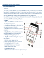
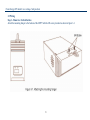
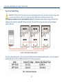
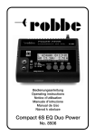
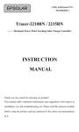
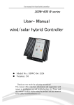
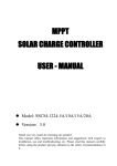
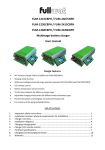
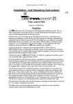
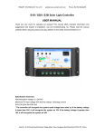
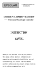
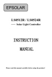
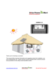
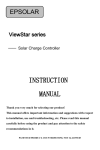
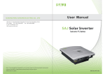
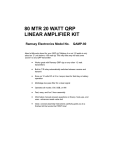
Clean Energy-DIY install- Low voltage- Safe products
User Manual
MPPT Solar charge controller
Energy charged in battery
30%
than conventional solar charger
SUN-MPPT-3015A
SUN-MPPT-5015A
1
Clean Energy-DIY install- Low voltage- Safe products
2
Clean Energy-DIY install- Low voltage- Safe products
List:
Dimensions in Millimeters [Inches] ............................................................................................................................................... 4
1.0 Important Safety Information ................................................................................................................................................... 5
2.0 General Information ................................................................................................................................................................. 6
2.1 Overview ......................................................................................................................................................................... 6
2.2 Features ........................................................................................................................................................................... 6
3.0 Installation ................................................................................................................................................................................ 7
3.1 General Information ........................................................................................................................................................ 7
3.2 Wiring.............................................................................................................................................................................. 8
4.1 MPPT Technology ......................................................................................................................................................... 14
4.2 Battery Charging Information ....................................................................................................................................... 17
4.3 LED Indications ............................................................................................................................................................ 17
4.4 Setting operation ........................................................................................................................................................... 19
5.0 Warranty ................................................................................................................................................................................. 21
6.0 Specifications ......................................................................................................................................................................... 22
3
Clean Energy-DIY install- Low voltage- Safe products
Dimensions in Millimeters [Inches]
4
Clean Energy-DIY install- Low voltage- Safe products
1.0 Important Safety Information
Save These Instructions
This manual contains important safety, installation and operating instructions for the MPPT solar controller.
The following symbols are used throughout this manual to indicate potentially dangerous conditions or mark important
safety instructions:
WARNING:
Indicates a potentially dangerous condition. Use extreme caution when performing this task.
CAUTION:
Indicates a critical procedure for safe and proper operation of the controller.
NOTE:
Indicates a procedure or function that is important for the safe and proper operation of the controller.
General Safety Information
• Read all of the instructions and cautions in the manual before the beginning of installation.
• MPPT contains no user-serviceable parts.Do not disassemble or attempt to repair the controller.
• Disconnect all sources of power to the controller before installing or adjusting the MPPT.
• There are no fuses or disconnects inside the MPPT. Do not attempt to repair it.
• Install external fuses/breakers as required.
5
Clean Energy-DIY install- Low voltage- Safe products
2.0 General Information
2.1 Overview
Thank you for selecting the MPPT solar charge controller.The MPPT is essentially a smart DC to DC converter which has
been optimized to harvest maximum energy from the PV array in battery based solar electric systems by using a variety of
maximum power point tracking (MPPT) strategies. The controller’s secondary objective is to ensure that the batteries receive
a full charge without becoming overcharged. This is accomplished through a four stage charging process.
Please take the time to read this operator’s manual and be familiar with the controller.This will help you make full use of the
many advantages the MPPT can provide for your PV system.
2.2 Features
1 - Battery Status LED Indicator:An LED indicator that
shows battery status or system errors.
2 - Charging Status LED Insdicator:An LED indicator that
shows charging status and overvoltage of pv.
3 - Setting Button1:Set load work mode,battery type and max
charge current.
4 - Setting Button2:Set load work mode,battery type and max
charge current(in manual mode used for load ON/OFF).
5 - LCD Digital Display:Dispaly the system status
6 - Wiring Box Cover:Sheet metal wiring box cover protects
power connections
7 - FAN:FAN to dissipate Internal circuit heat
8 - Heatsink:Aluminum heatsink to dissipate controller heat
9 - Mounting Hanger:Keyhole slot for mounting
10 - Solar Module Terminals:Connect solar modules
11 - Battery Terminals:Connect batteries
12 - Load Terminals:Connect loads
13 - RJ45 Communication Interface:Communicate with personal computer
6
Clean Energy-DIY install- Low voltage- Safe products
3.0 Installation
3.1 General Information
The mounting location is important to the performance and operating life of the controller. The environment must be dry and
protected from water ingress. If required, the controller may be installed in a ventilated enclosure with sufficient air flow.
Never install the MPPT unit in a sealed enclosure. The controller may be mounted in an enclosure with sealed batteries, but
never with vented/ flooded batteries. Battery fumes from vented batteries will corrode and destroy the MPPT circuits.
Multiple MPPT can be installed in parallel on the same battery bank to achieve higher charging current. Additional parallel
controllers can also be added in the future. Each MPPT must have its own solar array.
CAUTION: Equipment Damage or Risk of Explosion
Never install the MPPT in an enclosure with vented/Flooded batteries. Battery fumes are fl ammable and will
corrode and destroy the MPPT circuits.
CAUTION: Equipment Damage
When installing the MPPT in an enclosure, ensure suffi cient ventilation. Installation in a sealed enclosure will lead
to over-heating and a decreased product lifetime.
NOTE : Mounting
When mounting the MPPT ,ensure free air through the controller heat sink fins. There should be at least 150mm of
clearance above and below the controller to allow for cooling. If mounted in an enclosure, ventilation is highly
recommended.
7
Clean Energy-DIY install- Low voltage- Safe products
3.2 Wiring
Step 1 - Mount to a Vertical Surface
Attach the mounting hanger to the bottom of the MPPT with the M6 screw provided as shown in figure 3-1.
8
Clean Energy-DIY install- Low voltage- Safe products
2. Place the MPPT on a vertical surface protected from direct sunlight, high temperatures, and water. The MPPT requires at
least 150 mm of clearance right and left. flow as shown in figure 3-2 below.
9
Clean Energy-DIY install- Low voltage- Safe products
Step 2: DC load Wiring (Refer to Fig.3-3)
WARNING:Please use the appropriate cable size according to load rating. Please refer to important Safety Warnings
Section for the details. It will prevent internal high temperature.
The load output will provide battery voltage to connected loads such as lights,monitors and other electronic devices.
● connect load positive(+) wire to the positive terminal of the unit and load negative(-) wire to the negative terminal of the
unit.
● install a DC Breaker or a DC fuse holder in a positive wire. The rating of the DC Breaker/Fuse must be rated to 125% of
the maximum load current or more. Keep the DC breaker off or do not install the DC fuse.
● See Section 4.3 Setting Operation for more detials about load control.
Step 3: Battery Wiring (Refer to Fig.3-4)
WARNING: Risk of explosion or fire ! Never short circuit positive(+) and negative(-) or cables
● connect battery positive(+) wire to the positive terminal of the unit and battery negative(-) wire to the negative terminal of
the unit. Use #6 to #7 AWG wire rated for 75ºC for Battery connections.
● install a DC Breaker or a DC fuse holder in a positive wire. The rating of the DC Breaker/Fuse must be rated to 125% of
the maximum charging current or more. Keep the DC breaker off or do not install the DC fuse.
1) Multiple batteries in series connection (Refer to Fig.3-5): All batteries must be equal in voltage and amp hour capacity.
The sum of their voltage must be equal to the nominal DC Voltage of the unit.
2) Multiple batteries in parallel connection(Refer to Fig.3-6): Each battery’s voltage must be equal to the Nominal DC
Voltage of the unit.
10
Clean Energy-DIY install- Low voltage- Safe products
11
Clean Energy-DIY install- Low voltage- Safe products
Step 4: Solar Module Wiring
WARNING: Risk of electric shock! Exercise caution when handing solar wiring. The solar array high voltage output
can cause severe shock or injury. Cover modules form the sunlight before installing solar panel wiring.
1) Multiple solar modules in series connection(Refer to Fig.3-7): All modules must be equal in voltage.The sum if their
voltage must be equal to the nominal DC Voltage of the unit. The sum of their solar power must exceed the maximum
capacity of the unit.
● connect soalr module positive(+) wire to the positive terminal of the unit and soalrmodule negative(-) wire to the negative
terminal of the unit. Use #6 to #7 AWG wirerated for 75ºC for Solar connections.
12
Clean Energy-DIY install- Low voltage- Safe products
2) Multiple solar modules in parallel connection(Refer to Fig.7): Each module’s voltage must be equal to the nominal DC
Voltage of the unit. The sum of their solar power must exceed the maximum capacity of the unit(see below Table 3-1)
Step 5: Switch on DC breaker or install DC fuse
After completing all wires,double check if all wires are connected well. Then switch on DC breaker or install DC fuse on.
Take off the cover of solar module. When the solar module power is above 15V, the charge will automatically turn on to work.
13
Clean Energy-DIY install- Low voltage- Safe products
4.0 Operation
The MPPT operation is fully automatic. After installation is completed, there are few operator tasks to perform. However,
the operator should be familiar with the operation and care of the MPPT as described in this section.
4.1 MPPT Technology
MPPT stands for "Maximum Power Point Tracking". This describes a process by means of which the solar module is always
operated at the point of maximum possible power. Because the point the maximum power can vary depending on the
operating mode and the local conditions, and because it changes in the course of the day, the term "tracking" is used, i.e. the
tracking of this point.
Current Boost
Under most conditions, MPPT technology will “boost” the solar charge current. For example, a system may have 36 Amps
of solar current flowing into the MPPT and 44 Amps of charge current flowing out to the battery.The MPPT does not create
current! Rest assured that the power into the MPPT is the same as the power out of the MPPT. Since power is the product of
voltage and current (Volts x Amps), the following is true*:
(1) Power Into the MPPT = Power Out of the MPPT
(2) Volts In x Amps In = Volts Out x Amps Out
* assuming 100% efficiency. Losses in wiring and conversion exist.
If the solar module’s maximum power voltage (Vmp) is greater than the battery voltage, it follows that the battery current
must be proportionally greater than the solar input current so that input and output power are balanced. The greater the
difference between the Vmp and battery voltage, the greater the current boost. Current boost can be substantial in systems
where the solar array is of a higher nominal voltage than the battery.
An Advantage Over Traditional Controllers
Traditional controllers connect the solar module directly to the battery when recharging. This requires that the solar module
operate in a voltage range that is usually below the module’s Vmp. In a 12 Volt system for example, the battery voltage may
range from 10 - 15 Vdc, but the module’s Vmp is typically around 16 or 17 Volts.
Figure 4-1 shows typical current vs. voltage and power output curves for a nominal 12 Volt off-grid module.
14
Clean Energy-DIY install- Low voltage- Safe products
The array Vmp is the voltage where the product of output current and voltage (Amps x Volts) is greatest, which falls on
the “knee” of the solar module I-V curve as shown on the left in Figure 4-1.
Because traditional controllers do not always operate at the Vmp of the solar array, energy is wasted that could otherwise
be used to charge the battery and power system loads. The greater the difference between battery voltage and the Vmp of
the module, the more energy is wasted. MPPT technology will always operate at the maximum power point resulting in
less wasted energy compared to traditional controllers.
Conditions That Limit the Effectiveness of MPPT
The Vmp of a solar module decreases as the temperature of the module increases. In very hot weather, the Vmp may be close
or even less than battery voltage. In this situation, there will be very little or no MPPT gain compared to traditional
controllers. However, systems with modules of higher nominal voltage than the battery bank will always have an array Vmp
greater than battery voltage. Additionally, the savings in wiring due to reduced solar current make MPPT worthwhile even in
hot climates.
15
Clean Energy-DIY install- Low voltage- Safe products
Equalize Stage
WARNING: Risk of Explosion
Equalizing vented batteries produces explosive gases. The battery bank must be properlyventilated.
CAUTION: Equipment Damage
Equalization increases the battery voltage to levels that may damage sensitive DC loads. Verifyall system loads are
rated for the temperature compensated Equalize voltage before beginning an Equalization charge.
CAUTION: Equipment Damage
Excessive overcharging and gassing too vigorously can damage the battery plates and cause shedding of active
material from the plates. An equalization that is too high or for too long can be damaging. Review the requirements
for the particular battery being used in your system.
Certain types of batteries benefit from periodic equalizing charge, which can stir the electrolyte,balance battery voltage and
complete chemical reaction. Equalizing charge increases the battery voltage, higher than the standard complement voltage,
which gasifies the battery electrolyte.
If it detects that the battery is being over discharged, the solar controller will automatically turn the battery to equalization
charging stage, and the equalization charging will be 120mins. Equalizing charge and boost charge are not carried out
constantly in a full charge process to avoid too much gas precipitation or overheating of battery.
16
Clean Energy-DIY install- Low voltage- Safe products
4.2 Battery Charging Information
4-Stage Charging
The MPPT has a 4-stage battery charging
algorithm for rapid, effcient, and safebattery
charging. Figure 4-2 shows the sequence of
the stages.
Bulk Charge Stage
In Bulk charging stage, the battery is not at
100% state of charge and battery voltage has
not yet charged to the Absorption voltage
setpoint. The controller will deliver 100% of
available solar power to recharge the battery.
Absorption Stage
When the battery has recharged to the Absorption voltage setpoint, constant-voltage regulation is used to maintain battery
voltage at the Absorption setpoint. This prevents heating and excessive battery gassing. The battery is allowed to come to
full state of charge at the Absorption voltage setpoint.
The Absorption setpoint is temperature compensated if the RTS is connected.
Float Stage
After the battery is fully charged in the Absorption stage, the MPPT reduces the battery voltage to the Float voltage setpoint.
When the battery is fully recharged, there can be no more chemical reactions and all the charging current is turned into heat
and gassing. The float stage provides a very low rate of maintenance charging while reducing the heating and gassing of
afully charged battery. The purpose of float is to protect the battery from long-term overcharge.
The Float setpoint is temperature compensated if the RTS is connected.
4.3 LED Indications
● Charging Indicator
The green LED indicator will light whenever sunlight is available for battery charging, the green charging LED will stay on in
normal charging. The charging LED indicator flashes when PV over voltage.
17
Clean Energy-DIY install- Low voltage- Safe products
Charging LED Indicator
Color
Green
Green
Table4-1
Indication
On solid
Flashing
Operating Status
Charging
PV over-voltage
● Battery Indicator
GREEN ON
when battery voltage in normal range
ORANGE ON
when battery under voltage
RED ON
when battery over discharged
Battery LED Indicator
Color
Green
Orange
Red
Red
Table4-2
Indication
On solid
On solid
On solid
Flashing
Operating Status
Normal(battery)
Under voltage(battery)
Over diacharged(battery)
Short circuit(load)
● PV Overvoltage indicators
if the solar input open voltage(Voc) exceeds the maxmum rating. the array will remain disconnected until the Voc fails safely
below the maximum rating.
PV over-voltage LED Indicator
Color
Green
Table4-3
Indication
Flashing
Operating Status
PV over-voltage
● Load indicators
When the load amp is1.25 timers of rated current for 60seconds, or the load amp is 1.5 timers of rated current for 5
secends(overload); or load short circuit, the Battery Indicator RED flashing and the LCD load icon flashing.
Load LED Indicator
Color
Red
Table4-4
Indication
Flashing LCD load icon flashing
18
Operating Status
Overload or Short circuit
Clean Energy-DIY install- Low voltage- Safe products
4.4 Setting operation
There are 4 parameters can be set in Load Work Setting Mode:
1F(Optical delay),2F(Optical),3F(Battery type),4F(Maximum
charging current)
Press “KEY 1”hold for 3 seconds enters the setting mode, then press KEY 1, the LCD will switch over between
1F,2F,3F,4F.Press KEY 2,when “ ”appears on LCD indicate enters current mode. Then press “+(KEY1)”“-(KEY2)”to set. If you
don’t need to set up other programs just leave the button alone for 5 seconds to exit set mode. If you need to achieve other
settings, please press the set key for 2 seconds come back to whole set mode. Then press “KEY 1”, the LCD will switch over
between 1F,2F,3F,4F, press KEY 2 to enter option mode to set.
● Load Control Setting(Setting Mode 1F00 and 2F00)
1. Dusk to Dawn (Light ON + Light OFF)
When solar module voltage goes below the point of NTTV (Night Time Threshold Voltage) at sunset, the solar controller will
recognize the starting voltage and turn on the load after 10 minutes delay; When solar module voltage goes above point of
DTTV (Day Time ThresholdVoltage), the solar controller will recognize the starting voltage and turn off the load after 10
minutes delay.
2. Light ON + Timer (1-15h on)
When solar module voltage goes below the point of NTTV (Night Time Threshold Voltage) at sunset; the solar controller will
19
Clean Energy-DIY install- Low voltage- Safe products
recognize the starting voltage and turn on the load after 10 minutes delay for several hours which users set on the timer. The
timer setting operation is referred to as “Load Work Mode Setting”.
3. Test Mode
It is used to test the system and the same as Dusk to
Dawn. But there is no 10 minutes delay when controller
recognizes the starting voltage. When below the starting
voltage, the controller will turn on the load, if higher, it
will turn off load. The test mode makes it easy to check
the system installation.
4. Manual Mode
This mode is to turn on/off the load by Setting Switch.
● Battery Setting(Setting Mode 3FB1)
Battery type
LCD dispaly
Sealed lead acid battery
3Fb1
Gel battery
3Fb2
AGM battery
3Fb3
Flooded battery
3Fb4
● Maximum charging Setting(Setting Mode 3FB1)
The default maximum charging current is 50A,customers
can set the maximum charging current depend on
themselves requirement. Range 10-50 Amps.
Time
Disable
Load will be on for 1 hour after ten minutes delay since sunset
Load will be on for 2 hour after ten minutes delay since sunset
Load will be on for 3 hour after ten minutes delay since sunset
Load will be on for 4 hour after ten minutes delay since sunset
Load will be on for 5 hour after ten minutes delay since sunset
Load will be on for 6 hour after ten minutes delay since sunset
Load will be on for 7 hour after ten minutes delay since sunset
Load will be on for 8 hour after ten minutes delay since sunset
Load will be on for 9 hour after ten minutes delay since sunset
Load will be on for 10 hour after ten minutes delay since sunset
Load will be on for 11 hour after ten minutes delay since sunset
Load will be on for 12 hour after ten minutes delay since sunset
Load will be on for 13 hour after ten minutes delay since sunset
Load will be on for 14 hour after ten minutes delay since sunset
Load will be on for 15 hour after ten minutes delay since sunset
Test mode
ON/OFF mode
Table 4-5
20
Load work mode
Digital No.
0
1
2
3
4
5
6
7
8
9
10
11
12
13
14
15
16
17
Clean Energy-DIY install- Low voltage- Safe products
5.0 Warranty
The MPPT charge controller is warranted to be free from defects in material and work-manship for a period of TWO(2) years
from the date of shipment to the original end user. We will, at its option, repair or replace any such defective products.
CLAIM PROCEDURE
Before requesting warranty service, check the Operator’s Manual to be certain that there is a problem with the controller. Return
the defective product to us with shipping charges prepaid. Provide proof of date and place of purchase. To obtain service under
this warranty, the returned products must include the model, serial number and detailed reason for the failure, the module type,
array size, type of batteries and system loads. This information is critical to a rapid disposition of your warranty claim.
WARRANTY EXCLUSIONS AND LIMITATIONS
This warranty does not apply under the following conditions:
• Damage by accident, negligence, abuse or improper use.
• PV or load currents exceeding the ratings of the product.
• Unauthorized product modification or attempted repair.
• Damage occurring during shipment.
• Irreclaimable mechanical damage.
21
Clean Energy-DIY install- Low voltage- Safe products
6.0 Specifications
Electrical
Battery Charging
Charging algorithm
Charging stages
Absorption, Float, Equalize
Temperature compensation coeffcient
cell (25 °C ref.)
Temperature compensated setpoints
Float, Equalize, HVD
Charging Setpoints:
NOTE:
All charging voltage setpoints listed are for 12 Volt systems.
Multiply 2X for 24 Volt systems.
22
4 - stage
Bulk,
-5 mV / °C /
Absorption,
Clean Energy-DIY install- Low voltage- Safe products
23
Clean Energy-DIY install- Low voltage- Safe products
24