1
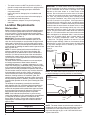
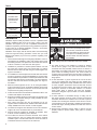
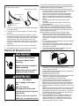
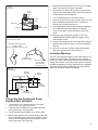
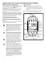
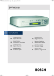
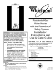
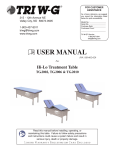
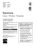
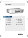
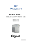
Residential Electric
Heat Pump Water Heater
Installation
Instructions and
Use & Care Guide
To obtain technical, warranty or service assistance during or after
the installation of this water heater, call toll free
1-877-817-6750
When calling for assistance, please have the following
information ready:
1. Model number
2. 7 Digit product number
3. Serial number
4. Date of installation
5. Place of Purchase
Table of Contents Page
Water Heater Safety ................................................................................ 2
Installing Your Water Heater .................................................................. 3-9
Consumer Information ................................................................. 3
Consumer Responsibilities .......................................................... 3
Unpacking Instructions ............................................................. 3-4
Location Requirements ................................................................ 4
Confined Space Installation.......................................................5-6
Water System Piping................................................................. 7-8
Temperature & Pressure Relief Valve...................................... 9-10
Electrical Requirements ........................................................ 10-11
Installation Checklist ............................................................................... 12
Operating Your Water Heater ............................................................ 13-15
Before Using .............................................................................. 13
Water Temperature Regulation .................................................. 13
Adjusting the User Interface Module/ Operational Mode ........... 14
Operational Conditions .............................................................. 15
Maintenance of Your Water Heater ................................................... 16-17
Temperature and Pressure Relief Valve..................................... 16
Draining and Flushing................................................................. 16
Heating Element Replacement.............................................. 16-17
Cleaning the Heat Pump............................................................ 17
Diagnostic Codes ................................................................................... 18
Troubleshooting Chart ............................................................................ 19
Repair Parts Illustration .......................................................................... 20
Notes..................................................................................................21-22
317252-002
April 2012
1
WATER HEATER SAFETY
Your safety and the safety of others are very important.
We have provided many important safety messages in this manual and on your appliance. Always read and obey all
safety messages.
This is the safety alert symbol.
This symbol alerts you to potential hazards that can kill or hurt you and others.
All safety messages will follow the safety alert symbol and either the word “DANGER” or
“WARNING.” These words mean:
You can be killed or seriously injured if you don’t
immediately follow instructions.
You can be killed or seriously injured if you don’t
follow instructions.
All safety messages will tell you what the potential hazard is, tell you how to reduce the chance of injury, and tell you
what can happen if the instructions are not followed.
Important Safety Instructions
CAUTION: Hydrogen gas is produced in a hot water system served by this heater that has not been used for a long
period of time (2 weeks or more). Hydrogen gas is extremely flammable. To reduce the risk of injury under these
conditions, it is recommended that the hot water faucet be opened for several minutes at the kitchen sink before
using any electrical appliance connected to the hot water system. When hydrogen is present, there will probably be
an unusual sound such as air escaping through the pipe as the water begins to flow. There should be no smoking or
open flame near the faucet at the time it is open.
The California Safe Drinking Water and Toxic Enforcement Act requires the Governor of California to publish a list of
substances known to the State of California to cause cancer, birth defects, or other reproductive harm, and requires
businesses to warn of potential exposure to such substances.
WARNING: This product contains a chemical known to the State of California to cause cancer, birth defects, or other
reproductive harm.
This appliance can cause low-level exposure to some of the substances included in the Act.
IMPORTANT: The heat pump portion of this water heater uses R-134a refrigerant. See the data plate on the heat pump
jacket for the charge level.
2
INSTALLING YOUR WATER HEATER
Consumer Information
This water heater should be installed in accordance with
the local code authority having jurisdiction, the power
company or electric utility, and this installation manual.
In the absence of local code requirements, follow the
regulations set forth in the latest edition of The National
Electric Code, NFPA 70. This is available from the
following:
National Fire Protection Association
1 Batterymarch Park
Quincy, MA 02269
American National Standards Institute
1430 Broadway
New York, NY 10018
Check your phone listings for the local authorities having
jurisdiction over your installation.
Consumer Responsibilities
This manual has been prepared to acquaint you with the
installation, operation and maintenance of your electric heat
pump water heater and to provide important safety information
in these areas.
We urge you to read all of the instructions thoroughly before
attempting the installation or operation of this water heater.
This manual should be kept for future reference.
The manufacturer of this water heater will not be liable for any
damages caused by failure to comply with the installation and
operating instructions outlined in this manual.
If you lack the necessary skills required to properly install this
water heater or you have difficulty following the directions, you
should not proceed but have a qualified person perform the
installation of this water heater.
Examples of a qualified person include: licensed plumbers,
authorized electric company personnel, and authorized
service personnel.
Massachusetts code requires this water heater to be installed
in accordance with Massachusetts 248-CMR 2.00: State
Plumbing Code and 248-CMR 5.00.
A data plate identifying your water heater can be found
adjacent to the upper element door. When referring to your
water heater always have the information listed on the data
plate readily available, to include the model and serial number.
Retain your original receipt as proof of purchase.
Basic Operation Fundamentals
The Heat Pump Water Heater (HPWH) is an integrated
heat pump water heater unit, having an 850 watt
compressor and external coil heat exchanger with backup
electric elements (See Figure 1). When in Efficiency Mode
the heat pump draws heat from the ambient air in the room
and transfers it to the water in the tank through the coil
heat exchanger. While in Electric Mode the water heater
functions like a standard electric water heater, relying on
the electric elements to heat the water. A Hybrid Mode is
available that relies primarily on the heat pump to heat
the water while the electric elements only function during
high demand periods. (See “Adjusting the User Interface
Module/ Operational Mode” section). The more often
the unit operates using the heat pump, rather than the
elements, the more efficient the unit will be.
The tank capacity of this heat pump water heater is sized to
maximize the use of the heat pump to deliver hot water at
a lower cost as compared to heat pump waters with lower
tank capacities (50 gallons or less.)
The HPWH uses about half the electricity of a comparably
sized conventional electric water heater when operating
in the Efficiency Mode, and provides up to ½ ton cooling
capacity and dehumidification. It is designed for indoor,
residential applications for installation in a basement,
garage or utility room (See “Location Requirements”
section).
Figure 1
Heat Pump Water Heater Basic Operation
Cool/Dehumidified Air
Ambient Air
Heat Pump
(Transfers heat
from ambient
air to Heat
Exchanger)
Upper Element
(4500 Watt)
Water Tank
Jacket
Heat Exchanger
(Heat Transfer Coils)
Lower Element
(2000 Watt)
Unpacking the Water Heater
WARNING
Excessive Weight Hazard
Use two or more people to move and install
water heater.
Failure to do so can result in back or
other injury.
Removing Packaging Materials
IMPORTANT: Do not remove, cover or deface any
permanent instructions, labels, or the data label from either
the outside of the water heater or on the inside of water
heater panels.
3
•
•
•
•
•
The water heater must NOT be placed on its side. It
should be transported and stored in an upright position.
Remove exterior packaging and place installation
components aside.
Inspect all parts for damage prior to installation and
start-up.
Completely read all instructions before attempting to
assemble and install this product.
After installation, dispose of/recycle all packaging
materials.
Location Requirements
Site location
Select a location near the center of the water piping system.
The unit must be installed indoors and in a vertical position
on a level surface. The flooring beneath the water heater
must be able to support the weight of the water heater when
filled with water (See Table 1).
IMPORTANT: The water heater must have unresticted
airflow and requires a minimum installation space of 750
cubic feet. As an example, a room that has an eight foot tall
ceiling and is 10 feet long by 9-1/2 feet wide would contain
760 cubic feet. See The Confined Space Installation section
of this manual for installing the water heater in spaces of less
than 750 cubic feet.
NOTE: To ensure optimal performance and efficiency a
minimum clearance of six (6) inches from the back, left
and right sides of the water heater must be maintained. A
minimum of 12 inches from the front of the unit should be
maintained for control access. Service clearances of three
(3) feet from the left and right sides are recommended as a
best installation practice.
The water heater should be located in an area not subject
to freezing temperatures. Water heaters located in
unconditioned spaces (i.e., garages, basements, etc.) may
require the water piping, condensate piping, and drain piping
to be insulated to shelter against freezing. The drain and
controls must be easily accessible for operation and service.
The site location must be free from any corrosive elements
in the atmosphere such as sulfur, fluorine, and chlorine.
These elements are found in aerosol sprays, detergents,
bleaches, cleaning solvents, air fresheners, paint, and
varnish removers, refrigerants, and many other commercial
and household products. In addition, excessive dust and lint
may affect the operation of the unit (See “Cleaning the Filter”
section).
The ambient air temperature must also be considered
when installing this unit. In Efficiency Mode the ambient air
temperature must be above 45°F and below 109°F. If the
ambient air temperature falls outside these upper and lower
limits the electrical elements will activate to meet the hot
water demand and the heat pump does not operate.
NOTE: Local codes and requirements in your area may
require the installation of your water heater be accomplished
in a way that the bottom element is elevated from the
floor at least 18 inches. Ensure that a platform capable of
supporting the combined weight of the water heater and
water is used.
Table 1
4
Capacity
Weight (lbs)
60 Gallon
760
80 Gallon
967
IMPORTANT: The water heater should be located in an
area where leakage of the tank, connections, condensate
lines or condensate will not result in damage to the area
adjacent to the water heater or to lower floors of the
structure. Due to the normal corrosive action of the water,
the tank will eventually leak after an extended period of
time. Also, any external plumbing leak, including those
from improper installation, may cause early failure of the
tank due to corrosion if not repaired. If the homeowner is
uncomfortable with making the repair a qualified person
should be contacted. A suitable metal drain pan should be
installed under the water heater as shown below, to help
protect the property from damage which may occur from
condensate formation or leaks in the piping connections
or tank. The pan must limit the water level to a maximum
depth of 2-1/2 inches and be two inches wider than the
heater and piped to an adequate drain. Locate the water
heater near a suitable indoor drain. Outside drains are
subject to freezing temperatures which can obstruct
the drain line. The piping should be at least 3/4” ID and
sloped for proper drainage. Under no circumstance will the
manufacturer or seller of this water heater be held liable
for any water damage which is caused by your failure to
follow these instructions.
Figure 2
Metal Drain Pan
Installation
METAL
DRAIN
PAN
PIPED TO AN
ADEQUATE DRAIN
AT LEAST 2” GREATER THAN THE
DIAMETER OF THE WATER HEATER.
NOTE: The water heater shall be located so it is not subject
to physical damage by moving vehicles or area flooding.
Figure 3
Residential Garage
Installation
Vehicle
Stop
Drain
Pan
Drain
State of California
NOTE: The water heater must be braced, anchored, or
strapped to avoid moving during an earthquake. Contact
local utilities for code requirements in your area, visit
http://www.dsa.dgs.ca.gov, or call 1-916-445-8100 and
request instructions.
Confined Space Installation
The heat pump water heaters covered in this manual require a minimum of 750 cubic feet of installation space. When a space
meeting this minimum requirement is not available these units may be installed in spaces with less than 750 cubic feet (confined
spaces) when provisions are made by installing an accessory Outlet Duct Kit and/or louvered grills as described in this section.
Inlet air will be derived from an alternate location inside the building structure through one or more louvered grills or through a fully
louvered door leading into the confined space. The alternate location from where inlet air will be derived must provide a minimum of
750 cubic feet of space when using this installation method. When the Outlet Duct Kit is installed outlet air from the unit is redirected
to an alternate location. The alternate location to where outlet air will be redirected must also provide a minimum of 750 cubic feet
of space.
Other configurations are possible when using the Outlet Duct Kit (PN 9910006000) and/or the Inlet Duct Kit (PN 9910005000) with
these water heaters. Consult the installation instructions included with the duct kits for additional information. These instructions
are also available on the manufacturer’s web site. Contact the distributor where the water heater was purchased for information on
ordering these duct kits.
AIR FLOW
EXTEND DUCT
ABOVE INSULATION
IN ATTIC SPACES
BOOT/COLLAR
CONFINED
SPACE
AIR FLOW
DUCT
TERMINATION
OR GRILL
8 INCH
FLEXIBLE
DUCT
BOOT/COLLAR
AIR FLOW
OUTLET DUCT
KIT ADAPTER
LOUVERED
GRILLS
MINIMUM
16” X 24”
AIR FLOW
FIGURE 4
5
Table 2
ITEM
WITHOUT DUCTWORK
WITH 8 INCH FLEXIBLE DUCT
AND OUTLET DUCT KIT
LOUVERED GRILL
CONFINED SPACE
CONFIGURATION
(door or wall)
MINIMUM SPACE
(cubic feet)
610
460
400
128
EXAMPLE ROOM SIZE
H X L X W (feet)
8' x 7.6' x 10'
8' x 5.75' x 10'
8' x 10' x 5'
8' x 4' x 4'
Installation
Installation requires ability equivalent to that of a qualified HVAC
installer. Installation skills such as air supply, venting, and duct
installation are required. If you are not qualified and licensed or
certified as required by the authority having jurisdiction to perform
a given task do not attempt installation. Contact a local HVAC
contractor to perform the installation.
Installation must comply with all national, state and local building
codes and agencies having jurisdiction. Check with your local
building code authority if you have any questions regarding code
compliance.
1. Inlet air is derived through louvered grill(s) installed in a door or
wall between the installation space and another space inside
the building structure. The space from where inlet air is derived
must be a minimum of 750 cubic feet. See Figure 4.
2. Installation is permitted in confined spaces between 750 and
610 cubic feet of space using one louvered grill or in spaces
between 610 and 460 cubic feet using two louvered grills. See
Figure 4 and Table 2.
3. For installation in confined spaces of less than 460 cubic feet the
accessory Outlet Duct Kit (PN 9910006000) is required. With
this kit installation is permitted in confined spaces between 460
and 400 cubic feet with one louvered grill or in spaces between
400 and 128 cubic feet with two louvered grills. See Figure 4
and Table 2.
4. Minimum louvered grill size is 16” x 24” for each grill installed.
Fully louvered doors are an acceptable substitute for louvered
grill(s) if the louvered area of the door is not less than the total
required area the grill(s) would provide.
5. Follow the instructions included with the Outlet Duct Kit for the
included duct adapter and ductwork.
6. Eight (8) inch flexible ducting is required but not supplied in the
Outlet Duct Kit. Suitable ducting is readily available at home
centers or HVAC supplies.
7. Duct collars and boots may also be required but are not
supplied with the Outlet Duct Kit. Suitable collars and boots are
readily available from home centers or HVAC supplies.
8. The maximum length of duct allowed is 10 feet. This maximum
length must not be exceeded under any circumstances.
9. Ducting should be installed as straightly as possible; there
must be no kinks or flattening of the ductwork.
10.The Outlet Duct Kit and connected ductwork must redirect
outlet air from the unit to a location other than the confined
installation space. The alternate location to where the outlet air
is redirected must be a minimum of 750 cubic feet.
6
Breathing Hazard - Carbon Monoxide Gas
Do not duct air from a garage or other
space where potentially harmful fumes
from solvents, chemicals or exhaust
from automobiles are present into any
other space in the building structure.
Gas and carbon monoxide detectors
are available.
Breathing carbon monoxide can cause brain damage or
death. Always read and understand instruction manual.
11. The outlet air from a unit installed in a garage or drawing
inlet air from a garage or any area where solvents or other
chemicals that emit potentially harmful fumes are stored or
automobiles are located must never be ducted to any other
space inside the building structure. This would include all
occupied and unoccupied spaces such as attics or basements.
Potentially harmful fumes and vapors could be introduced into
living spaces.
12.A duct termination or grill is required at the end of the duct
run but not supplied with the Outlet Duct Kit. Suitable duct
terminations and grills are readily available from home centers
or HVAC supplies. Terminations must be fitted with screens
or designed to prevent rodents, other pests and debris from
entering the ductwork. If terminated outdoors or to another
space where water or moisture may enter the ductwork,
terminations designed to prevent water or moisture infiltration
must be used.
13.If outlet ductwork is terminated through a ceiling into an
attic space provision must be made to ensure the ductwork
terminates well above the insulation line in the attic to prevent
insulation from entering the ductwork. A short section of 8 inch
round metal duct may be used with a suitable duct termination.
Overall duct length, including flexible and metal duct must not
exceed 10 feet.
14.Ductwork that transitions through walls or ceilings must be
properly sealed to prevent rodent, other pests or moisture
infiltration.
Water System Piping
Piping, fittings, and valves should be installed according to
the installation drawing (Figure 5). If the indoor installation
area is subject to freezing temperatures, the water piping
must be properly insulated.
Water supply pressure should be 50-60 PSIG and not
exceed the maximum 80 PSIG. If the supply line pressure
exceeds 80 PSIG, a pressure reducing valve (PRV) with
a bypass should be installed in the cold water supply line.
This should be placed on the supply to the entire house in
order to maintain equal hot and cold water pressures.
IMPORTANT:
• Heat must not be applied to the water fittings on
the heater as they may contain nonmetallic parts. If
solder connections are used, solder the pipe to the
adapter before attaching the adapter to the hot and
cold water fittings.
• Always use a good grade of joint compound and be
certain that all fittings are tight.
IMPORTANT: DO NOT over apply joint compound.
Piping Installation
1. Install the water piping and fittings as shown in Figure
4. Connect the cold water supply (3/4” NPT) to the
fitting marked “Cold”. Connect the hot water supply
(3/4” NPT) to the fitting marked “Hot”.
2. The installation of unions in both the hot and cold water supply lines are recommended for ease of removing the water heater for service or replacement.
3. Some local codes may require, and the manufacturer
of this water heater recommends, installing a mixing
valve or an anti-scald device in the domestic hot water
line as shown in Figure 5. These valves reduce the
point-of-use temperature of the hot water by mixing
cold and hot water and are readily available. Contact
a licensed plumber or the local plumbing authority for
more information.
4. Some local codes may require, and the manufacturer
of this water heater recommends, installing a pressure
reducing valve (PRV) in the cold water inlet line where
it enters the residence as shown in Figure 5.
5. If installing the water heater in a closed water system, install an expansion tank in the cold water line as
specified under “Closed System/Thermal Expansion.”
6. Install a shut off valve in the cold water inlet line. It should be located close to the water heater and be easily accessible. Know the location of this valve and how to shut off the water to the heater.
7. Install a discharge line from the temperature and
pressure relief valve in the opening marked “T & P
RELIEF VALVE”. See Figure 5 and the “Temperature
and Pressure Relief Valve” section.)
8. After piping has been properly connected to the water
heater, open the nearest hot water faucet. Then open
the cold water shut off valve and allow the tank to
completely fill with water. To purge the lines of any
excess air and sediment, keep the hot water faucet
open for 3 minutes after a constant flow of water is
obtained. Close the faucet and check all connections
for leaks.
Massachusetts: Install a vacuum relief in
cold water line per section 19 MGL 142.
Optional Heat Trap Piping
Vacuum Relief Valve
(when required by local code)
Union
Union
Temperature and
Pressure Relief Valve
Shut-off Valve (Hot)
Untempered Water Outlet
Hot
(Outlet)
Mixing Valve - Follow the Mixing Valve’s
Manufacturer’s Installation Instructions.
(Set to 120° F)
Tempered Water to Fixtures
Discharge Pipe
(Do Not Cap or Plug)
Condensate Drain Lines*
Cold Water
Inlet Valve
Cold Water
Inlet
Pressure Reducing Valve (PRV)
should be installed where the water
supply enters the residence.
When installed PRVs create a
closed water system, a thermal
expansion tank must be installed.
Cold Water Outlet
Metal Drain Pan 2 1/2”
Depth Maximum and
2 Inches wider than
the water heater.
Cold
(Inlet)
In a closed system, use a
thermal expansion tank.
See “Closed System/
Thermal Expansion”
section.
Union
Shut-off Valve
(Cold)
Drain Line 3/4”
ID Minimum
Drain
6” Maximum
Air Gap
* If an adequate drain is not available for the condensate drain lines then a condensate pump must be used. DO NOT discharge the condensate drain
lines into the metal drain pan.
7
Please note the following:
• The system should be installed only with piping that is
suitable for potable (drinkable) water such as copper,
CPVC, or polybutylene. This water heater must not be
installed using iron piping or PVC water piping.
• Use only pumps, valves, or fittings that are compatible
with potable water.
• Use only full flow ball or gate valves. The use of valves
that may cause excessive restriction to water flow is
not recommended.
• Use only 95/5 tin-antimony or other equivalent solder.
Any lead based solder must not be used.
• Piping that has been treated with chromates, boiler
seal, or other chemicals must not be used.
• Chemicals that may contaminate the potable water
supply must not be added to the piping system.
Condensate Drain Line Installation
Install two 1/2” PVC discharge lines from the condensate
drains (located on the right side near the back). The lines
should terminate a maximum of six inches above an
adequate drain. Do not discharge the condensate drain
lines into the metal drain pan. If no floor drain is available
or the drain is above the level of the condensate line, a
condensate pump should be installed. These pumps are
available from local distributors.
When installing the drain line, note the following:
•
Plastic pipe or tubing must be used to connect the
condensate drain to a suitable drain or condensate
pump.
•
Condensate drain lines should be installed in
conditioned areas only. Install approved insulation on
the condensate drain lines to prevent condensation
from forming on the outside of the drain lines.
Condensation drain lines installed in areas that are
subject to freezing temperatures should be wrapped
with a nationally recognized/listed heat tape. Install per
manufacturer’s instructions.
•
Do not connect condensate drain lines with other drain
or discharge lines into a single (common) pipe or line.
Each line (condensate drain line, temperature and
pressure relief valve discharge pipe, etc) should be
independently run to an adequate drain.
•
Slope the condensate drain lines toward the inside
floor drain or condensate pump.
•
The condensate drain lines and connections to the
drain piping must comply with all local codes.
•
Use appropriate primer and glue to cement the
condensate drain lines to the heat pump drain pan.
NOTE: The heat pump drain pan is ABS and the two
condensate drain pipes should be PVC.
•
If a condensate pump is installed it should shut off
the heat pump in the event the condensate pump
fails or the float switch in the pump activates (See
“Condensate Pump Installation” section.)
8
Closed System/Thermal Expansion
WARNING
Explosion Hazard
If the temperature and pressure relief valve
is dripping or leaking, have a qualified
person replace it.
Examples of a qualified person include:
licensed plumbers, authorized electric
company personnel, and authorized service
personnel.
Do not plug valve.
Do not remove valve.
Failure to follow these instructions can
result in death or explosion.
Most public water systems in North America are required
to prevent water flowing from points of use (residences,
businesses, etc.) back into the supply system in order
to maintain water quality. To accomplish this, back flow
preventers such as check valves, are installed in the water
line going to each point of use. Typically the back flow
preventer will be installed at the water meter or inside a
building where the supply line enters the building. This
device allows water to flow into the residence but does
not allow it to flow back into the water supply. This creates
what is known as a “Closed System”. As water is heated
by the water heater, the water in the system attempts to
expand, but has nowhere to go resulting in an increase
in pressure. This increase in pressure in the system may
cause the temperature-pressure relief valve to open to
relieve the pressure. Water will drip from the temperature
and pressure relief valve. Premature tank failure will result
if this condition is not corrected. To prevent this condition, a
properly-sized thermal expansion tank should be installed
in the cold water supply to the water heater as shown in
Figure 4. Failure to install a properly sized expansion tank
in a closed system will void the warranty on the water
heater in the event of tank failure. It is important to follow
the thermal expansion tank manufacturers’ installation
instructions and to adjust the expansion tank pressure
to match the water supply pressure. Contact a plumbing
service agency or your retail supplier regarding the
installation of a thermal expansion tank.
Temperature and Pressure
Relief Valve
WARNING
Explosion Hazard
If the temperature and pressure relief valve
is dripping or leaking, have a qualified
person replace it.
Examples of a qualified person include:
licensed plumbers, authorized electric
company personnel, and authorized service
personnel.
Do not plug valve.
Do not remove valve.
Failure to follow these instructions can
result in death or explosion.
Figure 6
Temperature and Pressure
Relief Valve Installation
Temperature and
Pressure Relief Valve
Discharge Pipe
(Do Not Plug or Cap)
Temperature/Pressure Relief Valve and
Pipe Insulation
Drain Pan 2 1/2”
Depth Maximum and
2 Inches wider than
the water heater.
Drain Line 3/4”
ID Minimum
To reduce the risk of excessive pressures and temperatures
in this water heater, install temperature and pressure relief
protective equipment required by local codes, but no less
than a combination temperature and pressure relief valve
certified by a nationally recognized testing laboratory that
maintains periodic inspection of the production of listed
equipment or materials, as meeting the requirements for
Relief Valves and Automatic Shutoff Devices for Hot Water
Supply Systems, ANSI Z21.22 - latest edition. This valve
must be marked with the maximum set pressure not to
exceed the marked maximum working pressure of the
water heater. Install the valve into an opening provided
and marked for this purpose in the water heater, and orient
it or provide tubing so that any discharge from the valve
exits only within 6 inches above drain, or at any distance
below, the structural floor, and does not contact any live
electrical part. The discharge opening must not be blocked
or reduced in size under any circumstance.
IMPORTANT: Only a new temperature and pressure relief
valve should be used with your water heater. Do not use an
old or existing valve as it may be damaged or not adequate
for the working pressure of the new water heater. Do not
place any valve between the relief valve and the tank.
The Temperature & Pressure Relief Valve:
• Shall not be in contact with any electrical part.
• Shall be connected to an adequate discharge line.
• Shall not be rated higher than the working pressure shown on the data plate of the water heater.
The Discharge Line:
• Shall not be smaller than the pipe size of the relief valve or have any reducing coupling installed in the
discharge line.
• Shall not be capped, blocked, plugged or contain any valve between the relief valve and the end of the
discharge line.
• Shall terminate a maximum of six inches above a floor
drain or external to the building. In cold climates, it is
recommended that the discharge pipe be terminated at
an adequate drain inside the building.
• Shall be of material listed for hot water distribution.
• Shall be installed to allow complete drainage of both
the valve and discharge line.
Drain
6” Maximum
Air Gap
For protection against excessive pressures and
temperatures, a temperature and pressure relief valve must
be installed in the opening marked “T & P RELIEF VALVE”
(See Figure 5).
1. Locate the temperature and pressure relief valve on the
water heater (also known as a T&P relief valve). See
Figure 6.
2. Locate the slit running the length of the T&P relief valve
insulation.
3. Spread the slit open and fit the insulation over the T&P
relief valve. See Figure 7. Apply gentle pressure to the
insulation to ensure that it is fully seated on the T&P Relief Valve. Once seated, secure the insulation with duct
tape, electrical tape, or equivalent.
IMPORTANT: The insulation and tape must not block
the discharge opening or hinder access to the manual
relief lever (Figure 7). Ensure a discharge pipe is installed into the T&P valve discharge opening per the
instructions in this manual.
9
Figure 7
T&P Relief Valve Insulation
T&P Relief Valve Insulation
Manual Relief Lever
T&P Relief Valve
T&P Relief Valve
Drain Line
4. Locate the hot water (outlet) & cold water (inlet) pipes
to the water heater.
5. Locate the slit running the length of a section of pipe
insulation.
6. Spread the slit open and slip the insulation over the
cold water (inlet) pipe. Apply gentle pressure along the
length of the insulation to ensure that it is fully seated
around the pipe. Also, ensure that the base of the
insulation is flush with the water heater. Once seated,
secure the insulation with duct tape, electrical tape, or
equivalent.
7. Repeat steps 5 and 6 for the hot water (outlet) pipe.
8. Add additional sections of pipe insulation as needed.
Electrical Requirements
WARNING
If you lack the necessary skills required to properly install the
electrical wiring to this water heater, do not proceed but have a
qualified electrician perform the installation.
When making the electrical connections, always make sure:
• The electrical service provides 240 VAC to the water heater
for proper operation. DO NOT use 208 VAC.
• Wire sizes and connections comply with all applicable
codes or in the absence of local or state codes follow
NFPA-70, the National Electrical Code-current edition.
• Wiring enclosed in approved conduit (if required by local
codes).
• The water heater and electrical supply are properly grounded.
• The electrical supply has the proper overload fuse or
breaker protection.
Figures 9A, 9B & 10 are provided as reference drawings.
Always reference the wiring diagram located on the water
heater for the correct electrical connections and connect the
electrical supply to the water heater in accordance with local
utility requirements and codes.
When installing the electrical wiring to the water heater:
1. Although this water heater is equipped with “Dry Fire”
protection circuitry, be sure tank is completely filled with
water, and all air is purged from the tank before making
any electrical connections. See “Draining and Flushing
Section”.
2. Turn off power to the electrical wiring for the water heater at
the circuit breaker/fuse box.
3. Remove the left louvered access panel (when facing the
water heater) by loosening the screws securing it to the
water heater. See figure 8.
4. Loosen the screws securing the electrical junction box
cover to the water heater and set aside.
Figure 8
Louvered Panel
Electric Shock Hazard
Disconnect power before
servicing.
Replace all parts and panels
before operating.
Failure to do so can result in
death or electrical shock.
WARNING
Fire Hazard
Use 10 gauge solid copper
wire.
Use a UL listed or
CSA approved strain relief.
Connect ground wire to green
ground wire.
Failure to do so can result in
death, fire, or electrical shock.
10
5. Connect the electrical supply to the water heater.
A standard 1/2 inch opening has been made in the junction
box for conduit connections.
6. Connect ground wire to green ground wire in the electrical
junction box of the water heater.
7. Reinstall the junction box cover.
8. Reattach the left louvered access panel to the water heater
and secure it using the screws loosened earlier.
9. Turn on electrical power to the water heater.
10. Press the power button to turn the water heater on, then
press the Efficiency button to set the operating mode.
NOTE: The water heater will conduct a system diagnostic
(approximately 8 minutes) prior to returning to operation.
11. Once the diagnostic sequence has finished, the fan should
turn on.
NOTE: The heat pump’s fan will not turn on if the incoming
water temperature is less than 59 °F and/or the ambient
air temperature is above 109 °F or below 45 °F. Should the
internal diagnostics detect a problem with the heat pump,
an error message will be displayed.
12. Set the operational mode. For standard installation, the
Hybrid Mode offers the best combination of efficiency
and hot water delivery. For detailed descriptions of all
operational modes see “Adjusting the User Interface
Module/Operational Modes” section.
5. Connect these two wires to the two wires on the water
heater using wire nuts or other connectors.
Figure 9A
Junction Box
6. Connect the free ends of the two wires to the shut off
switch on the condensate pump in accordance with the
manufacturers recommendations.
Green
Ground
Wire
7. Turn on electrical power to the water heater.
Ground
Wire
Black Wire
Conduit
(Field Connection)
Red Wire
8. Press the power button to turn the water heater on and
select the desired operational mode. After about 8
minutes, the heat pump will turn on.
9. Test the operation of the shut off switch by unplugging
the condensate pump and filling the condensate
reservoir with water until the float switch opens the
circuit.
10. The heat pump should turn off and the error code
“CONDENSATE DRAIN ALARM “will appear on the
user interface screen.
Figure 9B
Condensate Pump Wiring
11. Plug the condensate pump in and verify that the pump
operates and pumps the water out of the condensate
reservoir.
Condensate Pump Wiring Loop
18 AWG - White
(Loop Located Behind Junction Box)
12. The error on the user interface should clear and the
heat pump should operate after 8 minutes.
Insulation Blankets
White Wires
From Water Heater
Wires to Condensate
Pump Overflow
Shut Off Switch
(18 AWG or Larger)
Figure 10
Wiring Diagram
Overload
Protection
Approved Connectors
Red
The use of an insulation blanket on this water heater is not
needed or recommended. The purpose of an insulation
blanket is to reduce the standby heat loss encountered with
storage tank heaters. Your water heater meets or exceeds
the National Appliance Energy Conservation Act standards
with respect to insulation and standby loss requirements,
making an insulation blanket unnecessary.
Circuit
Breaker
L1
Black
L2
Green
Ground
Wire
To 240v
1 Phase
Power supply
Electrical
Service ground
Connecting the Condensate Pump
Overflow Shut Off Switch
1. Turn off power to the electrical wiring for the water
heater at the circuit breaker/fuse box.
2. Locate the white 18 AWG wire loop behind the field
wiring junction box. See Figure 9B.
3. Cut the loop and strip insulation off of the two ends.
4. Measure the distance from the field wiring junction box
to the condensate pump, and cut two 18 AWG or larger
wires to correct length and strip the insulation at both
ends of each wire. See Figure 9B.
11
INSTALLATION CHECKLIST
Water Heater Location
□□ Centrally located with the water piping system.
□□ The flooring beneath the water heater must be able to
support the weight of the water heater when filled with
water (See Table 1).
□□ Located indoors (such as a basement or garage)
and in a vertical position. Sheltered from freezing
temperatures.
□□ Provisions made to shelter the area from water damage. Metal drain pan installed and piped to an
adequate drain.
□□ Sufficient room to service the water heater.
□□ The water heater must have unrestricted airflow and
requires a minimum installation space of 750 cubic feet.
As an example, a room that has an eight foot tall ceiling
and is 10 feet long by 9-1/2 feet wide would contain
760 cubic feet. See The Confined Space Installation
section of this manual for installing the water heater in
spaces of less than 750 cubic feet.
NOTE: This Heat Pump Water Heater may be located
within a required minimum of 6” clearance from a wall
on the inlet or outlet side, however for future service
considerations a minimum clearance of 3 feet from
any obstruction on the left and right side (air inlet and
outlet) is recommended.
□□ The unit cannot be placed into any type of closet or
small enclosure.
□□ The site location must be free from any corrosive
elements in the atmosphere such as sulfur, fluorine,
and chlorine. These elements are found in aerosol
sprays, detergents, bleaches, cleaning solvents, air
fresheners, paint, and varnish removers, refrigerants,
and many other commercial and household products.
In addition excessive dust and lint may affect the
operation of the unit and require more frequent
cleaning (See “Cleaning the Heat Pump” section).
□□ Ambient air temperature must be above 45°F and
below 109°F. If the ambient air temperature falls
outside these upper and lower limits the electrical
elements will activate to meet the hot water demand.
Water System Piping
□□ Mixing valve (when applicable) installed per
manufacturer’s instructions (See “Water Temperature
Regulation” section).
Condensate Drain Line Installation
□□ Must be located with access to an adequate drain or
condensate pump.
□□ Condensate drain lines installed and piped to an
adequate drain or condensate pump (See Figure 4).
Electrical Connections
□□ This water heater requires a 240 VAC single phase 25
amp power supply. DO NOT use a 208 VAC service.
□□ Wiring size and connections comply with all applicable codes or in the absence of local or state codes follow
NFPA-70, the National Electrical Code-current edition.
□□ Water heater and electrical supply are properly grounded.
□□ Wiring enclosed in approved conduit (if required by
local codes).
□□ Proper overload fuse or circuit breaker protection
installed.
Post Installation Review
□□ Understand how to use the User Interface Module to
set the various modes and functions (See “Adjusting
the User Interface Module/Operating Modes” section).
□□ Hybrid Mode is the recommended Operating Mode.
Understand the various Operating Modes and which
mode may be best based on season, ambient
temperature, and usage (See “Operating Mode
Description” section).
NOTE: It may be necessary to temporarily change
modes if for example filling a spa or hot tub.
□□ Understand the importance of routine inspection/
maintenance of the condensate drain pan and lines
(See “Inspection/Cleaning of the Condensate Drain
Pan & Condensate Drain Lines” section). This is to
help prevent any possible drain line blockage resulting
in the condensate drain pan overflowing.
IMPORTANT: Water coming from the plastic shroud is
an indicator that both condensation drain lines may be
blocked. Immediate action is required.
□□ Temperature and pressure relief valve properly installed with a discharge pipe run to an adequate drain □□ To maintain optimal operation check, remove and clean
the air filter (See “Air Filter Cleaning/Replacement”
and sheltered from freezing (See Figure 5).
section).
□□ All piping properly installed and free of leaks.
□□ The Installation Instructions and Use & Care Guide
□□ Heater completely filled with water (See “Water Piping
should be kept with the water heater for reference.
System” section).
□□ Closed system pressure buildup precautions installed
(See “Closed System/Thermal Expansion” section).
12
OPERATING YOUR WATER HEATER
Before Using
1. Make sure the water heater has been properly installed. See “Installing Your Water Heater” section.
2. Make sure the air filter is correctly seated, as it may
shift during shipping or installation. See “Repair Parts
Illustration” section.
3. Completely fill the tank with water (See “Water Piping”
section).
4. After the water heater tank is completely filled with water,
connect electrical power to the water heater.
5. Read the “Water Temperature Regulation” section of this
manual. If you do not fully understand these instruction,
contact a qualified person.
6. Press the power button (See Figure 11) to turn the water
heater on and allow it to run a system diagnostic. This
typically takes eight minutes. Once complete, proceed to
the next step.
NOTE: If the system diagnostic yields any codes,
reference the Diagnostic Code section in this manual.
7. Adjust the thermostat to the desired temperature
setting as described under “Adjusting the User Interface
Module/Operational Modes” section.
IMPORTANT: Do not attempt to operate this water heater
if the unit has been submerged, subjected to flooding, or
surrounding insulation has been exposed to water in any
way.
Do not attempt to repair a unit subjected to flood conditions.
Water heaters subjected to flood conditions or any time the
unit has been submerged in water require replacement of
the entire water heater.
Safety Shut-off (ECO)
This water heater is designed to automatically shut-off in the
event that the water temperature exceeds 190°F or 87.8°C.
A temperature limit switch or ECO (Energy Cut Off) is used
to shut off the power to the system if the water temperature
exceeds 190°F or 87.8°C (See “Water Temperature
Regulation” section). To reset the ECO disconnect power at
the circuit breaker/fuse box then remove the upper access
panel. Reset the ECO by firmly pushing in the red reset
button located on the ECO block. If the ECO continues
to shut-off the water heater contact a qualified person for
service.
Water Temperature Regulation
WARNING
Water temperature over 125°F can cause
severe burns instantly or death from scalds.
Children, disabled and elderly are at highest
risk of being scalded.
Feel water before bathing or showering.
Temperature limiting valves are available.
The water heater is adjusted to a temperature setting of
no higher than 120°F when it is shipped from the factory.
Water temperature can be regulated by adjusting the User
Interface Module to the preferred setting as shown in
“Adjusting the User Interface Module/Operational Mode”
The preferred starting point is 120°F. There is a hot water
scald potential if the temperature set point is set too high.
IMPORTANT: Adjusting the set point above 120°F on the
User Interface Module will increase the risk of scald injury in
the times shown below.
Table 3
Water
Temperature °F
Time for 1st
Degree Burn
(Less Severe Burns)
Time for
Permanent Burns
2nd & 3rd Degree
(Most Severe Burns)
110
116
116
122
131
140
149
154
(normal shower temp.)
(pain threshold)
35 minutes
1 minute
5 seconds
2 seconds
1 second
instantaneous
45 minutes
5 minutes
25 seconds
5 seconds
2 seconds
1 seconds
(U.S. Government Memorandum, C.P.S.C., Peter L. Armstrong, Sept. 15,1978)
NOTE: During low demand periods when hot water is not
being used, a lower temperature set point will reduce energy
losses and may satisfy your normal hot water needs. If hot
water use is expected to be more than normal, a higher
temperature set point may be required to meet the increased
demand.
When leaving your home for extended periods (vacations,
etc.) set the water heater to Vacation Mode. See “Adjusting the
User Interface Module/Operational Modes” section. This will
maintain the water at low temperatures with minimum energy
losses and prevent the tank from freezing during cold weather.
NOTE: When returning from an extended stay remember to
set the water heater back to the desired Operational Mode.
13
Adjusting the User Interface Module/Operational Modes
Water Temperature Adjustment
Other Controls
The water temperature can be adjusted from 95°F to 150°F.
Use the Up and Down Buttons
on the front
panel to set the desired temperature.
IMPORTANT: Before attempting to adjust the thermostat,
read the “Water Temperature Regulation” section. If the
instructions are not clear, contact a qualified person.
IMPORTANT: Filling a spa or hot tub from this water heater
may result in extended recovery/re-heat time. Switching
(temporarily) to Hybrid Mode or Electric Mode will decrease
the recovery/re-heat time. Be sure to switch back to the
desired operational mode when finished.
Lock - Holding this button for more than 3
seconds switches the lock mode on or off. When
the User Interface Module is locked a symbol
and “Lock” text will be visible on the display (see
Figure 11).
°F/°C
°F/°C - The button switches the display to show
the set temperature in Fahrenheit or Celsius.
Figure 11 User Interface Module
Operational Mode Buttons
Operating Mode Descriptions
The operating modes can be changed by touching the
desired mode icon on the User Interface Module (see
Figure 11.)
NOTE: All buttons on the User Interface are touch sensitive
and require only a light touch to actuate.
HYBRID
EFFICIENCY
ELECTRIC
VACATION
14
Hybrid Mode - This is the default, recommended
setting. Combining high energy efficiency with
reduced recovery time. This mode uses the
heat pump as the primary heating source.
The heating element will heat water if demand
exceeds a predetermined level so that the
set point temperature can be recovered more
quickly.
Efficiency Mode - Is the most energy efficient
mode. This mode uses the heat pump to heat
water in the tank. The elements are not used
unless the ambient operating temperature
is below 45°F or above 109°F. If hot water
demands are not met in Efficiency Mode it may
be necessary to switch to Hybrid Mode.
Electric Mode - The water heater functions as
a conventional electric unit, relying totally on
the elements to heat the water in the tank. This
mode may be useful in winter to eliminate the
output of cold air from the unit.
Vacation Mode - The controller adjusts the
water temperature to approximately 60°F. This
mode is recommended when the water heater
is not in use for a long period of time. This mode
minimizes energy consumption and prevents the
water heater from freezing during cold weather.
NOTE: To activate the Vacation Mode touch the
vacation button. To deactivate Vacation Mode
touch the vacation button. IMPORTANT: The
anode protecting the tank requires power to the
unit to operate. Do not shut off power to the unit
for extended periods of time. If power must be
turned off for an extended period of time, drain
the tank completely.
EFFICIENCY
HYBRID
ELECTRIC
Element
Functioning
Icon
Heat Pump
Functioning
Icon
F
Water
Temperature
Set Point
Water Heater
Mode/Status
Indicator
Water Heater
Efficiency Status
Icon
HEAT PUMP
ELEMENT
°F/°C
Temperature
Up (Increase)
Button
VACATION
LOCK
EFFICIENCY
LCD Control
Panel Lock Icon
Temperature
Down (Decrease)
Button
Fahrenheit/Celsius
LCD Display Panel
Temperature Display
Lock Button
Button
Power Button: On - Green
Standby - Red
Operational Conditions
Powered Anode Operation
To shelter the glass-lined water tank from corrosion
through electrolysis, this water heater is equipped with a
non-sacrificial powered anode which should not need to
be replaced under normal operating conditions. NOTE:
The powered anode operates only when electrical power is
applied.
If the powered anode malfunctions it should be replaced by
a qualified technician.
IMPORTANT: If a faulty powered anode is not repaired or
has been removed permanently, then all warranties are
void.
Water Heater Sounds
During the normal operation of the water heater, sounds or
noises may be heard. These noises are common and may
result from the following:
1. Normal expansion and contraction of metal parts during periods of heat-up and cool-down.
2. Sediment buildup on or around the elements could
create varying amounts of noise and may cause
premature tank failure. Drain and flush the tank as
directed under the “Draining and Flushing” section.
3. The heat pump compressor or fan running.
Stacking
Stacking occurs when a series of short draws of hot water
(3 gallons or less) are taken from the water heater tank.
This causes increased cycling of the heat pump and/
or heater elements and can result in increased water
temperatures at the hot water outlet. An anti-scald device
is recommended in the hot water supply line to reduce the
risk of scald injury.
15
MAINTENANCE OF YOUR WATER HEATER
Temperature and Pressure
Relief Valve
WARNING
Explosion Hazard
If the temperature and pressure relief valve
is dripping or leaking, have a qualified
person replace it.
Examples of a qualified person include:
licensed plumbers, authorized electric
company personnel, and authorized service
personnel.
Do not plug valve.
Do not remove valve.
Failure to follow these instructions can
result in death or explosion.
Manually operate the temperature and pressure relief valve
at least once a year to make sure it is working properly.
To prevent water
Figure 12
damage, the valve
Temperature and Pressure
must be properly
Relief Valve
connected to a
Manual Relief
discharge line which
Valve
terminates at an
adequate drain.
Standing clear of the
outlet (discharged
water may be
hot), slowly lift and
release the lever
Discharge line to drain
handle on the
temperature and
pressure relief valve to allow the valve to operate freely and
return to its closed position. If the valve fails to completely
reset and continues to release water, immediately
disconnect the electrical power, close the cold water inlet
valve and call a qualified person.
Draining and Flushing
It is recommended that the tank be drained and flushed
every 6 months to remove sediment which may build up
during operation. The water heater should be drained if
being shut down during freezing temperatures. To drain the
tank, perform the following steps:
16
1. Place the water heater in Standby Mode by pressing
the power button on the user interface module.
2. Turn off the power to the water heater at the circuit
breaker/fuse box.
3. Open a nearby hot water faucet until the water is no
longer hot.
4. Close the cold water inlet valve.
5. Connect a hose to the drain valve and terminate it to an
adequate drain or external to the building.
6. Open the water heater drain valve and allow all of the
water to drain from the tank. Flush the tank with water
as needed to remove sediment.
7. Close the drain valve, refill the tank (open the cold
water inlet valve), and restart the heater as directed in
this manual.
IMPORTANT: Do not turn on power to the water heater
unless it is completely filled with water. To ensure that
the tank is full, open a hot water faucet and allow the
water to run until the air is purged and the water flows
uninterrupted from the faucet.
8. Press the power button to turn the water heater on.
NOTE: The water heater will conduct a system
diagnostic prior to operation.
If the water heater is going to be shut down for an extended
period, the drain valve should be left open.
Heating Element Replacement
WARNING
Electric Shock Hazard
Disconnect power before
servicing.
Replace all parts and panels
before operating.
Failure to do so can result in
death or electrical shock.
Replacement heating elements must be of the same style
and voltage/wattage rating as the ones originally in the water
heater. This information can be found on the flange or terminal
block of the element or on the water heater data plate.
IMPORTANT: Before replacing any element confirm that
you have the correct replacement element (wattage). This
water heater has a 4500 watt upper element and a 2000
watt lower element. DO NOT replace the element(s) with a
wattage different than the ones specified for the upper and/
or lower element.
IMPORTANT: Using an element greater than 2000 watts
in place of the lower element will damage the water heater
and void the warranty.
1. Press the power button on the user interface module to
place the water heater in Standby Mode.
2. Turn off the power to the water heater.
3. Drain the water heater as directed in the “Draining and Flushing” section.
Routine Preventive Maintenance
Figure 13
Wires
Element
Screws
4. Remove the access cover(s), then remove the foam
insulation block.
5. Remove the protective plastic cover(s) over the
elements from their attachment point. 6. Disconnect the electrical wires from the heating
element(s) by loosening the screws (Figure 13).
Remove the screw-in element(s) by turning the
element(s) counterclockwise with a 1-1/2 inch socket
wrench. Remove the existing gasket(s).
7. Clean the area where the gasket(s) fits to the tank
and internal threads. If you are replacing the bottom
element, remove any accumulated sediment on the
bottom of the tank.
8. Make sure the replacement element(s) has the correct voltage and wattage rating by matching it to the rating
plate on the water heater. Position the new gasket(s) on the element and insert it into the water heater tank
(Figure 14).
NOTE: Apply a light coat of hand dishwashing soap
and water to the gasket. Tighten the element by turning
it clockwise until secure.
9. Close the drain valve and open the nearest hot water faucet. Then open the cold water shut off valve and
allow the tank to fill completely with water. To purge
the lines of any excess air and sediment, keep the hot
water faucet open for 3 minutes after a constant flow of
water is obtained.
Figure 14
Screw-in
Element
Spud
Gasket
10. Check for leaks around the element(s).
11. Reconnect the electrical wires to the element and
securely tighten the screws (See Figure 13).
12. Replace the protective plastic cover(s) removed earlier.
Make sure the cover(s) are securely engaged on the
attachment point(s).
13. Replace the foam block(s) and access cover(s).
14. Although this water heater is equipped with “Dry Fire”
protection circuitry, be sure tank is completely filled with
water before applying electrical power to the water heater.
15. Reconnect electrical power to the water heater at the
circuit breaker/fuse box.
16. Press the power button to turn the water heater on. Set
the desired water temperature and operating mode.
NOTE: The water heater will conduct a system
diagnostic (approximately 8 minutes) prior to operation.
At least monthly, a visual inspection should be made of the
following:
• Air Filter (Remove and inspect, clean if needed, and
reinstall).
• Condensate drain pan and condensate lines.
• The lower metal drain pan for standing water which may
indicate a clogged condensate drain pan, condensate
lines, or plumbing leak.
• Leaking or damaged water piping.
• Presence of corrosive materials in the installation area.
• Presence of combustible materials near the water heater.
• After servicing this water heater, check to make sure it
is working properly. (See “Operating Your Water Heater”
section of this manual.)
IMPORTANT: If you lack the necessary skills required to
properly perform this visual inspection, you should not
proceed, but get help from a qualified person.
Cleaning the Heat Pump
Air Filter Cleaning/Replacement
IMPORTANT: Before attempting to clean or replace the air
filter press the power button to place the water heater in
Standby Mode and turn-off power to the water heater at the
circuit breaker/fuse box.
1. Locate the screw securing the filter panel to the heat
pump shroud and loosening it.
2. Remove (slide) the filter from the unit.
3. If you are replacing the filter skip to step 4. To clean the
filter use a vacuum with a hose attachment to remove
any dust or debris.
4. Place the new or cleaned filter into the water heater
and secure the filter to the shroud with the screw
loosened earlier.
NOTE: The guides/slots when inserting the filter into
the water heater.
5. Restore power to the water heater and press the
power button to turn the water heater on. NOTE: the
water heater will conduct a system diagnostic prior to
operation.
Inspection/Cleaning of the Condensate
Drain Pan & Condensate Drain Lines
IMPORTANT: Before attempting to clean or replace the
condensate drain pan or lines press the power button to
place the water heater in Standby Mode and shut-off power
to the water heater at the circuit breaker/fuse box.
1. Remove the access panel (fan side) by loosening the
screws securing it to the unit.
2. Check the condensate drain pan and drain lines for any
dirt or debris that might interfere with proper drainage.
Wipe out any dirt or debris with a damp cloth.
3. Once the condensate drain pan and lines have been
inspected/cleaned, secure the access panel to the water
heater.
4. Restore power to the water heater and press the power
button to turn the water heater on.
NOTE: The water heater will conduct a system diagnostic
prior to operation.
17
DIAGNOSTIC CODES
DISPLAY SHOWS
INDICATES
CORRECTIVE ACTION
UPPER ELEMENT
CONNECT
FAULT
1. Upper element is not
functioning
1. Turn off power at the circuit breaker/fuse box and check for
a loose connection at the element. For access directions
see “Heating Element Replacement” section. If error persists
proceed to the next step.
2. Replace non-functioning element. See “Heating Element
Replacement” section.
LOWER ELEMENT
CONNECT
FAULT
1. Lower element is not
functioning
1. Turn off power at the circuit breaker/fuse box and check for
a loose connection at the element. For access directions
see “Heating Element Replacement” section. If error persists
proceed to the next step.
2. Replace non-functioning element. See “Heating Element
Replacement” section.
IMPORTANT: Using an element greater than 2000 watts in
place of the lower element will damage the water heater and
void the warranty.
HEAT PUMP
CONNECT
FAULT
1. Heat Pump compressor is
not functioning.
1. Contact a qualified person to service the heat pump.
FAN
CONNECT
FAULT
1. Heat Pump fan is not
functioning.
1. Contact a qualified person to service the unit.
AMBIENT TEMP
SENSOR SHORT OR
OPEN
OR AD ERROR
1. Ambient Temperature
Sensor is not functioning.
1. Contact a qualified person to service the unit.
UPPER TEMP
SENSOR SHORT OR
OPEN
OR AD ERROR
1. Upper Temperature Sensor
is not functioning.
1. Contact a qualified person to service the unit.
LOWER TEMP
SENSOR SHORT OR
OPEN
OR AD ERROR
1. Lower Temperature Sensor
is not functioning.
1. Contact a qualified person to service the unit.
DISCHARGE TEMP
SENSOR SHORT OR
OPEN
OR AD ERROR
1. Discharge Temperature
Sensor is not functioning.
1. Contact a qualified person to service the unit.
COIL TEMP
SENSOR FAULT
OR AD ERROR
1. Coil Temperature Sensor is
not functioning.
1. Contact a qualified person to service the unit.
MAIN CIRCUIT BOARD
FAULT
1. Main Circuit Board is not
functioning.
1. Contact a qualified person to service the unit.
HIGH TEMP
LOCKOUT
1. Water temperature in unit
has exceeded 190° F.
1. See “Safety Shut-off” section.
CONDENSATE
DRAIN
ALARM
1. Condensate pump failure.
1. Check to see if accessory condensate pump is plugged in and
has power. Also check circuit breaker/fuse box and GFCI (if
used). if error persists proceed to the next step.
2. Check condensate pump outlet tube for blockage. if error persists
proceed to the next step.
3. Check control wire connections to condensate pump. If error
persists proceed to the next step.
4. Replace accessory condensate pump. If error persists contact a
Qualified Person.
LOW WATER
LEVEL ALARM
1. Not enough water in the
tank.
(Tank not full)
1. Fill Completely - Open all hot water taps in home and run until
water (uninterrrupted by air) flows from all open hot water
taps.
COMMUNICATION
ERROR
1. No communication between
mainboard and user
interface board.
1. Contact a qualified person to service the unit.
(If Accessory Condensate
Pump is Installed)
18
DIAGNOSTIC CODES
ELECTRONIC
POWER ANODE
ERROR #0-9
(# CAN BE 0-9)
1. Indicates the power anode is
not operating properly
1. Contact a qualified person to service the unit.
NOTE: The diagnostic codes listed above are the most common. If a diagnostic code not listed above is displayed,
contact Residential Technical Assistance referencing the number on the front of this manual.
TROUBLESHOOTING CHART
PROBLEM
NO HOT WATER
POSSIBLE CAUSE(S)
1. No power to the water heater (power
button not lit)
1. Check for blown fuse or tripped breaker.
Restore power to unit then press power button.
2. Unit in standby (power button RED)
2. Press the power button to turn the unit on
(power button GREEN)
3. Press Vacation Mode Button to exit Vacation
mode and return to desired operating mode.
4. Reset the high temperature limit switch; see
“Safety shut-off” section for more information
5. Change to different mode or modify usage
patterns
3. Unit in Vacation mode
4. High temperature limit switch open
5. Hot water usage pattern exceeds the
capability of the water heater in
current mode
6. Non-functioning upper temperature
sensor
INSUFFICIENT HOT WATER/
SLOW HOT WATER
RECOVERY
1. Temperature set-point too low
2. Air filter dirty
3. Hot water usage pattern exceeds the
capability of the water heater in
current mode
4. Water connections to unit reversed
5. Heat lost through long run of exposed
pipe
6. Hot water leak at faucet or piping
7. Non-functioning heating element
8. Sediment or scale build up in tank
HIGH OPERATION COSTS
1. Temperature set-point too high
2. Air filter dirty
3. Electric mode selected
4. Water connections to unit reversed
5. Heat lost thru long run of exposed
pipe
6. Hot water leak at faucet or piping
7. Sediment or scale build up in tank
DRIP FROM TEMPERATURE &
PRESSURE RELIEF VALVE
(Warning: Do not plug or cap
T&P discharge pipe.)
OTHER
CORRECTIVE ACTION
1. Excessive water pressure
2. Add or service a thermal expansion
tank.
3. Non-functioning Temperature &
Pressure Relief Valve
1. The water heater does not
immediately start
2. The heat pump does not run in
Efficiency mode.
6. Contact a qualified person for service
1. Increase set point temperature; see “Adjusting
the User Interface Module” section
2. Clean air filter
3. Change to different mode or modify usage
patterns (For example if in Efficiency Mode
switch to Hybrid Mode)
4. Ensure the cold connection is at the bottom
and that the hot connection is at the top
5. Insulate exposed piping
6. Repair hot water leaks
7. Call qualified person for service
8. Drain and flush tank. Water conditioning may
be necessary to minimize build up
1. Decrease set point temperature; see “Adjusting
the User Interface Module”
2. Clean air filter
3. Change to Efficiency or Hybrid mode for reduced energy costs
4. Ensure the cold connection is at the bottom
and that the hot connection is at the top
5. Insulate exposed piping
6. Repair hot water leaks
7. Drain and flush tank. Water conditioning may
be required to minimze build up
1. Check water supply inlet pressure. If higher than
80 PSIG, install a pressure reducing valve (5060 PSIG is the recommended pressure.)
2. See “Closed System/Thermal Expansion” section
3. Replace the Temperature & PressureRelief
Valve
1. When first started the water heater takes about 8
minutes to complete a diagnostic routine
2. Contact a qualified person for service
19
REPAIR PART ILLUSTRATION
REPAIR PARTS LIST
11
PARTS DESCRIPTION
ITEM
10
NO.
12
9
8
17
13
18
5
1
7
16
19
6
15
3
2
19
15
4
14
REPAIR PARTS
Repair parts may be ordered through your plumber, local
distributor, home improvement center, or by calling
1-800-527-1953. When ordering repair parts always give
the following information:
1. Model, serial and product number
2. Item number
3. Parts description
20
1
Upper Access Cover
2
Lower Access Cover
3
Upper Element (4500 Watts)
4
Lower Element (2000 Watts)
5
Energy Cut-Off (ECO) Switch
6
Temperature & Pressure Relief Valve (T&P)
7
Dip Tube (at hot water outlet)
8
Powered Anode Rod
9
User Interface Module
10
Air Filter
11
Air Inlet Side Panel
12
Air Outlet Side Panel
13
13
Fan Assembly
14
Drain Valve
15
Element Terminal Cover
16
ECO Cover
17
Control Board
18
Compressor ECO Relay
19
EPS Cover
20*
Ambient / Coil / Discharge Temperature Sensor
21*
Upper / Lower Tank Temperature Sensor
22*
Run Capacitor
23*
Control Board Module Fuses
* NOT SHOWN
NOTES
21
22
WHIRLPOOL is a registered trademark of Whirlpool, U.S.A. © 2010 Whirlpool Corporation. All rights reserved.
Manufactured under license by American Water Heater Company, Tennessee. Warranty provided by Manufacturer.