1
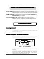
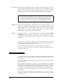
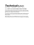
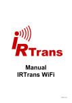
ADAPTIVE DELTA
MODULATION
PREPARATION............................................................................... 142
background .............................................................................. 142
TIMS adaptive delta modulator............................................... 142
the voltage controlled amplifier - VCA..................................................143
EXPERIMENT ................................................................................. 144
the adaptive control voltage ...................................................................144
VCA calibration ...................................................................... 144
manual control........................................................................................145
stability .............................................................................................145
adaptive control......................................................................................145
demodulation........................................................................... 146
TUTORIAL QUESTIONS ............................................................... 147
APPENDIX....................................................................................... 148
loop stability............................................................................ 148
Adaptive delta modulation
Vol D1, ch 15, rev 1.0
- 141
ADAPTIVE DELTA MODULATION
ACHIEVEMENTS: introduction to a variation of the basic delta modulator, which
adjusts the step size according to the slope of the signal being sampled
PREREQUISITES: completion of the experiments entitled Delta modulation and
Delta demodulation in this Volume.
ADVANCED MODULES: DELTA MODULATION UTILITIES; DELTA
DEMOD UTILITIES; WIDEBAND TRUE RMS METER optional.
PREPARATION
background
It is assumed that you have been introduced to the principles of adaptive delta
modulation in your course work.
TIMS adaptive delta modulator
The basic delta modulator was studied in the experiment entitled Delta modulation.
It is implemented by the arrangement shown in block diagram form in Figure 1.
+
message
in
LIMITER
-
SAMPLER
+V
delta
modulated
signal
output
INTEGRATOR
clock
k
Figure 1: basic delta modulator
You will remember that with this modulator there was a conflict when determining
the step size.
A large step size was required when sampling those parts of the input waveform of
steep slope. But a large step size worsened the granularity of the sampled signal
when the waveform being sampled was changing slowly. A small step size is
preferred in regions where the message has a small slope.
142 - D1
Adaptive delta modulation
This suggests the need for a controllable step size - the control being sensitive to the
slope of the sampled signal. This can be implemented by an arrangement such as is
illustrated in Figure 2.
message +
in
SAMPLER
LIMITER
+V
INTEGRATOR
delta
modulated
signal
output
clock
VCA
Figure 2: an adaptive delta modulator
The gain of the amplifier is adjusted in response to a control voltage from the
SAMPLER, which signals the onset of slope overload.
The step size is proportional to the amplifier gain. This was observed in an earlier
experiment.
Slope overload is indicated by a succession of output pulses of the same sign.
The TIMS SAMPLER monitors the delta modulated signal, and signals when there is
no change of polarity over 3 or more successive samples.
The actual ADAPTIVE CONTROL signal is +2 volt under ‘normal’ conditions, and rises
to +4 volt when slope overload is detected.
The gain of the amplifier, and hence the step size, is made proportional to this
control voltage. Provided the slope overload was only moderate the approximation
will ‘catch up’ with the wave being sampled. The gain will then return to normal
until the sampler again falls behind.
Much work has been done by researchers in this area, and sophisticated algorithms
have been developed which offer significant improvements over the simple system to
be examined in this experiment.
the voltage controlled amplifier - VCA
The VCA can be modelled with a MULTIPLIER. This is shown in Figure 3.
input
y(t)
k V y(t) output
V
k = multiplier constant
Figure 3: the voltage controlled amplifier
The control in Figure 3 is shown as a DC voltage. This may be set to any value in
the range ±Vmax. Beyond Vmax. the MULTIPLIER will overload. However, the
control voltage need not be DC, but can be time varying. Under these conditions the
arrangement is more likely be called a modulator.
Adaptive delta modulation
D1
- 143
You have met the MULTIPLIER constant, ‘k’, in earlier experiments of Part I,
where it was defined and measured.
EXPERIMENT
The block diagram of Figure 1 was modelled in the experiment entitled Delta
modulation. Refer to that experiment for details.
The adaptive delta modulator of Figure 2 differs only by the addition of a voltage
controlled amplifier (VCA), modelled, as described above, with a MULTIPLIER.
the adaptive control voltage
The DELTA MODULATION UTILITIES module has a socket labelled ADAPTIVE
OUTPUT. The signal from this socket is at a level of either +2 or +4 volts. The lower
output is what might be called the ‘normal’ level. If at any time the delta modulated
signal contains three or more consecutive samples of the same size then this signal
goes to the higher (+4) volt level 1. Three or more consecutive samples of the same
level indicates slope overload.
When including the VCA in the feedback path you must ensure that at no time will
either of the inputs to the MULTIPLIER exceed its safe (ie, linear) operating range
(say ±5 volts absolute maximum).
VCA calibration
Before setting up the delta modulator, it is wise to familiarise yourself with the
operation of the VCA.
T1 set up a VCA according to the block diagram of Figure 3. Use the VARIABLE
DC module as a control signal, and a sinewave as input. Connect
each via a BUFFER amplifier so that the values of Vmax/x and Vmax/y
can be determined. These are the overload levels for each of the
inputs. They are likely to be similar. Select DC coupling with the
front panel switch of the MULTIPLIER.
T2 measure the VCA gain for a control voltage of +2 volt. This is the ‘normal’
output from the ADAPTIVE CONTROL of the DELTA MODULATOR
UTILITIES module.
Your measurements should have shown that the MULTIPLIER can accept inputs
considerably in excess of the TIMS ANALOG REFERENCE LEVEL before
overload sets in.
1 more details in the TIMS Advanced Modules User Manual.
144 - D1
Adaptive delta modulation
Likewise, the INTEGRATOR input can, under some conditions, be subject to quite
large input signals; but it is robust and can also handle input amplitudes well in
excess of the TIMS ANALOG REFERENCE LEVEL.
You will notice that, except for the presence of the MULTIPLIER in the feedback
loop, the modulator is the same as that studied in the experiment entitled Delta
modulation. You should use the same setting up procedure as in that experiment,
with the adaptive control inhibited. This is done by connecting +2 volt in place of
the ADAPTIVE CONTROL voltage to the MULTIPLIER.
manual control
T3 model the block diagram of Figure 1. This is not the adaptive modulator.
Refer to the experiment entitled Delta modulation for details. The
amplifier in the feedback loop is modelled with two BUFFER
amplifiers in cascade.
T4 observe the two inputs to the SUMMER. Adjust the feedback gain so that the
sawtooth shows some evidence of (ie, moderate) slope overload.
T5 observe the control voltage from the ADAPTIVE CONTROL output socket. It will
be alternating between V1 (no slope overload) and V2 volt (following
the onset of, and coincident with, the slope overload). Record the
value of V1 (about 2 volt).
T6 insert the VCA between the SAMPLER and the BUFFER AMPLIFIER. Set the
control voltage to the VCA to V1 volts, obtained from the VARIABLE
DC supply.
T7 observe the two inputs to the SUMMER. These should be exactly the same as
observed during Task T4. The slope overload should, therefor, be
apparent as before.
stability
There are now three amplifiers in the feedback loop. At the best of times this could
be a cause for concern - the stability of the whole system could be compromised.
Refer to the Appendix to this experiment for further comment.
adaptive control
The VCA is now set up in the feedback loop, but is currently in a passive mode.
You are now ready to implement adaptive control of the loop gain by replacing the
fixed control voltage V1 with the adaptive control voltage from the modulator.
What you will want to observe is the reduction of the length of the period of the
slope overload.
T8 while watching the length of the slope overload portion of the sawtooth
waveform from the INTEGRATOR, replace the DC voltage from the
VARIABLE DC supply to the VCA with the ADAPTIVE CONTROL
voltage from the modulator.
Adaptive delta modulation
D1
- 145
T9 replace the DC control voltage with the ADAPTIVE CONTROL from the SAMPLER.
Notice that the slope overload remains as for the conditions of the
previous Task when the control voltage was +4 volt, but that the
granularity at the extrema of the message has not been worsened.
To change between adaptive and non-adaptive operation move
the patch cord from the ADAPTIVE CONTROL output socket of the
SAMPLER to the preset (V1) output of the VARIABLE DC module.
T10 spend some time examining the waveforms at the various interfaces. As
necessary, replace the ADAPTIVE CONTROL voltage with the manual
(DC voltage) control. Don`t forget to monitor the ADAPTIVE CONTROL
voltage itself. In other words, make sure you make enough
observations to appreciate what is happening.
T11 use a ‘complex message’, as described in the experiment entitled Delta
modulation, and compare results (by visual inspection of the
INTEGRATOR output waveform) with and without the adaptive feedback
operating.
You should now be reasonably confident, from your observations at the modulator
(transmitter), that the adaptive feedback control will improve the performance of the
system as observed at the demodulator (receiver).
Thus it might be agreed that the object of the experiment has been achieved.
For positive verification, however, it is necessary to build a demodulator and make
some further observations.
demodulation
It is essential that you have already completed the experiment entitled Delta
demodulation. This introduced methods of noise and distortion measurement, which
are required now.
You should now model a delta demodulator, as described in the experiment entitled
Delta demodulation..
Whilst absolute measurement of signal to noise-plus-distortion ratio (SNDR)
measurements are of interest, of greater interest in the present situation is to observe
the change to the demodulated waveform which happens when the adaptive feedback
is introduced. This is a qualitative measurement but nonetheless very instructive.
The setting up procedure at the demodulator will be somewhat similar to that used at
the modulator.
Of interest will be a measurement to resolve the question: is it necessary to make the
demodulator adaptive in the same manner as at the modulator ? Is there a penalty
for not doing so ?
146 - D1
Adaptive delta modulation
T12 set up a demodulator. Use a complex message.
waveforms under various conditions.
Observe recovered
TUTORIAL QUESTIONS
Q1 make a positive statement about how your observations at the modulator
confirmed that the ADAPTIVE CONTROL ‘improved’ the performance of
the modulator.
Adaptive delta modulation
D1
- 147
APPENDIX
loop stability
You are working with a feedback loop. At the best of times these can run into
instability if the loop gain is too high. Some of this instability can be caused by unplanned for phase changes round the loop.
SAMPLER output
to SUMMER
ADAPTIVE CONTROL
voltage
DC for mean
gain control
Figure 4: gain modification using VCA
The presence of two BUFFER
amplifiers in cascade does not
help the situation. These were
placed there in the non-adaptive
modulator as a convenient
method of changing the loop
gain.
Now there is an extra source of
phase change introduced by the VCA, and also a new source of gain adjustment. If it
turns out that the gain provided by the two BUFFER amplifiers is near unity it might
be prudent to remove them.
Small gain adjustment could be introduced by the scheme illustrated in Figure 4.
This scheme has not been included in any of the Tasks. If you elect to use it, then
modify the instructions accordingly.
148 - D1
Adaptive delta modulation