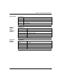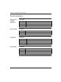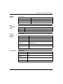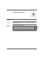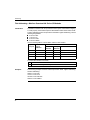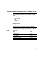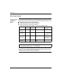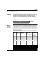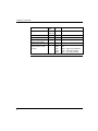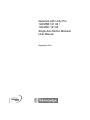
1
Quantum with Unity Pro
140 MSB 101 00 /
140 MSC 101 00
Single Axis Motion Modules
User Manual
33002495 01
September 2004
2
Table of Contents
Safety Information . . . . . . . . . . . . . . . . . . . . . . . . . . . . . . . . . . . . 5
About the Book . . . . . . . . . . . . . . . . . . . . . . . . . . . . . . . . . . . . . . . 7
Part I Functional Overview . . . . . . . . . . . . . . . . . . . . . . . . . . . . . 9
At a Glance . . . . . . . . . . . . . . . . . . . . . . . . . . . . . . . . . . . . . . . . . . . . . . . . . . . . . . 9
Chapter 1
Overview . . . . . . . . . . . . . . . . . . . . . . . . . . . . . . . . . . . . . . . . . . . 11
Overview . . . . . . . . . . . . . . . . . . . . . . . . . . . . . . . . . . . . . . . . . . . . . . . . . . . . . . . 11
Chapter 2
Specifications and Hardware Overview . . . . . . . . . . . . . . . . . . 13
140 MSB 101 00 and 140 MSC 101 00 Modules . . . . . . . . . . . . . . . . . . . . . . . . 13
Chapter 3
System Information . . . . . . . . . . . . . . . . . . . . . . . . . . . . . . . . . . 17
At a Glance . . . . . . . . . . . . . . . . . . . . . . . . . . . . . . . . . . . . . . . . . . . . . . . . . . . . .
Flash Memory . . . . . . . . . . . . . . . . . . . . . . . . . . . . . . . . . . . . . . . . . . . . . . . . . . .
Communications Protocol . . . . . . . . . . . . . . . . . . . . . . . . . . . . . . . . . . . . . . . . . .
On-line and Off-line Development with MMDS . . . . . . . . . . . . . . . . . . . . . . . . . .
17
18
19
20
Part II Module Description . . . . . . . . . . . . . . . . . . . . . . . . . . . . . 21
At a Glance . . . . . . . . . . . . . . . . . . . . . . . . . . . . . . . . . . . . . . . . . . . . . . . . . . . . . 21
Chapter 4
140 MSx 101 00: Single Axis Motion Module . . . . . . . . . . . . . . 23
Overview . . . . . . . . . . . . . . . . . . . . . . . . . . . . . . . . . . . . . . . . . . . . . . . . . . . . . . .
Quantum Single Axis Motion (MSx) Modules . . . . . . . . . . . . . . . . . . . . . . . . . . .
Front Panel Indicators for the 140 MSx 101 00. . . . . . . . . . . . . . . . . . . . . . . . . .
Front Panel Connectors . . . . . . . . . . . . . . . . . . . . . . . . . . . . . . . . . . . . . . . . . . .
Rear Panel Switches . . . . . . . . . . . . . . . . . . . . . . . . . . . . . . . . . . . . . . . . . . . . . .
Operational Specifications. . . . . . . . . . . . . . . . . . . . . . . . . . . . . . . . . . . . . . . . . .
Electrical Specifications. . . . . . . . . . . . . . . . . . . . . . . . . . . . . . . . . . . . . . . . . . . .
Parts List . . . . . . . . . . . . . . . . . . . . . . . . . . . . . . . . . . . . . . . . . . . . . . . . . . . . . . .
23
24
25
27
30
31
34
37
3
Chapter 5
Connection accessories . . . . . . . . . . . . . . . . . . . . . . . . . . . . . . 39
Overview . . . . . . . . . . . . . . . . . . . . . . . . . . . . . . . . . . . . . . . . . . . . . . . . . . . . . . . 39
The Breakout Module 690 MCB 000 00 . . . . . . . . . . . . . . . . . . . . . . . . . . . . . . . 40
Breakout Module Cover 690 MCB 101 00 . . . . . . . . . . . . . . . . . . . . . . . . . . . . . . 43
Part III Configuration . . . . . . . . . . . . . . . . . . . . . . . . . . . . . . . . . . . 45
At a Glance . . . . . . . . . . . . . . . . . . . . . . . . . . . . . . . . . . . . . . . . . . . . . . . . . . . . . 45
Chapter 6
Quantum Addressing Modes . . . . . . . . . . . . . . . . . . . . . . . . . . 47
Overview . . . . . . . . . . . . . . . . . . . . . . . . . . . . . . . . . . . . . . . . . . . . . . . . . . . . . . . 47
Flat Addressing—Modicon Quantum 800 Series I/O Modules . . . . . . . . . . . . . . 48
Topological Addressing—Modicon Quantum 800 Series I/O
Modules with Unity. . . . . . . . . . . . . . . . . . . . . . . . . . . . . . . . . . . . . . . . . . . . . . . . 49
Addressing Example . . . . . . . . . . . . . . . . . . . . . . . . . . . . . . . . . . . . . . . . . . . . . . 50
Discrete I/O Bit Numbering . . . . . . . . . . . . . . . . . . . . . . . . . . . . . . . . . . . . . . . . . 51
Addressing . . . . . . . . . . . . . . . . . . . . . . . . . . . . . . . . . . . . . . . . . . . . . . . . . . . . . . 52
Chapter 7
IO Mapping Configuration . . . . . . . . . . . . . . . . . . . . . . . . . . . . . 53
Parameter Configuration . . . . . . . . . . . . . . . . . . . . . . . . . . . . . . . . . . . . . . . . . . . 53
Chapter 8
Hardware Installation. . . . . . . . . . . . . . . . . . . . . . . . . . . . . . . . . 55
At a Glance . . . . . . . . . . . . . . . . . . . . . . . . . . . . . . . . . . . . . . . . . . . . . . . . . . . . . 55
Mounting and Connecting the MSx Modules . . . . . . . . . . . . . . . . . . . . . . . . . . . . 56
Conforming to European CE Approval Standards . . . . . . . . . . . . . . . . . . . . . . . . 61
Chapter 9
Setting the Rear Panel Switches . . . . . . . . . . . . . . . . . . . . . . . 63
Overview . . . . . . . . . . . . . . . . . . . . . . . . . . . . . . . . . . . . . . . . . . . . . . . . . . . . . . . 63
Setting the Operating Mode with SW1. . . . . . . . . . . . . . . . . . . . . . . . . . . . . . . . . 64
Setting Modbus Comm Characteristics with SW2 . . . . . . . . . . . . . . . . . . . . . . . . 65
Index
4
. . . . . . . . . . . . . . . . . . . . . . . . . . . . . . . . . . . . . . . . . . . . . . . 67
Safety Information
§
Important Information
NOTICE
Read these instructions carefully, and look at the equipment to become familiar with
the device before trying to install, operate, or maintain it. The following special
messages may appear throughout this documentation or on the equipment to warn
of potential hazards or to call attention to information that clarifies or simplifies a
procedure.
The addition of this symbol to a Danger or Warning safety label indicates
that an electrical hazard exists, which will result in personal injury if the
instructions are not followed.
This is the safety alert symbol. It is used to alert you to potential personal
injury hazards. Obey all safety messages that follow this symbol to avoid
possible injury or death.
DANGER
DANGER indicates an imminently hazardous situation, which, if not avoided, will
result in death, serious injury, or equipment damage.
WARNING
WARNING indicates a potentially hazardous situation, which, if not avoided, can result
in death, serious injury, or equipment damage.
CAUTION
CAUTION indicates a potentially hazardous situation, which, if not avoided, can result
in injury or equipment damage.
5
Safety Information
PLEASE NOTE
6
Electrical equipment should be serviced only by qualified personnel. No
responsibility is assumed by Schneider Electric for any consequences arising out of
the use of this material. This document is not intended as an instruction manual for
untrained persons.
© 2004 Schneider Electric. All Rights Reserved.
About the Book
At a Glance
Document Scope
This documentation describes the functionality of the Quantum Automation Series
single axis motion (MSx) modules (140 MSB 101 00 and 140 MSC 101 00).
This documentation is valid for Unity Pro from version 2.0.
Validity Note
The data and illustrations found in this documentation are not binding. We reserve
the right to modify our products in line with our policy of continuous product
development. The information in this document is subject to change without notice
and should not be construed as a commitment by Schneider Electric.
7
About the Book
Related
Documents
Title of Documentation
Reference Number
Quantum Hardware Reference Manual
UNYUSE10010V20E
Quantum Discrete and Analog I/O Reference Manual
UNYUSE10010V20E
Quantum Experts and Communication Reference Manual
UNYUSE10010V20E
Grounding and Electromagnetic Compatibility of PLC Systems User
Manual
UNYUSE10010V20E
Quantum and Premium Communication Architecture Reference
Manual
UNYUSE10410V20E
Single Axis Software System (SASS) Motion User Guide
Modicon Motion Development Software (MMDS) User Guide
Lexium 17D Series Servo Drive User Guide
890USE12000
Note: The above mentioned documentations are only available in online form at
this time.
Product Related
Warnings
Schneider Electric assumes no responsibility for any errors that may appear in this
document. If you have any suggestions for improvements or amendments or have
found errors in this publication, please notify us.
No part of this document may be reproduced in any form or by any means, electronic
or mechanical, including photocopying, without express written permission of
Schneider Electric.
All pertinent state, regional, and local safety regulations must be observed when
installing and using this product. For reasons of safety and to ensure compliance
with documented system data, only the manufacturer should perform repairs to
components.
When controllers are used for applications with technical safety requirements,
please follow the relevant instructions.
Failure to use Schneider Electric software or approved software with our hardware
products may result in injury, harm, or improper operating results.
Failure to observe this product related warning can result in injury or equipment
damage.
User Comments
We welcome your comments about this document. You can reach us by e-mail at
[email protected]
8
Functional Overview
I
At a Glance
Introduction
This part describes the functional overview of the single axis motion modules
(140 MSB 101 00 and 140 MSC 101 00).
What's in
this Part?
This part contains the following chapters:
Chapter Chapter Name
Page
1
Overview
11
2
Specifications and Hardware Overview
13
3
System Information
17
9
Functional Overview
10
Overview
1
Overview
Single Axis
Motion Modules
The Quantum Automation Series single axis motion (MSx) modules (140 MSB 101
00 and 140 MSC 101 00) are designed to control a single axis of motion using
advanced digital brushless motion control. This capability provides optimal control
by eliminating potentiometer adjustments and analog velocity loops. The MSx
modules are designed to interface directly to the Schneider Electric Lexium 17D
series brushless servo amplifiers as well as other types of dc and brushless drives.
Note: These modules are designed to serve your many and varied applications
with great accuracy and speed. However, certain applications might be outside the
scope of this module. Please consult Schneider Electric for applications
information if you intend to use the module specifically for precise velocity control.
The primary feedback used by the direct numeric processing (DNP) servo system is
position information from either a resolver or an encoder mounted to the motor.
Velocity information is derived from the position information, rather than being
received from a velocity transducer. This leads to some inaccuracies when using the
DNP servo as a velocity controller. Small speed irregularities may result, particularly
at slower speeds.
System
Configuration
The Quantum single axis motion (MSx) modules are incremental encoder (140 MSB
101 00) or resolver and encoder (140 MSC 101 00) feedback-only modules
contained in a single-width housing. It works with servo motors that use Lexium
drives and other types of DC and brushless drives from other manufacturers.
11
Overview
12
Specifications and
Hardware Overview
2
140 MSB 101 00 and 140 MSC 101 00 Modules
MSx Modules
The Quantum single axis motion (MSx) modules are incremental encoder
(140 MSB 101 00) or resolver and encoder (140 MSC 101 00) feedback-only
modules contained in a single-width housing. It works with servo motors that use
Cyberline drives and other types of DC and brushless drives from other
manufacturers.
13
Specifications and Hardware Overview
The illustration below shows a typical configuration of a single axis motion control
system
MMDS on PC
or compatible
Quantum
CPU
Modbus (for programming)
Quantum Backplane
MSx Module
Breakout Module
Analog I/O
Additional
Discrete
I/O
Drive
Motor
Feedback
Limits
Motor
Load
The modules contain I/O to interface to the drive and the machine, including drive
enable, drive fault, and a variety of user-configurable signals. The modules also
include a high speed input pin to perform high speed position capture
14
Specifications and Hardware Overview
See the illustration of a Quantum MSx module below.
Model Number
Module Description
Color Code
LED Area
Removable Door
Customer Identification Label
(Fold label and place it inside door)
Modbus
Connector
Servo Port
Connectors
Note: MSx modules are only installed in Quantum backplanes. Refer to the
Quantum Automation Series Hardware Reference Guide for detailed specifications
of all Quantum modules and associated hardware. (Reference No. see Related
Documents, p. 8).
15
Specifications and Hardware Overview
16
System Information
3
At a Glance
Purpose
This Chapter provides system information on Flash Memory, Communications
Protocol, and On-line and Off-line Development with MMDS.
Note: Refer to Appendix E in the Single Axis Software System (SASS) Motion User
Guide for system checkout information.
What's in this
Chapter?
This chapter contains the following topics:
Topic
Page
Flash Memory
18
Communications Protocol
19
On-line and Off-line Development with MMDS
20
17
System Information
Flash Memory
Flash EEPROM
18
The MSx comes with a flash EEPROM that allows storage of application programs
and configuration parameters such as servo parameters, speed limits, etc. The flash
also accepts firmware updates as firmware enhancements become available.
System Information
Communications Protocol
Backplane
Communications
Backplane communications with the MSx is through six 3x and 4x registers, which
must be I/O mapped to the MSx. Modbus communication with the MSx is through
six pairs of registers via the Modbus communication link. The register format is very
rigid. The first register sent to the module (4X)is always the control register, and the
second is always the command register. The first register returned from the module
(3X) is always the current status of the module, while the second register returned
is always an echo of the command register. All remaining registers, data register 1
... 4, are reserved for data and are used as necessary. For additional information
refer to Single Axis Software System (SASS) Motion User Guide.
19
System Information
On-line and Off-line Development with MMDS
MMDS
The Modicon Motion Development Software (MMDS), Version 4.1 or higher, is an
on-line/off-line software package which runs on a user-supplied IBM PC or
compatible computer. MMDS is purchased separately. The computer with MMDS
can be connected to the MSx through an RS-232 serial interface.
With MMDS, you can set parameters, check module diagnostics, and exercise the
motor during initial system setup. You can also write motion programs and download
them into the MSx directly.
Note: If the module is I/O mapped in a Quantum PLC and the user has a Modbus
Plus adaptor card in their PC, it is possible to do on˜line development over the
Modbus Plus network. Refer to the Modicon Motion Development Software
(MMDS) User Guide for details.
20
Module Description
II
At a Glance
Introduction
The following part provides information on the Quantum Automation Series Single
Motion (MSx) Modules, related Hardware and Specifications.
What's in this
Part?
This part contains the following chapters:
Chapter Chapter Name
Page
4
140 MSx 101 00: Single Axis Motion Module
23
5
Connection accessories
39
21
Module Description
22
140 MSx 101 00: Single
Axis Motion Module
4
Overview
Purpose
The following chapter provides information of the Quantum 140 MSx 101 00 module.
What's in this
Chapter?
This chapter contains the following topics:
Topic
Page
Quantum Single Axis Motion (MSx) Modules
24
Front Panel Indicators for the 140 MSx 101 00
25
Front Panel Connectors
27
Rear Panel Switches
30
Operational Specifications
31
Electrical Specifications
34
Parts List
37
23
140 MSx 101 00: Single Axis Motion Module
Quantum Single Axis Motion (MSx) Modules
Function
The Quantum single axis motion (MSx) modules are incremental encoder
(140 MSB 101 00) or resolver and encoder (140 MSC 101 00) feedback-only
modules contained in a single-width housing. It works with servo motors that use
Lexium drives and other types of DC and brushless drives from other manufacturers.
Illustration
The following figure shows the 140 MSx 101 00 module and its components.
Model Number
Module Description
Color Code
LED Area
Removable Door
Modbus
Connector
Servo Port
Connectors
24
Customer Identification Label
(Fold label and place it inside door)
140 MSx 101 00: Single Axis Motion Module
Front Panel Indicators for the 140 MSx 101 00
LED Indicators
Panel
The following illustration represents the LED Indicators Panel.
Active
Ready
+Lim ok
-Lim ok
Home
In 4
In 5
In 6
In 7
Drv Flt
Drv En
Out 1
Out 2
Out 3
Modbus
Moving
In Pos
25
140 MSx 101 00: Single Axis Motion Module
LED Indicators
and Descriptions
26
There are seventeen LED indicators visible on the front panel:
LEDs
Color
Indication when On
Active
Green
Bus communication is present.
Ready
Green
The module has passed powerup diagnostics
+Lim ok
Green
Digital Input 1 active
-Lim ok
Green
Digital Input 2 active
Home
Green
Digital Input 3 active
In 4
Green
Digital Input 4 active
In 5
Green
Digital Input 5 active
In 6
Green
Digital Input 6 active
In 7
Green
Digital Input 7 active
Drv Flt
Red
Fault signal from drive
Drv En
Green
Drive enabled
Out 1
Green
Digital Output 1 active
Out 2
Green
Digital Output 2 active
Out 3
Green
Digital Output 3 active
Modbus
Green
Communications are active on the Modbus port
Moving
Amber Motor is moving
In Pos
Amber Motion is within the in position of the final target
140 MSx 101 00: Single Axis Motion Module
Front Panel Connectors
General
There are two connectors located on the front of the Module.
z A SUB-D 9 connector for RS232 Modbus link
z A SUB-D 50 port for connection to the servo drive.
Modbus
Connector
The following table shows the Modbus port pinout connectors.
PIN
Signal Function
1
Servo Connector
Shield
2
TXD
Serial data
3
RXD
Serial data
4
GND
Ground
5
DTR
Control Line
6
DSR
Control Line
7
RTS
Control Line
8
CTS
Control Line
The following table shows the Servo Connector Signals 34 trough 50.
PIN
Signals 140 MSB 101 00
Signals 140 MSC 101 00
34
Velocity+
Phase A
35
N/C
Phase B
36
N/C
Phase C
37
Velocity-/Phase common
Velocity-/Phase common
38
Drive fault
Drive fault
39
Drive enable contact (NO)
Drive enable contact (NO)
40
Drive enable contact N/C
Drive enable contact N/C
41
Drive enable common
Drive enable common
42
Overtemp high
Overtemp high
43
Overtemp low
Overtemp low
44
Cosine input high
Cosine input high
45
Cosine input low
Cosine input low
46
Sine input high
Sine input high
47
N/C
Sine input low
48
N/C
Reference output high
49
N/C
Reference output low
50
N/C
N/C
27
140 MSx 101 00: Single Axis Motion Module
The following table shows the Servo Connector Signals 18 trough 33.
PIN
28
Signals 140 MSB 101 00
Signals 140 MSC 101 00
18
24 VDC
24 VDC
19
24 V common
24 V common
20
Brake output (Auxiliary output 1)
Brake output (Auxiliary output 1)
21
Auxiliary output 2
Auxiliary output 2
22
Auxiliary output 3
Auxiliary output 3
23
Limit CW (Auxiliary input 1)
Limit CW (Auxiliary input 1)
24
Limit CCW (Auxiliary input 2)
Limit CCW (Auxiliary input 2)
25
Home (Auxiliary input 3)
Home (Auxiliary input 3)
26
Auxiliary input 4
Auxiliary input 4
27
Auxiliary input 5
Auxiliary input 5
28
Auxiliary input 6
Auxiliary input 6
29
Auxiliary input 7
Auxiliary input 7
30
High speed input
High speed input
31
Analog output
Analog output
32
Analog common
Analog common
33
Analog input
Analog input
140 MSx 101 00: Single Axis Motion Module
The following table shows the Servo Connector Signals 1 trough 17.
PIN
Signals 140 MSB 101 00
Signals 140 MSC 101 00
1
Encoder 1 Phase A+
Encoder 1 Phase A+
2
Encoder 1 Phase A-
Encoder 1 Phase A-
3
Encoder 1 Phase B+
Encoder 1 Phase B+
4
Encoder 1 Phase B-
Encoder 1 Phase B-
5
Encoder 1 Mark+
Encoder 1 Mark+
6
Encoder 1 Mark-
Encoder 1 Mark-
7
Encoder 2 Phase A+
Encoder 2 Phase A+
8
Encoder 2 Phase A-
Encoder 2 Phase A-
9
Encoder 2 Phase B+
Encoder 2 Phase B+
10
Encoder 2 Phase B-
Encoder 2 Phase B-
11
Encoder 2 Mark+
Encoder 2 Mark+
12
Encoder 2 Mark-
Encoder 2 Mark-
13
N/C
N/C
14
N/C
N/C
15
N/C
N/C
16
N/C
N/C
17
N/C (Not connected)
N/C (Not connected)
29
140 MSx 101 00: Single Axis Motion Module
Rear Panel Switches
Introduction
The MSx has an RS-232 serial port to connect the module to an IBM PC (or
compatible) running the Modicon Motion Development Software (MMDS). A twoposition DIP switch is located on the rear panel of the module (below).
z SW1 is used to specify the module’s operating mode (984 or MMDS control).
z SW2 is used to specify the communication characteristics of the Modbus port
upon power-up.
Note: SW1 and SW2 are open when they are switched away from the internal PCB
of the module.
Illustration
The following figure shows the two-position DIP switch.
CLOSED
OPEN
SLIDE SWITCH
AREA OF DETAIL
Description
The following table shows the settings and functions for DIP Switches.
Switch Setting
SW1
SW2
*Closed
MMDS control
Open
PLC control
Closed
Programmed baud
*Open
Modbus default
*Factory setting
30
Function
140 MSx 101 00: Single Axis Motion Module
Operational Specifications
Servo
Communication
Application
Program
Specifications
Commutation Update Row
0.25 ms
Velocity Loop Update Rate
0.5 ms
Velocity Loop Bandwidth
> 100 Hz
Velocity Range
0 – 6000 rpm
Position Loop Update rate
1 ms
Position Accuracy – Resolver
10 arc minutes typical, 15 arc minutes max
Position Repeatability – Resolver
5 arc minutes max
Position Accuracy – Encoder
Encoder dependent, 0.5 arc minutes max
Specifications
Protocol
Modbus
Address (set by software)
1 default
Baud Rate (set by software)
300 – 19200 baud, 9600 default
Specifications
Execution Rate
See note below
Storage
650 instructions
Note: A majority of the instructions typically take 1 ms to execute. The execution
time of an instruction, though, is not constant. The execution time can increase due
to factors such as: if the Sync Ratio Mode is on, how often the position generator
must execute to plan out new moves, how many whenevers are enabled, the
number of sources requesting commands be executed (e.g., backplane, internal
program, Modbus port), etc. If timing is extremely critical to an application, actual
time must be determined experimentally by running the actual application program.
31
140 MSx 101 00: Single Axis Motion Module
High Speed Input
Specifications
Position Capture Time
250 ms max
Isolation
500 V to system bus
Pulse Width
25 ms
Minimum Time Between Successive Captures 20 ms
Discrete Inputs
Specifications
Number
Discrete Outputs
7
Scan Time
1.5 ms
Isolation
500 V to system bus
Specifications
Number
3
Update Time 10 ms max
Analog Input
32
Isolation
500 V to system bus
Reset State
0 V, nominal
On State
24 V, nominal
Output Type
Totem pole (sink/source)
Protection
Short circuit, overvoltage
Fault
Overcurrent detected
Specifications
Number
1
Scan Time
15 ms
Data
User configurable
Range
10 V
Accuracy
100mV, plus offset
140 MSx 101 00: Single Axis Motion Module
Analog Output
Resolver
feedback
(Fully
Configured
Version)
Incremental
Encoder
Feedback
Specifications
Number
1
Scan Time
20 ms
Data
User Configurable
Range
10V
Accuracy
50 mV, plus offset
Specifications
Conversion Method
Tracking
Resolver Style
Transmit
Excitation Frequency
5 kHz
Excitation Amplitude
Automatically adjusted
Excitation Current
120 mA
Loss of Feedback
Detected within 40 ms
Specifications
Resolution
4 times line count
Signals
A, B, Mark
Signal Frequency
200 kHz, up to 500 kHz with reduced noise immunity
Encoder Output style
Differential, 5 V
Loss of Feedback
Detected within 40 ms
33
140 MSx 101 00: Single Axis Motion Module
Electrical Specifications
Discrete Inputs
and HIgh
Speed Input
Discrete Output
Analog Input
Analog Output
34
Specifications
Input Impedance
3.5 kΩ
Inputs On
15 Vdc min
Inputs Off
5 Vdc max
Isolation
500 Vac to system bus
Specifications
Drive Capability
150 mA at user supplied 19.2 ... 30 Vdc resistive
Protection
Current limit, thermal
Isolation
500 Vac to system bus
Specifications
Resolution
10 bits
Input Impedance
30 kΩ
Offset
50 mV
Accuracy
100 mV, plus offset
Specifications
Resolution
12 bits
Drive Capability
3 mA
Offset
50 mV
Accuracy
50 mV, plus offset
140 MSx 101 00: Single Axis Motion Module
Resolver
Interface
Motor
Temperature
Input
Encoder
Feedback
Interface
Drive Interface
Specifications
Reference
5 0.05 kHz 1.6 ... 5.5 v rms 50 mA drive capability
Sine/Cosine Input Impedance
3 kΩ
Resolution
16 bits to 300 rpm 14 bits to 1350 rpm 12 bits to 6000 rpm
Accuracy
10 arc minutes, typical, resolver dependent
Specifications
Normal State
Short circuit, 2 mA sink max
Fault State
Open circuit
Isolation
500 Vac to system bus
Specifications
Input Range
-0.7 ... 7Vdc
Input Impedance
145Ω, nominal
Differential Signals, HIgh
+2 V differential, min
Differential Signals, Low
-2 V differential, min
Maximum Encoder
Frequency
200 kHz square wave (55% ... 45% with less than 15° of
quadrature error)
Isolation
500 Vac to system bus with external power supply
Minimum Encoder Pulse
Width
1 ms
Specifications
Drive Fault Input
True high, TTL compatible relative to 10K internal pull-up resistor
Drive Enable Relay
Form C contacts 120 [email protected] resistive 30 [email protected] resistive
Current Command
Voltages
10 Vdc
Current Command
Summing Accuracy
0 0.1 Vdc
Current Commands
3 mA drive capability
35
140 MSx 101 00: Single Axis Motion Module
Power
Requirements
Specifications
Main Power Input 5 V 5% @750 mA (with no encoders or resolvers attached, output off)
Main Power Input 5 V 5% @1000 mA (with maximum encoder and resolver load, outputs
on)
Hot Swap Surge
Current
36
Less than 5 A
140 MSx 101 00: Single Axis Motion Module
Parts List
Parts List
Parts List
Part Number
Description
140 MSB 101 00
Quantum Motion Module
140 MSC 101 00
Quantum Motion Module
690 MCB 000 00
Breakout Module, 50 Signal
690 MCB 101 00
CE Compliant Breakout Module Cover
690 MCI 000 01
Low profile DB50/DB50 cable, 1 ft
690 MCI 000 03
Low profile DB50/DB50 cable, 3 ft
690 MCI 000 06
Low profile DB50/DB50 cable, 6 ft
37
140 MSx 101 00: Single Axis Motion Module
38
Connection accessories
5
Overview
Purpose
The following chapter provides information of the connection accessories for the
140 MSx 101 00 module.
What's in this
Chapter?
This chapter contains the following topics:
Topic
Page
The Breakout Module 690 MCB 000 00
40
Breakout Module Cover 690 MCB 101 00
43
39
Connection accessories
The Breakout Module 690 MCB 000 00
Breakout Module
The Breakout Module (see below) is the I/O wiring block connector for the
140 MSx 101 00 Single Axis Motion Module servo connections. It is connected to
the MSx via a Breakout Module cable (690 MCI 000 xx) at the 50-pin servo
connector.
Illustration
The following figure shows the Breakout Module, with its Earth ground and Servo
Port Connectors.
Breakout Module
Servo Port
Connector
(to the MSx)
Servo Connector
Feedback Signals
(three rows, 1-50)
Earth ground for
termination of shields
Reference
Labels
40
Provided with the Breakout Module are labels for the MSB and MSC modules.
These labels are a reference for the Breakout Module signal names. Attach the
applicable label near this Breakout Module in your cabinet or rack.
Connection accessories
Reference Label
for the MSB
The following figure represents the reference label for the MSB Breakout Module
connection names.
Modicon 140 MSB
1
2
3
4
CH2 A+
5
101 00 Connections
18 24 VDC
19 24 Com
20 Brake
34 VEL+
35 N/C
36 N/C
CH2 M+
21 OUT 2
22 OUT 3
37 VEL38 Drv Fit
6
CH2 M-
23 CW Lim
39 EN NO
7
8
CH3 A+
CH3 A-
24 CCW Lim
25 Home
40 EN NC
41 EN Com
9
CH3 B+
10
11
CH3 BCH3 M+
26 IN 4
27 IN 5
28 IN 6
12
CH3 M13 N/C
29 IN 7
30 HSI
42 OTemp+
43 OTemp44 N/C
45 N/C
14
31
47 N/C
15 N/C
32 AN Com
48
16
33
49 N/C
CH2 ACH2 B+
CH2 B-
46
17 N/C
41
Connection accessories
Reference Label
for the MSC
The following figure represents the reference label for the MSC Breakout Module
connection names.
Modicon 140 MSC
18 24 VDC
19 24 Com
20 Brake
34 ∅A
35 ∅B
36 ∅C
CH2 M+
21 OUT 2
22 OUT 3
37 ∅COM
38 Drv Fit
6
CH2 M-
23 CW Lim
7
8
CH3 A+
CH3 A-
24 CCW Lim
25 Home
39 EN NO
40 EN NC
41 EN Com
26 IN 4
27 IN 5
28 IN 6
1
2
3
4
CH2 A+
5
CH2 ACH2 B+
CH2 B-
9
CH3 B+
10
11
CH3 BCH3 M+
12
CH3 M-
13 N/C
14 N/C
42
29 IN 7
30 HSI
15 N/C
31 AN OUT
32 AN Com
16 N/C
33 AN IN
17 N/C
Wiring
Information
101 00 Connections
42 OTemp+
43 OTemp44 COS+
45 COS46 SIN+
47 SIN48 REF+
49 REF50 N/C
Refer to the Lexium 17D User's Guide, Appendix C, Drive-to-Controller Wiring
Diagrams to obtain cabling informations.
Connection accessories
Breakout Module Cover 690 MCB 101 00
Breakout Module
Cover
A Breakout Module cover (below), Modicon # 690 MCB 101 00, is also available,
which shields the termination points of the breakout module from electrostatic
discharge. It is a metal plate that is screwed down to the same panel as the DIN rail
that holds the Breakout Module. This cover is required to make the system CE*
compliant (refer to Mounting and Connecting the MSx Modules, p. 56 for installation
instructions).
The Breakout Module cover protects against electrostatic discharge.
* The CE mark indicates compliance with the European Directive on
Electromagnetic Compatibility (EMC) (89/336/EEC). In order to maintain
compliance, the Quantum system must be installed per the installation instructions.
43
Connection accessories
44
Configuration
III
At a Glance
Introduction
The following part provides information about the configuration of the
140 MSx 101 00 module.
What's in this
Part?
This part contains the following chapters:
Chapter Chapter Name
Page
6
Quantum Addressing Modes
47
7
IO Mapping Configuration
53
8
Hardware Installation
55
9
Setting the Rear Panel Switches
63
45
Configuration
46
Quantum Addressing Modes
6
Overview
Purpose
In the functional description of this Expert Module the register addressing (3x, 4x)
established in the Quantum world is widely used. To allow the user an easy
transition to the addressing modes provided by Unity Pro, this chapter describes the
different modes Unity Pro allows to address the data from a Quantum module:
z Flat Addressing
z Topological Addressing
What's in this
Chapter?
This chapter contains the following topics:
Topic
Page
Flat Addressing—Modicon Quantum 800 Series I/O Modules
48
Topological Addressing—Modicon Quantum 800 Series I/O Modules with Unity
49
Addressing Example
50
Discrete I/O Bit Numbering
51
Addressing
52
47
Addressing
Flat Addressing—Modicon Quantum 800 Series I/O Modules
Introduction
The Modicon Quantum with Unity modules follow a system of flat address mapping.
To work properly. each module requires a determinate number of bits and/or words.
The IEC addressing system is equivalent to the 984LL register addressing. Use the
following assignments:
z 0x is now %Mx
z 1x is now %Ix
z 3x is now %IWx
z 4x is now %MWx
Use the following table to convert 984LL notation to IEC notation.
Outputs
and Inputs
984LL Notation IEC Notation
Register
System Bits
Addresses
and Words
Memory
Addresses
I/O Addresses
output
0x
System Bit
%Mx
%Qx
input
1x
System Bit
%Ix
%Ix
input
3x
System Word
%IWx
%IWx
output
4x
System Word
%MWx
%QWx
To access the I/O data of a module,
Step Action
1
Examples
48
Enter the address range in the configuration screen.
The following examples show the relationship between 984LL register addressing
and IEC addressing:
000001 is now %M1
100101 is now %I101
301024 is now %IW1024
400010 is now %MW10
Addressing
Topological Addressing—Modicon Quantum 800 Series I/O Modules with Unity
Introduction
Use topological addressing to access I/O data items. Identify the topological location
of the module within a Modicon Quantum with Unity system using the following
notation:
%<Exchangetype><Objecttype>[\b.e\]r.m.c[.rank]
Abbreviations used:
z b = bus
z e = equipment (drop)
z r = rack
z m = module slot
z c = channel
Note: When addressing,
1. The [\b.e\] defaults to \1.1\ in a local rack and does not need to be specified.
2. The rank is an index used to identify different properties of an object with the
same data type (value, warning level, error level).
3. The rank numbering is zero-based, and if the rank is zero, omit the entry.
For detailed information on I/O variables, please refer to the Unity Pro Reference
Manual.
Example
Reading Values
To read
Action
input value (rank = 0) from channel 7 of an analog module located
in slot 6 of a local rack:
Enter
%IW1.6.7[.0]
input value (rank = 0) from channel 7 of an analog module located
in drop 3 of RIO bus 2:
Enter
%IW\2.3\1.6.7[.0]
’out of range’ value (rank = 1) from channel 7 of an analog module Enter
located in slot 6 of a local rack:
%I1.6.7.1[.0]
49
Addressing
Addressing Example
Example for the 3
Addressing
Modes
The following example compares the 3 possible addressing modes. An 8-channel
thermocouple 140 ATI 030 00 module with the following configuration data is used:
z mounted in slot 5 of the CPU rack (local rack)
z starting input address is 201 (input word %IW201)
z end input address is 210 (input word %IW210)
To access the I/O data from the module you can use the following syntax:
Module data
Flat
addressing
Topological IODDT addressing
addressing
Concept
addressing
Channel 3
temperature
%IW203
%IW1.5.3
My_Temp.VALUE
300203
Channel 3
out of range
%IW209.5
%I1.5.3.1
My_Temp.ERROR
300209
Bit 5 to be extracted
by user-logic
Channel 3
range warning
%IW209.13
%I1.5.3.2
My_Temp.WARNING
300209
Bit 13 to be extracted
by user-logic
%IW1.5.10
not accessible through 300210
IODDT
Module internal %IW210
temperature
Note: For the IODDT the data type T_ANA_IN_VWE is used and the variable
My_Temp with the address %CH1.5.10 was defined.
For comparison, the register addressing as used with Concept is added in the last
column. As Concept does not support direct addressing of a bit in a word, the bit
extraction has to be performed in the user program.
50
Addressing
Discrete I/O Bit Numbering
Introduction
The numbering of channels of an I/O module usually starts with 1 and counts up to
the maximum number of supported channels. The software however starts
numbering with a 0 for the least significant bit in a word (LSB). Additional the
Quantum I/O modules have their lowest channel mapped to the most significant bit
(MSB).
The following figure shows the mapping of I/O channels related to the bits in a word:.
6
7
8
9 10 11 12 13 14 15 16
15 14 13 12 11 10
1
2
3
4
5
9
8
7
6
5
4
3
MSB
Word
Addressing
versus Bit
Addressing
2
1
0
I/O Channels
Bit numbering
LSB
Mainly discrete I/O modules can be configured to deliver their I/O data either in word
format or in bit format. This can be selected during configuration by selecting either
%IW (%MW) or %I (%M). If you need to access a single bit from an I/O module
configured to use an I/O word, you can use the syntax %word.bit. The following table
gives you the connection between I/O point number and the belonging I/O address
in bit and word addressing.
The table shows an 32-point input module in the main rack, slot 4 configured with
starting address %I1 or %IW1:
I/O
channel
Bit address
(flat
addressing)
Bit address
(topological
addressing)
Bit address
extracted from
word
(flat addressing)
Bit address
extracted from
word
(topological
addressing)
1
%I1
%I1.4.1[.0]
%IW1.15
%IW1.4.1.1.15
2
%I2
%I1.4.2[.0]
%IW1.14
%IW1.4.1.1.14
3
%I3
%I1.4.3[.0]
%IW1.13
%IW1.4.1.1.13
15
%I15
%I1.4.15[.0]
%IW1.1
%IW1.4.1.1.1
16
%I16
%I1.4.16[.0]
%IW1.0
%IW1.4.1.1.0
17
%I17
%I1.4.17[.0]
%IW2.15
%IW1.4.1.2.15
18
%I18
%I1.4.18[.0]
%IW2.14
%IW1.4.1.2.14
•••
•••
31
%I31
%I1.4.31[.0]
%IW2.1
%IW1.4.1.2.1
32
%I32
%I1.4.32[.0]
%IW2.0
%IW1.4.1.2.0
51
Addressing
Addressing
Flat Addressing
This module requires 6 contiguous, 16-bit input words (%IW), and 6 contiguous, 16bit output words (%QW).
Topological
Addressing
Topological addresses for the 140MS•10100 modules:
Point
I/O Object
Comment
Input 1
%IW[\b.e\]r.m.1.1
Module Status
Input 2
%IW[\b.e\]r.m.1.2
Command Echo
Input 3
%IW[\b.e\]r.m.1.3
Data
•••
Input 6
%IW[\b.e\]r.m.1.6
Data
Output 1
%QW[\b.e\]r.m.1.1
Control Register
Output 2
%QW[\b.e\]r.m.1.2
Command Register
Output 3
%QW[\b.e\]r.m.1.3
Data
Output 6
%QW[\b.e\]r.m.1.6
Data
•••
Used abbreviations: b = bus, e = equipment (drop), r = rack, m = module slot.
Note
52
The Input/Output words 3 ... 6 are used for data exchange between the module and
the CPU, depending on the active command.
IO Mapping Configuration
7
Parameter Configuration
Parameter and
Default values
Parameter Configuration Window
Motion INC ENC 1AX
Config
Parameter Name
MAPPING
INPUTS STARTING ADDRESS
INPUTS ENDING ADDRESS
OUTPUTS STARTING ADDRESS
OUTPUTS ENDING ADDRESS
TASK
Local Qua...
Value
WORD (%IW-3X %MW-4
1
6
1
6
MAST
1.8: 140 MS..
53
IO Mapping Configuration
54
Name
Default
Value
Options
Description
Mapping
WORD
(%MW-4X)
-
Inputs Starting Address
1
-
-
Inputs Ending Address
6
-
-
Outputs Starting Address
1
-
-
Outputs Ending Address
6
-
-
Task
(Grayed if module in other
than local)
MAST
FAST
AUX0,
AUX1,
AUX2,
AUX3
fixed to MAST if module in other than
local
MAST = Master Task is attached
FAST = Fast Task is attached
AUX... = Aux Task is attached
Hardware Installation
8
At a Glance
Purpose
This appendix describes the process of mounting and connecting the MSx Modules,
as well as adherence to International standards, and types of cabling needed.
What's in this
Chapter?
This chapter contains the following topics:
Topic
Page
Mounting and Connecting the MSx Modules
56
Conforming to European CE Approval Standards
61
55
Hardware Installation
Mounting and Connecting the MSx Modules
Introduction
The MSx modules can be inserted into any slot of any backplane and removed
under power (hot swapped) without damaging modules or the backplane (Quantum
power supply modules must be installed in the first or last slots of the backplane).
Refer to the following procedure when mounting modules.
Note: For the required grounding configurations for the single axis motion
modules, refer to the Quantum Automation Series Hardware Reference Guide.
(Reference No. see Related Documents, p. 8).
Working with the
Backplane
56
The procedure illustrates the proper handling of the Backplane for the MSx Module:
Step
Action
1
Select a Quantum backplane.
2
Remove the backplane connector cover(s).
Backplanes are designed to mechanically secure and electrically connect all modules
used in drops. The backplane contains a passive circuit board which permits modules
to communicate with each other and to identify their slot numbers without further
switch settings.
Hardware Installation
Step
Action
3
Mount the MSx at an angle on to the two hooks located near the top of the backplane.
The following figure illustrates the actual mounting process, and involves Steps 3
through 5.
Hook
Backplane
Connector
MSx Module
Note: To meet vibration/shock specifications, the backplane must be mounted using
all specified mounting holes.
The backplane is mounted using standard hardware (described below).
The recommended length for the mounting screws should be within the following
range: 0.24 in (6 mm) - 0.52 in (13 mm ). The head height of the screws should not
exceed 0.14 in (3.5 mm).
4
Swing the MSx down to make an electrical connection with the backplane I/O bus
connector.
5
Tighten the screw at the bottom of the MSx to fasten it to the backplane.
(The maximum tightening torque for these screws is 2-4 in-lbs.)
57
Hardware Installation
Connecting the
MSx Modules
The following procedure indicates the proper connection between the MSx Module
and the Breakout Module.
Step
1
Action
Once installed, connect the MSx, using a 690 MCI 000 0x breakout cable to the
breakout module as follows. Reverse the order of these steps to remove breakout
cable.
The following is an illustration of the connections between: the MSx Servo
Connector; the 690 MCI 000 0x Cable; and the MSx Breakout Module:
MSx Servo
Connector
690 MCI 000 0x
Cable
MSx Breakout Module
58
2
As shown in this illustration, line up the connector on the MSx and push the cable
firmly into the connector.
3
Once the cable is secured to the connector, tighten the screws onto the connector.
4
Plug the other end of the cable into the breakout module using the same procedure
as above.
Hardware Installation
Step
5
Action
Apply the applicable label (MSB or MSC shown below) to the cabinet or rack as a
reference for breakout module connection names.
The following figure represents the reference label for the MSB Breakout Module
connection names.
Modicon 140 MSB
101 00 Connections
18 24 VDC
19 24 Com
20 Brake
34 VEL+
35 N/C
36 N/C
CH2 M+
21 OUT 2
22 OUT 3
37 VEL38 Drv Fit
6
CH2 M-
23 CW Lim
7
8
CH3 A+
CH3 A-
24 CCW Lim
25 Home
39 EN NO
40 EN NC
41 EN Com
26 IN 4
27 IN 5
28 IN 6
42 OTemp+
43 OTemp44 N/C
29 IN 7
30 HSI
45 N/C
13 N/C
14
31
47 N/C
15 N/C
32 AN Com
48
16
33
49 N/C
1
2
3
4
CH2 A+
5
CH2 ACH2 B+
CH2 B-
9
CH3 B+
10
11
CH3 BCH3 M+
12
CH3 M-
46
17 N/C
59
Hardware Installation
Step
6
Action
The following is the reference label for the MSC Breakout Module connection
names.
Modicon 140 MSC
18 24 VDC
19 24 Com
20 Brake
34 ∅A
35 ∅B
36 ∅C
CH2 M+
21 OUT 2
22 OUT 3
37 ∅COM
38 Drv Fit
6
CH2 M-
23 CW Lim
39 EN NO
7
8
CH3 A+
CH3 A-
24 CCW Lim
25 Home
40 EN NC
41 EN Com
26 IN 4
27 IN 5
28 IN 6
42 OTemp+
43 OTemp44 COS+
45 COS-
1
2
3
4
CH2 A+
5
CH2 ACH2 B+
CH2 B-
9
CH3 B+
10
11
CH3 BCH3 M+
12
CH3 M-
13 N/C
14 N/C
29 IN 7
30 HSI
46 SIN+
47 SIN-
15 N/C
31 AN OUT
32 AN Com
16 N/C
33 AN IN
49 REF50 N/C
17 N/C
60
101 00 Connections
48 REF+
Hardware Installation
Conforming to European CE Approval Standards
General
When a system must be installed according to the European CE* Approval
Standards special wiring techniques are required.
Installing a
System
Follow the table below to install a system according to the European CE* Approval
Standards:
Step Action
1
The Breakout Module Cover (Modicon # 690 MCB 101 00) must be installed over the
Breakout Module after field wiring has been completed in order to shield the
termination points from electrostatic discharge.
2
The cover should be placed over the Breakout Module so as to completely cover the
terminals and should be screwed down on the same panel as the DIN rail that supports
the Breakout Module.
3
If the analog input is used, the twisted shielded pair (Belden 8451, Alpha 2462, or
equivalent) for the analog input signal should be stripped about 12 inches back from
the Breakout Module to expose the shield.
4
The exposed shield should then be attached to the grounded mounting panel using a
Grounding Cable Rail (Modicon # 043509693).
5
In addition, two ferrite beads (Steward # 2880686˜200 or equivalent) should be
placed over the analog input cable between the grounding cable rail and the
Breakout Module.
61
Hardware Installation
Special wiring
parts
The following figure shows the parts used for special wiring according to the
European CE* Approval Standards
b
c
f
a
e
d
g
62
a
Breakout Module Cover
b
Breakout Module
c
Twisted shielded pair
d
Grounding Cable Rail
e
Two ferrite beads
f
DIN rail
g
Panel
Setting the Rear Panel Switches
9
Overview
Introduction
The following chapter provides information of the rear panel switch settings for the
140 MSx 101 00 module.
What's in this
Chapter?
This chapter contains the following topics:
Topic
Page
Setting the Operating Mode with SW1
64
Setting Modbus Comm Characteristics with SW2
65
63
Setting the Rear Panel Switches
Setting the Operating Mode with SW1
SW1 Setting
The SW1 setting determines which device can write to the MSx. The setting is read
at power-up and selects either the MMDS or the Quantum PLC to control the
operation of the module. This mode selection is a safety feature that prevents you
from accidentally issuing commands to the MSx using MMDS while it is being
controlled by the Quantum PLC.
The control priority (SW1) is as follows:
1. When only MMDS is attached to the module, it has write privilege regardless of
the setting on SW1.
2. When only the Quantum PLC is communicating via the I/O Map to the module, it
has write privilege regardless of the setting of SW1.
3. When the Quantum PLC has issued the Set Local Lockout command, it has write
privileges regardless of the setting of SW1 and whether or not MMDS is attached.
4. When the Set Local Lockout command is not issued and both the Quantum PLC
and MMDS are communicating to the module, the setting of SW1 controls which
device has write privilege.
Note: Either device may read—that is, issue a GET command—at any time.
However, reading the error log (a system command) is not allowed without write
privilege because the log is lost once it has been read. See the Single Axis
Software System (SASS) Motion User Guide for details.
64
Setting the Rear Panel Switches
Setting Modbus Comm Characteristics with SW2
SW2 Setting
The SW2 setting determines the Modbus communication characteristics. When the
module is powered up, SW2 is read. When the switch is open, the default characteristics are used. When the switch is closed then the communication characteristics
last saved in the
Once communication characteristics are initialized, they may be changed at any
time under software control only if SW2 is in the open position. See the Single Axis
Software System (SASS) Motion User Guide for details.
When SW2 is open, these Modbus port default characteristics are used:
z One start bit
z Seven data bits
z One stop bit
z Even parity checking
z 9600 baud
65
Setting the Rear Panel Switches
66
B
AC
Index
Numerics
140MS•10100
Addressing, 52
984LL notation, 48
A
Accessories for Connection, 39
Addressing
140MS•10100, 52
Example, 50
addressing
flat, 48
topological, 49
Addressing Modes, 47
B
Backplane Communications, 19
Breakout Module, 40
Breakout Module Cover, 43
Brushless servo amplifiers
Lexium 17D, 11
C
Comm Characteristics
Setting with SW2, 65
Communications Protocol
Backplane Communications, 19
Configuration
single axis motion control system, 13
Connecting and Mounting, 56
Connection accessories, 39
Connectors, Front Panel, 27
Cover for Breakout Module, 43
D
DC and brushless drive, 11
Discrete I/O Bit Numbering, 51
E
Electrical Specifications, 34
F
Flash EEPROM, 18
Flash Memory, 18
Front Panel Connectors, 27
Front Panel Indicators for
140 MSx 101 00, 25
I
I/O wiring block connector
servo connections, 40
Single Axis Motion Module, 40
IEC notation, 48
Indicators Front Panel, 25
Introduction, 11
67
Index
L
R
Labels, 40
LED Indicators Front Panel, 25
Rear Panel Switches, 30
SW1, 64
SW2, 65
Reference Labels, 40
RS-232 serial interface
MMDS, 20
RS-232 serial port, 30
M
MMDS
On-line and Off-line Development, 20
RS-232 serial interface, 20
Modbus Connector, 27
Modicon Motion Development Software
(MMDS), 30
Motion control
brushless, 11
digital, 11
Mounting and Connecting, 56
Connecting the MSx Modules, 56
European CE Approval Standards, 61
Working with the Backplane, 56
N
notation
984LL, 48
IEC, 48
O
On-line and Off-line Development
with MMDS, 20
Operating Mode
Setting with SW1, 64
Operational Specifications, 31
Overview, 11
P
Presentation
single axis motion module, 24
Q
Quantum Addressing Modes, 47
68
S
Serial port RS-232, 30
Servo connections
I/O wiring block connector, 40
Single Axis Motion Module, 40
Servo Connector, 27
Setting Modbus Comm Characteristics with
SW2, 65
Setting the Operating Mode with SW1, 64
Single axis motion control system
configuration, 13
Single axis motion module
Presentation, 24
Single axis motion modules
140 MSB 101 00, 11
140 MSC 101 00, 11
Specifications
electrical, 34
operational, 31
SW1, Setting the Operating Mode, 64
SW2, Setting Modbus Comm
Characteristics, 65
Switch
SW1, 30, 64
SW2, 30
two-position DIP, 30
System Information
Communications Protocol, 17, 19
Flash Memory, 17, 18
MMDS, 17
On-line and Off-line Development, 17, 20
Index
V
values
reading, 49
W
Wiring according to
European CE Approval Standards, 61
69
Index
70