1
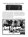
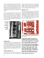
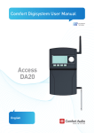
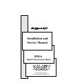
Installation and
Service Manual
DM-6
Digital Cinema Sound Adapter
THEATRE SYSTEMS
5945 Peachtree Corners East
Norcross, Georgia 30071
1 (800) 45-SMART or (404) 449-6698
Digital Magic Model DM-6 Digital Sound Adapter
4 Thumb screws will allow the front panel to be removed. This is generally done only one time duirng installation.
The SMART Model DM-6 Digital Magic Digital
Sound Controller is an interface unit designed to
connect the audio outputs from digital signal processors such as the DTS or Dolby DA20 to an existing sound system. It does not matter what stereo
processor you are now using. The outputs from your
stereo processor are simply disconnected from the
amplifier inputs and re-connected to the Optical
Inputs on the DM-6. The DM-6 outputs are then
connected to the amplifier inputs. The DM-6 will
then pass either the optical signals or the signals
2
from the digital processor to the amplifiers.
All switching is automatic, and there are manual as
well as automatic fallbacks to the optical processor
should the digital system or the DM-6 fail. The DM6 has been made as failsafe as possible. Once the
film is running, the operator does not have to do
any switching except in certain types of failures.
Block diagram shows overall signal flow.
Operation
Normally, there is no operator intervention required
to use the DM-6 except to initially set the volume
and to manually go to bypass during certain types
of failures. The DM-6 is running under the command of the digital processor, and changes between
digital mode and optical stereo are initiated by the
digital processor. If the digital processor no longer
sees a valid digital signal or timecode, then it will
tell the DM-6 to go to Optical mode. If the digital
processor or DM-6 fails but does NOT automatically go into optical mode, then the operator needs
to push the optical button on the DM-6 front panel.
If this still does not correct the problem, then the
operator must throw the toggle switch on the DM-6
front panel to the bypass position. This will force
the DM-6 into optical mode regardless of what the
lighted pushbuttons are telling you.
Installation
Locate the DM-6 close to the stereo processor and
the digital processor. There are 3 cable sets which
may be ordered with the DM6. One cable set is for
connecting the DTS digital system to the DM6, and
the other 2 are for the Dolby DA20.These cables
are about 30 inches long, so keep this in mind when
selecting a location. Also install any additional
power amps if needed at this time (e.g., for split
surrounds). The existing rack wiring harness may
have to be extended or re-wired to accomodate the
locations of the processors and to make new connections for any new amps. Install the power supply in the bottom of the rack and bring the power
supply wiring harness up to the top left terminals
INPUT CARD
The input card has two sets of input level controls for each
of two digital sources. This allows you to match the levels
between the players.
on the DM-6. Please note that the Plus Voltage lead
is red, the Minus Voltage lead is yellow, and the
Ground lead is black. Do not connect the leads incorrectly as damage could result !
Disconnect the outputs from the stereo processor
which go to the power amp inputs. These leads to
the power amps will now connect to the output terminals of the DM-6. Add any new leads as needed
for additional power amps.
Make a new wiring harness which will connect the
outputs of the stereo processor to the OPTICAL INPUTS on the top left terminal strip on the rear of the
DM-6. Please observe standard wiring practice, i.e.,
use 2 conductor + shield cable and ground the
shield at one end only.
ONE OCTAVE EQ (3)
SUB BASS EQ
DUAL ONE OCTAVE EQ
FOR SURROUND CHANNELS
FORMAT CARD
OUTPUT CARD
3
The first model of the DM-6 had on DB25 connector wired for the DTS
system.
The first production run of the DM6 has one DB25
connector on the rear panel. This may be used for
either the DTS or DA20 connection (with the appropriate cable) although the labeling on the front
panel pushbuttons indicates this input as the DTS.
The other digital input is labeled DIG on the front
panel pushbuttons. If both DTS and DA20 processors are being used on the same DM6, the the DA20
will have to be wired to the input terminal strip on
the DM6 while the DTS will plug into the DB25.
Now wire the digital processor outputs and control
lines to the appropriate inputs on the rear of the
DM-6. If you are using the DTS System and have
ordered the DTS to DM-6 cable from SMART, it is
only necessary to plug the cable in, and all connections are made for you. This cable, DM6-DTS,
has a DB50 plug on one end which plugs into the
mating connector on the DTS. The other end has a
DB25 plug which plugs into the DB25 receptacle
on the rear of the DM-6.
The second production run has an additional DB25
socket on the back of the p[roduct so that plugging
in both the DTS and the DA20 simultaneously will
be possible without having to wire directly to the
terminal strips.
If you are wiring a Dolby DA20, connections will
be made to either the DIGITAL INPUTS terminals
on the bottom right terminal strip or to the DB25
connector on the rear of the DM-6. The 2 DA20
cable sets are configured as follows:
The current models have two DB25 connectors. One is wired for
the DTS system and the other is for the Dolby DA20.
The DTS system is active when the front panel DTS button is lit. The
Dolby DA20 is active when the DIGITAL light is lit. TRhe OPTICAL
button may be pressed to return to the backup optical soundtrack
when necessary.
4
Additional digital inputs are provided for other systems. The signals
are connected to the individual terminals of the barrier strip. The
DB25 for the DA20 is wired in parallel with the input terminal strips.
DM6-DA20/1 DB25 on DM6 end to 2 DB25 on
DA20 end. This cable set allows easy plug-in o p eration. The 2 DB25’s on the DA20 end plug into
the Audio and Control connectors on the DA20.
DM6-DA20/2 Fanning strip for terminals on DM6
end to 2 DB25’s on DA20 end. The 2 DB25’s o n
the DA20 end plug into the Audio and Control connectors on the DA20.
Please refer to the DA 20 manual for other wiring
considerations. In particular, the Motor Start connector must be jumpered from Pin 1 to Pin 5. This is
explained in the DA20 Manual.
pins from the top of the Pink Noise Card on the
component side. In this configuration, the surround
switch on the Pink Noise Card will feed LS and RS
simultaneously, so you will have to turn the LS
Amplifier channel down while EQ’ing the the RS
channel and vice versa.
Next, play the test disc or film and set the auditorium levels as recommended by the digital processor manufacturer. Please note that the DM-6 has
several points in the signal path where the gain may
be adjusted. However, it is suggested that you make
all level adjustments on the digital processor itself,
and only use the internal trimpots on the DM-6 if a
normal level cannot be obtained.
DM-6 shown with 1/3 octave stage channel equalizers
Setup
It is necessary to feed pink noise at a 0.5 volt level
into each digital input in order to properly set the
EQ. Feed each channel and set the house EQ as
you normally would for an optical stereo processor. The easiest place to inject the Pink Noise is at
the Digital Inputs Terminal Strip on the rear of the
DM6. If you have already made connections to the
terminals, then just unplug the cable at the DTS or
DA20. Now you can feed these inputs with no loading on your Pink Noise source. After EQ is done on
all channels, just re-plug the connectors.
Alternatively, you can use your Smart Pink Noise
Generator card plugged into the left end slot to set
the EQ. First, remove the Input Switching Card,
and then plug in the Pink Noise card. It is necessary to remove the Input card because if both were
plugged in simultaneously, both cards would be
fighting for control of the signal buss. Please note
that the original Pink Noise card does not have LS
and RS outputs. It is necessary to modify the pink
noise card so that the one surround channel feeds
LS and RS. Simply add a jumper wire from Pin 4 to
Pin 5 on the Pink Noise Card. These are 4th and 5th
Please note that the DA20 Sub-Bass output is 10 dB
lower than the stage channels. The Sub-Bass channels on the DM6 Input Switching card have sufficient range to accomodate this lower level. The factory settings on the DM6 will already be set to compensate for this lower level on the second set of
digital inputs. The factory settings on the DM6 for
Trimpots on the OUTPUT CARD allow final level matching.
5
the first set of digital inputs will be set for DTS levels. If you hook a DA20 up to the first set of digital
inputs (i.e., you are connecting to the first or only
DB25 on the DM6), you will probably have to adjust the Sub-Bass level upward (using the Sub-Bass
trimpot on the DM6 Input Switching Card) to
accomodate the lower Sub-Bass level from the
DA20.
If you must make adjustments to the factory settings on the DM-6, then use the trimpots on the
INPUT SWITCHING card first. The top row of
trimpots is for the DTS DB25 inputs, and the bottom row of trimpots is for the DIGITAL INPUTS terminals. If this still does not give proper levels, then
use the OUTPUT card trimpots to get additional
range of adjustment.
source to the DM-6 signal path. It also contains
trimpots to adjust the signal levels if needed. These
trimpots will not normally require re-adjustment
from the factory settings except for the Sub-Bass
level as mentioned in the SETUP section.
Equalizer Card
The card shown is the full octave EQ card. Please
note that only the top half of the card is used for the
stage channels. Both top and bottom sections are
used for the split surrounds. The top is Left Surround
and the bottom is Right Surround. This same card is
also used for the optional SubBass EQ, but fewer
parts are installed. Optional 1/3 octave EQ cards
may be installed for stage channels.
The optional
sub bass
equalizer card
allows
smoothing of
the subwoofer
system
seperately
from the stage
channel
equalizers.
Dual one octave EQ card for split surround channels. Top set of pots
is Left surround channel. Frequencies are printed on the edge of the
card for each band.
Output Card
This card contains the VCAs and output gain stages.
The trimpots are used to vary the output signal levels which will feed the power amps. Do not adjust
these unless the digital processor level controls will
not give sufficient level. If necessary, set these while
the test disk or film is running to achieve the film
level recommended by the digital processor manufacturer.
Input Switching Card
This card receives the six audio channels from the
digital processors and switches the appropriate
6
Special factory made 3 foot cords are
available for the DTS 6-channel system
and the Dolby DA20 Digital. These cords
have a pre-wired DB 25 on one end and
fit the specific digital decoder on the
other end. All control and audio signals
are carried by the cord, and no additional
wiring is required. These cords may be
ordered by your SMART dealer. Cords
may be extended, when extra length is
required, by purchasing a standard computer cable with a DB25 on each end.
Make sure the cord has all pins wired.
Some computer cords do not.