1
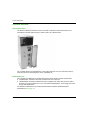
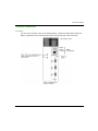
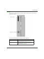
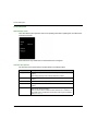
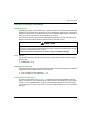
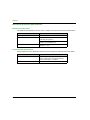
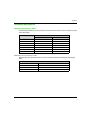
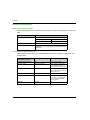
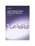
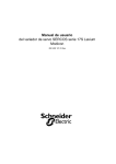
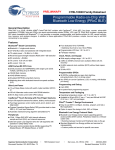
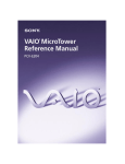
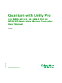
Quantum with Unity Pro 31001037 10/2014 Quantum with Unity Pro 141 MMS 425 01, 141 MMS 535 02 SERCOS Multi-Axis Motion Controller User Manual 31001037.05 10/2014 www.schneider-electric.com The information provided in this documentation contains general descriptions and/or technical characteristics of the performance of the products contained herein. This documentation is not intended as a substitute for and is not to be used for determining suitability or reliability of these products for specific user applications. It is the duty of any such user or integrator to perform the appropriate and complete risk analysis, evaluation and testing of the products with respect to the relevant specific application or use thereof. Neither Schneider Electric nor any of its affiliates or subsidiaries shall be responsible or liable for misuse of the information contained herein. If you have any suggestions for improvements or amendments or have found errors in this publication, please notify us. No part of this document may be reproduced in any form or by any means, electronic or mechanical, including photocopying, without express written permission of Schneider Electric. All pertinent state, regional, and local safety regulations must be observed when installing and using this product. For reasons of safety and to help ensure compliance with documented system data, only the manufacturer should perform repairs to components. When devices are used for applications with technical safety requirements, the relevant instructions must be followed. Failure to use Schneider Electric software or approved software with our hardware products may result in injury, harm, or improper operating results. Failure to observe this information can result in injury or equipment damage. © 2014 Schneider Electric. All rights reserved. 2 31001037 10/2014 Table of Contents Safety Information . . . . . . . . . . . . . . . . . . . . . . . . . . . . . About the Book. . . . . . . . . . . . . . . . . . . . . . . . . . . . . . . . Chapter 1 Product Description . . . . . . . . . . . . . . . . . . . . . . . . . . . . Controller Overview . . . . . . . . . . . . . . . . . . . . . . . . . . . . . . . . . . . . . . . Controller Components . . . . . . . . . . . . . . . . . . . . . . . . . . . . . . . . . . . . LED Indicators . . . . . . . . . . . . . . . . . . . . . . . . . . . . . . . . . . . . . . . . . . . Interfaces and Product Compatibility . . . . . . . . . . . . . . . . . . . . . . . . . . Controller Processor Boards . . . . . . . . . . . . . . . . . . . . . . . . . . . . . . . . Controller Drive/Memory Areas . . . . . . . . . . . . . . . . . . . . . . . . . . . . . . Chapter 2 Setup and Installation . . . . . . . . . . . . . . . . . . . . . . . . . . Setting the Modbus Plus Network Address . . . . . . . . . . . . . . . . . . . . . Installing the Controller . . . . . . . . . . . . . . . . . . . . . . . . . . . . . . . . . . . . The Battery . . . . . . . . . . . . . . . . . . . . . . . . . . . . . . . . . . . . . . . . . . . . . Resetting the SERCOS Multi-Axis Motion Controller . . . . . . . . . . . . . Appendices ......................................... Appendix A Appendix . . . . . . . . . . . . . . . . . . . . . . . . . . . . . . . . . . . . . Mechanical & Interface Specifications. . . . . . . . . . . . . . . . . . . . . . . . . Operational Specifications. . . . . . . . . . . . . . . . . . . . . . . . . . . . . . . . . . Electrical Specifications . . . . . . . . . . . . . . . . . . . . . . . . . . . . . . . . . . . . Index 31001037 10/2014 ......................................... 5 7 9 10 11 14 15 16 18 21 22 23 25 27 29 31 32 33 34 35 3 4 31001037 10/2014 Safety Information Important Information NOTICE Read these instructions carefully, and look at the equipment to become familiar with the device before trying to install, operate, or maintain it. The following special messages may appear throughout this documentation or on the equipment to warn of potential hazards or to call attention to information that clarifies or simplifies a procedure. 31001037 10/2014 5 PLEASE NOTE Electrical equipment should be installed, operated, serviced, and maintained only by qualified personnel. No responsibility is assumed by Schneider Electric for any consequences arising out of the use of this material. A qualified person is one who has skills and knowledge related to the construction and operation of electrical equipment and its installation, and has received safety training to recognize and avoid the hazards involved. 6 31001037 10/2014 About the Book At a Glance Document Scope This documentation acquaints you with the SERCOS Multi-Axis Motion Controller. It describes the motion controller, the setup, and installation, and the mechanical and interface specifications, the operational specifications, and the electrical specifications. Validity Note This documentation is valid for Unity Pro V8.1 or later. Related Documents Title of Documentation Reference Number Modicon Modbus Plus Network, Planning and Installation Guide 31003525 MMF Programming Overview Guide 890USE11300 M100S Series Servo Drive User Guide 890USE11400 Cyberline 1000S SERCOS Drive User Guide GI-CYBL-005 Cyberline 1000A System Design and Installation Manual GI-CYBL-002 Modicon Servo Motor Kit 890USE13900 You can download these technical publications and other technical information from our website at www.schneider-electric.com. 31001037 10/2014 7 8 31001037 10/2014 Quantum with Unity Pro Product Description 31001037 10/2014 Chapter 1 Product Description Product Description Introduction This chapter presents a product overview of the Quantum SERCOS multi-axis motion controller. What Is in This Chapter? This chapter contains the following topics: Topic Page Controller Overview 10 Controller Components 11 LED Indicators 14 Interfaces and Product Compatibility 15 Controller Processor Boards 16 Controller Drive/Memory Areas 18 31001037 10/2014 9 Product Description Controller Overview General Description The Quantum SERCOS multi-axis motion controller is a Quantum Automation Series CPU expanded to a double width housing to allow inclusion of a SERCOS link: The controller itself is an embedded PC, running Microsoft DOS 5.0. The controller’s memory areas and processor are designed to mirror a standard PC. Model Differences The controller is available in two models that support various motion network requirements: 141MMS42501: includes a 486, DX2 processor that runs at 66 mHz 141MMS53502: includes an expanded memory capability and a 586, DX5 processor with a speed of 133 mHz that allows you to run more extensive applications, such as high-axis count or large data applications. The differences between the two models are described at Quantum SERCOS System Specifications (see page 31). 10 31001037 10/2014 Product Description Controller Components Front View The front of the controller, shown in the following figure, contains the LED indicator panel, the battery compartment, three communications ports, and two fiber optic cable connectors: 31001037 10/2014 11 Product Description The table describes the front panel components: 12 Component Description of Function LED indicator panel Indicates the operating status of the controller and the fiber optic and Modbus communications networks it is connected to. (See LED Indicators (see page 14).) Battery Supplies backup power to the controller’s volatile SRAM. (See Replacing the Battery (see page 25).) Battery connector Connects the battery to the controller and allows for easy replacement of the battery Reset key switch Reinitializes the controller when operated by the companion key. (See the instructions for resetting the controller (see page 27).) Transmit connector Provides a receptacle for the fiber optic cable TX connector on a SERCOS network ring. Receive connector Provides a receptacle for the fiber optic cable RX connector on a SERCOS network ring. Modbus Comm 1 port Provides a nine-pin RS 232 D-shell female connector that can serve as either a Modbus port or a standard serial port. When used as a Modbus port, the controller can serve as either a master or slave. Modbus Comm 2 port Provides a nine-pin RS 232 D-shell female connector that can serve as either a Modbus port or a standard serial port. Modbus Plus port Provides a nine-pin RS 232 D-shell female connector that supports a single-cable Modbus Plus network 31001037 10/2014 Product Description Rear View The back of the controller, shown in the following figure, contains the rack connector and two decimal rotary switches: The following table describes the controller’s rear side components: Component Description of Function Rack connector A 68-pin socket that connects the controller to a Quantum rack. (See Installing the Controller (see page 23).) Decimal rotary switches Two rotary switches used to set the controller’s address on a Modbus Plus network. (See Setting the Modbus Plus Network Address (see page 22).) 31001037 10/2014 13 Product Description LED Indicators LED Indicator Panel The LED indicator panel provides continuous operating information regarding the controller and its associated networks: Each indicator is only visible when its associated LED is energized. Indicator Descriptions The functions of the LED indicators are described in the following table. 14 LED Indicator Description of Function Ready Lights green to indicate that the controller is powered up and operating properly. Blinks during power-up if the controller detects a problem. Run Lights green when the SERCOS fiber optic network ring is operating properly. Bat Low Lights red when the battery voltage is low or is not present. Modbus Lights green when Modbus communication is active and functioning properly. Modbus+ Blinks continuously at a rate of six times per second during normal Modbus Plus network operation. Blinks at various rates to indicate network detected error conditions, for more details refer to the Modbus Plus Network Planning and Installation Guide (see page 7). 31001037 10/2014 Product Description Interfaces and Product Compatibility Rack Requirements Depending on the type of CPU used in the PLC master module, two to six Network Option Modules (NOM) that communicate via the NOM protocol can be installed in a Quantum rack. The Quantum SERCOS multi-axis motion controller operates as one of the allowed NOM modules on the rack. It takes up two slots in the rack and can be installed in any location. For additional information regarding rack and backplane applications, refer to the Modicon TSX Quantum Automation Series Hardware Reference Guide, 840 USE 100 00.) CAUTION LOSS OF DATA Do not hot swap the Quantum SERCOS multi-axis motion controller. Hot-swapping the controller may produce corrupted data on the C: drive. Failure to follow these instructions can result in injury or equipment damage. Power Interface The Quantum SERCOS multi-axis motion controllers require diffent amounts of power from the Quantum rack: 141MMS42501: 2.5 A 141MMS53502: 3.0 A SERCOS Network Data Rate The SERCOS network protocol accommodates two different data rates depending on the address assignments of the Cyberline drive axes on the network. A rate of 2 MBaud for axis addresses 1 ... 50 A rate of 4 MBaud for axis addresses 51 ... 99 Communications Port Interfaces The three communication ports (see page 11) supplied with the Quantum SERCOS multi-axis motion controller allow you to interface with a variety of devices. The Modbus Plus port provides access to a host of diverse Modicon products over the Modbus Plus network. The two Modbus communication ports (Comm 1 and Comm 2) can serve as either Modbus ports or as standard RS 232 ports. 31001037 10/2014 15 Product Description Controller Processor Boards Overview The Quantum SERCOS multi-axis motion controller contains three printed circuit boards. Each board plugs in to connectors on the module’s internal ISA interface. A brief description of each board is given below. Processor Board The processor board contains the microprocessor, memory area, A and C drives, and associated control circuits. This board, in essence, contains all the features of a standard PC. Interface Board The interface board carries the communication circuits for the three communication ports and for the backplane. It also contains the digital rotary switches for Modbus Plus network addressing, the battery compartment, and reset switch. SERCOS Board The SERCOS board carries the fiber optic receive and transmit circuits for communication with the Cyberline servo drives. The TX (transmit) and RX (receive) fiber optic connector receptacles are mounted on this board. Backplane Interface to Controller The module plugs into the Quantum rack via a 68-pin socket attached to the rear of the interface board. Address and data information to/from the three printed circuit boards is facilitated via the internal ISA interface. In addition, address and data information is distributed to/from the PLC via the backplane connector on the Quantum rack. 16 31001037 10/2014 Product Description Block Diagram The figure shows a functional block diagram of the Quantum SERCOS multi-axis motion controller module: 31001037 10/2014 17 Product Description Controller Drive/Memory Areas Introduction The memory and storage areas in the motion controller are designed to mirror a PC with the exception that the controller’s A: and C: drives are actually part of the memory and not physical drives like a PC. The flash memory is the controller’s A: drive, and the SRAM is the controller’s C: drive. Dynamic RAM, which is comparable to the conventional memory in a PC, is the controller’s third storage area. This design makes for: Easy storage Power up like a standard PC Booting via a customized BIOS An MS-DOS environment on the controller Easy communication with other automation components The motion controller’s three memory areas are described below. A: Drive (Read-Only Flash Memory) The read-only flash memory is configured as the controller’s A: drive. It is initialized at the factory and contains several system files, including the MS/DOS command processor (COMMAND.COM), configuration and initialization files, DOS disk formatting and checking utilities, and a line editor. C: Drive (SRAM Memory) The read/write, battery backed, static RAM (SRAM) memory area in the motion controller is known as the C: drive. It emulates and interacts with the user like the hard-disk C: drive in a PC. Unlike the controller’s read-only A: drive, you can write data to the C: drive. It is shipped to you unformatted and you must format it with Modicon’s Quantum Advanced Motion Operating System (AMOS) before you can download your motion application programs. See the MMF Programming Overview Guide, 890 USE 113 00, for information on installing AMOS. The controller’s battery ensures that files stored in the volatile C: drive are maintained in the event of a power outage or power cycle. NOTE: If it becomes necessary to restore an application program, be aware that the restoration process will automatically reformat the C: drive and overwrite AMOS with the version that was on the controller when the backup was performed. Dynamic RAM Memory The motion controller’s dynamic RAM memory is comparable to the memory (conventional, extended, and upper) in a PC. It is used to run AMOS and your motion application programs. 18 31001037 10/2014 Product Description Holding Registers The Quantum SERCOS multi-axis motion controller provides non-volatile holding register memory for communication with other external devices. See the MMF Programming Overview Guide (890 USE 113 00) for information on the use of the controller’s holding registers. Memory Configurations The table presents the memory capacities for the SERCOS multi-axis motion controllers: Memory Type 141MMS42501 141MMS53502 Drive A (read only) 500 kbytes 500 kbytes Drive C (read & write) Dynamic RAM Holding Register 31001037 10/2014 2000 kbytes 4000 kbytes Conventional 640 kbytes 640 kbytes Extended 7168 kbytes 7168 kbytes Upper 384 kbytes 384 kybtes 10,000 words 60,000 words 19 Product Description 20 31001037 10/2014 Quantum with Unity Pro Setup and Installation 31001037 10/2014 Chapter 2 Setup and Installation Setup and Installation Introduction This chapter describes how to set the Modbus Plus network address, install the SERCOS multiaxis motion controller in a Quantum rack, replace the battery, and reset the controller. What Is in This Chapter? This chapter contains the following topics: Topic Page Setting the Modbus Plus Network Address 22 Installing the Controller 23 The Battery 25 Resetting the SERCOS Multi-Axis Motion Controller 27 31001037 10/2014 21 Setup and Installation Setting the Modbus Plus Network Address Switch Settings for Modbus Plus Each device on a Modbus Plus network must be assigned a unique address in the range 01...64. Two decimal rotary switches are located on the back of the Quantum SERCOS multi-axis motion controller: Setting the Controller’s Address Switch SW1 (the top switch) sets the most significant digit (tens) and SW2 (the bottom switch) sets the least significant digit (ones) of the Modbus Plus address. In the following figure, the switches are set to a Modbus Plus address of 24: NOTE: Setting the switches to a value of 00 or any value greater than 64 is not allowed. If you do so, an illegal Modbus Plus address error will be generated and the Modbus+ indicator on the LED indicator panel will light steadily. NOTE: Schneider Electric recommends that you reserve address 64 for future network maintenance. Be aware that address 1 is often used as the default address of the controller node’s programming panel. 22 31001037 10/2014 Setup and Installation Installing the Controller Quantum Rack Characteristics of Quantum racks: Quantum racks are mechanically secure and electrically connect all modules that are mounted to them. A Quantum rack contains a passive circuit board that permits modules to communicate across the backplane and identify their slot numbers without further switch settings. Quantum racks are available in six different sizes ranging from 2 to 16 slots. NOTE: For more information about Quantum rack assemblies refer to Appendix C in the Modicon TSX Quantum Automation Series Hardware Reference Guide (840 USE 100 00). Quantum Four-Slot Rack The Quantum SERCOS multi-axis motion controller is a double-width Quantum module that can be inserted into any two slots in a Quantum rack. Since a Quantum power supply must fill one slot, a three-slot rack is the minimum size required for the motion controller if no optional PLC is planned. A four-slot rack is necessary when an optional PLC is included: Schneider Electric recommends that the Quantum power supply be installed in the first or last slots in the rack. Before Installation Before you install the controller: Choose a rack in which to mount the controller. Ensure that two adjacent slots are available in the rack. You need a medium-sized Phillips head screwdriver. 31001037 10/2014 23 Setup and Installation Mounting the Controller on the Rack To mount the SERCOS multi-axis motion controller in a Quantum rack: Step 1 24 Action Hold the module at an angle and mount it on to the two hooks located near the top of the rack: 2 Swing the module down so its connector engages the rack connector. 3 Using a Phillips head screw driver, tighten the screw at the bottom of the module between 2 and 4 in-lbs of torque. 31001037 10/2014 Setup and Installation The Battery About the Battery A non-rechargeable lithium backup battery is located in the battery compartment housing, which is mounted to the interface board. It is accessible from the front of the controller (see page 11). The battery maintains the volatile SRAM memory when power is removed from the Quantum SERCOS multi-axis motion controller. Typically, the battery can maintain power to the SRAM memory for up to six months with no power applied to the controller. The Bat Low LED The red Bat Low indicator on the LED panel will light when: the battery charge is low a replacement battery is needed the battery is not present in the controller NOTE: The battery should be changed within seven days from the time the Bat Low LED comes on. Read and follow the Battery Replacement Procedure, described below, to avoid loss of data from occurring to the controller’s storage areas. Part Number Your Schneider Automation supplier carries replacement batteries under part number 043502625: Remove the new battery from its packing bag and proceed with the following installation instructions. 31001037 10/2014 25 Setup and Installation Battery Replacement Follow these instructions to remove the old battery and install the new one. CAUTION LOSS OF DATA Ensure that power is applied to the controller before replacing the battery. Replacing the battery while power is removed from the controller results in corrupted programs and lost data on the C: drive and in the 4x holding registers. Failure to follow these instructions can result in injury or equipment damage. Replace the old battery with a new one: Step Action 1 Open the door on the front of the controller to expose the battery compartment 2 Push upward on the holding tab in the battery compartment and slide the battery out of the housing. 3 Unplug the battery connector from the two-pin socket located just above the reset switch. 4 Set the old battery aside. 5 Plug the new battery’s connector into the two-pin socket in the battery compartment housing. 6 Insert the plus (+) terminal end of the new battery into the housing and slide it all the way in until the holding tab engages. 7 Dispose of the old battery in accordance with local requirements. Ensure that the battery has been replaced properly: 26 Step Action 1 Check the Bat Low indicator on the LED panel. 2 If the indicator is still lit, check whether the battery is backwards (see Step 6 in the preceding procedure). 3 If the battery is installed correctly, and the Bat Low indicator remains on, remove the existing battery and replace it with a known good battery. 4 If the problem still persists, contact your Schneider Automation customer representative. 31001037 10/2014 Setup and Installation Resetting the SERCOS Multi-Axis Motion Controller Using the Reset Key Switch Your motion controller is designed so that it can be reset in much the same manner as a PC, that is, using the reset button to reboot the system. In the case of your controller, the reset button is replaced by a key. Actually, you should have received two identical keys (the second one is a spare) packaged with your controller. Use the key to reinitialize the system software, when necessary, without removing and reapplying (cycling) the power to the controller. Resetting the Controller To reset the controller, proceed as follows Step Action 1 Open the door on the front of the controller. 2 Insert the key into the reset key switch located in the battery compartment. 3 Turn the key clockwise 90 degrees to its reset position. 4 Turn the key counterclockwise 90 degrees back to its original run position. 5 Remove the key from the reset key switch. About the Key NOTE: Return the key to its run position immediately after turning it to the reset position, otherwise the system will continuously reboot. NOTE: Do not use the reset key switch to boot the system after upgrading the BIOS. A BIOS upgrade requires a complete power cycle (removing and then reapplying power to the controller) and cannot be accomplished with the reset key switch. 31001037 10/2014 27 Setup and Installation 28 31001037 10/2014 Quantum with Unity Pro 31001037 10/2014 Appendices 31001037 10/2014 29 30 31001037 10/2014 Quantum with Unity Pro Appendix 31001037 10/2014 Appendix A Appendix Appendix Introduction This chapter contains the system specifications for SERCOS multi-axis motion controllers. What Is in This Chapter? This chapter contains the following topics: Topic Page Mechanical & Interface Specifications 32 Operational Specifications 33 Electrical Specifications 34 31001037 10/2014 31 Appendix Mechanical & Interface Specifications Mechanical Interface Table This table lists the SERCOS multi-axis motion controller’s mechanical and interface specifications. Mechanical Feature Specification Assembly Dual-Width Quantum Slot Connectors Two SERCOS fiber optic connectors: TX (transmitter) RX (receiver) Three DB9 (nine-pin) connectors: Modbus Comm 1Modbus Comm 2Modbus Plus Switches Two BCD rotary switches (Modbus Plus node addresses 1 ... 64) System Interface Specifications System interfaces for the SERCOS multi-axis motion controller are described in the table below. 32 System Interface Description SERCOS communication interface Can be configured for any (1 254) servo drive-axis address. Supports fiber-optic based SERCOS protocol operating at 2 or 4 Mbaud. Quantum backplane interface As a network option module (NOM). 31001037 10/2014 Appendix Operational Specifications Operational Specifications Tables Operational Specifications for both models of the SERCOS multi-axis motion controller are given in the table below: Controller Features Controller Model Specifications 141MMS42501 141MMS53502 Processor 486DX2 66 mHz 586DX5 133 mHz DOS MS ROM DOS 5.0 MS ROM DOS 5.0 Conventional memory 640 kbytes 640 kbytes Extended memory 7,168 kbytes 7,168 kbytes Drive A (read only) 500 kbytes 500 kbytes Drive C (read & write) 2,000 kbytes 4,000 kbytes Non-volatile memory 10,000 words 60,000 words SERCOS Protocol Capacities Table SERCOS protocol capacities common to both controller models are described in the following table: SERCOS Protocol Capacities—common to both controller modules Addresses 1 254 Baud rate 2 or 4 Mbaud (software configurable) Cycle time 1...15 msec, configurable 2 ms for 8 axes, typical Rings 1 31001037 10/2014 33 Appendix Electrical Specifications Electrical Specifications Tables Electrical specifications for the SERCOS multi-axis motion controller are described in the following table. Electrical Feature Specification Power Requirements From Quantum backplane 141MMS42501 141MMS53502 + 5V at 2.5 A maximum + 5V at 3.0 A maximum Optical light output reception Conforms to SERCOS specification Battery Non-rechargeable lithium battery that maintains volatile SRAM memory for up to 6 months. Assembly part number 043502625 Electromagnetic Specifications Table Electromagnetic specifications for the SERCOS multi-axis motion controller are described in the following table. 34 Electromagnetic Susceptibility Feature Reference Industrial Radiated noise emission N/A Factory floor exempt Transient surge IEC 801-5 (level 2) 0.5 kV surge, comm. ports 2.5 kV shield to ground 2.0 kV common, 1kV normal Fast transients IEC 801-4 MB: 0.5 kV MB+, SERCOS 2 kV Through pwer supply 2 kV Surge withstand (ringwave) IEC 255 (IEEE) 472) 2.5 kV inductive coupled Electrostatic discharge IEC 801-2 8 kV, air, 10 discharges 4 kV, contact, 10 discharges 8 kV, horizontal & vertical coupling planes Ringwave IEC 255 2 kV 31001037 10/2014 Quantum with Unity Pro Index 31001037 10/2014 Index 0-9 R 141MMS42501, 10 141MMS53502, 10 reset, 27 B battery, 25 S setting the address, 22 specifications, 31 C circuit board, 16 connectors battery, 26 Comm 1 port, 15 Comm 2 port, 15 power, 15 D data rates, 15 I installation, 21 M memory, 18, 18, 18, 18, 19, 19 Modbus Plus address, 22 P physical description, 9 power consumption, 15 Q Quantum SERCOS multi-axis motion controller, 9 31001037 10/2014 35 Index 36 31001037 10/2014