1
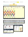
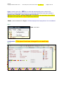
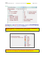
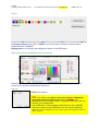
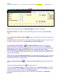
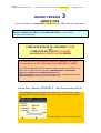
ARIANE.
Copyright Claude HOCHET 2013
Time stamp of this version of the manual: 2013 March 25
ARIANE VERSION
USER’S TIPS
Page 1 sur 41
3
(as of 2013 March the current public release is Ariane V3 till V4 is also made public)
THIS ARIANE VERSION ALLOWS YOU (almost) TOTAL MASTERY ON CORDAGE
ROUTE, CODING PATTERN and COLOURS PATTERN ( see this article
http://tinyurl.com/cdh7gca )
MAIN ADDITIONS: TOOL BOXES FOR
COMPLETE EDITION OF CROSSING TYPES
and
COMPLETE EDITION OF COLOURS
PLUS MANUAL PINS PLACING MODE
You will still need to study the VERSION 2 MANUAL as in this
document we see ONLY what has been CHANGED or ADDED.
You cannot realistically hope to make do without it (unless you already are an
expert with this V2 and with the domain of NESTED-BIGHT CYLINDRICAL
KNOTS plus REGULAR and SEMI-REGULAR C.K ! )
The first 30 pages in this V2 manual contains many teachings about those
NESTED-BIGHT knots that you will need to know.
Link to User_Manual_VERSION 2 : http://tinyurl.com/ckr5z32
THIS VERSION HAS A WHOLE COLLECTION OF “ TOOL TIPS” : let the
MOUSE INDEX POINTER hover over a word or an icon and you will get” a
tip”
Here hovering on the word Asymmetric
ARIANE.
Copyright Claude HOCHET 2013
Time stamp of this version of the manual: 2013 March 25
ARIANE
Fig 1 full screen window. Quite a lot of change since V2
Fig 2
Fig 3
File three items : Open, Save and Exit
Save & Quit are self-explaining.
Fig 4 FILE
Page 2 sur 41
ARIANE.
Copyright Claude HOCHET 2013
Time stamp of this version of the manual: 2013 March 25
Page 3 sur 41
Open is used to open the . ARI file of a knot that was saved by user or sent to him.
ARI files are a light, swift and powerful tool of exchange with others knots tyers owning a
licensed copy of ARIANE. ( very useful to archive knots too )
ARI format has evolved, ARI files made with V1 and V2 can be opened by Ariane V3 but
ARI made with Ariane V3 can only be opened by Ariane V3.
Edition (here numbered 2 in Fig 3) In V2 that stayed just an empty box so it is now deleted.
Fig 5
Tools : two items
Configuration :
Fig 6
This panel has been changed in no small way.
ARIANE.
Copyright Claude HOCHET 2013
Time stamp of this version of the manual: 2013 March 25
Page 4 sur 41
Fig 6-a
The standardised, normal for RIGHThanded persons, direction for ODD-NUMBERED H-P is
BOTTOM RIGHT to TOP LEFT. (For LEFThanded person the normal direction is BOTTOM
LEFT to TOP RIGHT . All other directions are ABERRANT’.)
DO NOT FORGET TO ALWAYS SET THE CORRECT WORKING
DIRECTORY as files will be saved into the folder indicated here.
Fig 6-b
Open your Ariane a first time, close it then open it again: the language
should then be the language of your Windows Operating System.
ARIANE.
Copyright Claude HOCHET 2013
Time stamp of this version of the manual: 2013 March 25
Page 5 sur 41
Fig 6-c
Crossing Colours :From LEFT to RIGHT : this is the order in which the colours will be
attributed to the STRANDS.
Background is for choosing the background colour of the GRID area.
Fig 6-c-bis How to modify the choice of colours.
Clicking on a “coloured square” will open a panel which will allow you to attribute a new
colour to the “square” that has been clicked on.
Fig 6-d
Cancel is obvious
OK is the button you NEED TO ACTIVATE IN ORDER TO MEMORIZE
Using the ; X ; on red
background at the top right corner of the panel will close it but you
will lose your modifications.
Any modification of the language needs that you close ARIANE
and open it again so the modification can be ‘saved’ and acted
upon. All other modifications are acted upon immediately inside the
same session.
WHAT WAS DONE IN CONFIGURATION.
ARIANE.
Copyright Claude HOCHET 2013
Calculator: Fig 7
Time stamp of this version of the manual: 2013 March 25
Page 6 sur 41
GIVEN “ AS IS”
Fig 8
HELP
Fig 9
same as in V2
same as in V2
N°5 Open : Open the working directory.
N°6
Save in the designated working directory a file in
.ARI file format that contains the knot’s
characteristics and can be open again in Ariane:
It is the privileged mean to exchange knots or to
archive them.
N°7
The ‘instant tutorial’ : writes a .PDF file that
contains the table of HP codes and the knot grid as
it is on the screen. (see the Tutorial for a 96 FACEs spherical cover made by Claude
HOCHET using grid and the table of HP coding produced by ARIANE).
ARIANE.
Copyright Claude HOCHET 2013
Fig 10
Time stamp of this version of the manual: 2013 March 25
Page 7 sur 41
same as in V2
N°8 Makes a copy of the grid to the clip board.
N°9 Print may be this one will be suppressed.
Fig 6
N°10 .
Traces the COLUMNS and ROWS LINES.
N°11 Shows (or not ; by inversion of the situation) the
PINs notation.
N°12 Shows (or not ; by inversion of the situation) the
crossings.
N°13
Inverts the crossings U for O and O for U
N°14
Changes the orientation of the traced grid, of the IMAGE of it only : PORTRAIT / LANDSCAPE or
VERTICAL CYLINDER FRAME OF REFERENCE / HORIZONTAL MANDREL FRAME OF REFERENCE
Fig 11
same as in V2
N°15
.
N° HP , Number of the HALF-PERIOD.
N°16
Start PIN and Arrival PIN for the HP.
ARIANE.
Copyright Claude HOCHET 2013
Time stamp of this version of the manual: 2013 March 25
Page 8 sur 41
same as in V2 ( here standardised or NORMAL
direction of ODD numbered HP is the choice made )
Fig 12 the PINs notation.
The numbering is PIN number – BIGHT-RIM number.
4 - 6 means 4th PIN on the 6th BIGHT-RIM.
ARIANE.
Copyright Claude HOCHET 2013
Fig 13
Time stamp of this version of the manual: 2013 March 25
Page 9 sur 41
same as in V2
N°17 This is the ‘POST-IT’’ icon just like in RKnot
Builder.
N°18
This is one « quits » the application.
Fig 14 THE POST-IT.
same as in V2
Post-it is useful when in STEP by STEP mode when making a knot.
ARIANE.
Copyright Claude HOCHET 2013
Time stamp of this version of the manual: 2013 March 25
Fig 15 the contextual menu. Changes
Page 10 sur 41
were made here too.
The CONTEXTUAL MENU can be opened with a RIGHT mouse click in the main area of the
window.
The first « block”: ISO, ISO1 and Square gives the opportunity of choosing the type of the
TRACING GRID that will be used.
The second block is for the choice of the width or thickness of the lines traced.
The third ‘block’ gives the choice of
*** the Font Size.
*** Saving the knot on screen in a .ARI format file
*** Copy : copy the image of the grid to the clipboard. You can then paste it in image
manipulation software.
A fourth block offers the setting (also in Configuration Panel) of the background colour of
the grid area.
The LENGTH OF CROSSINGS can be MODIFIED BY USING THE MOUSE WHEEL while the
mouse pointer is positioned inside the grid frame.
ARIANE.
Copyright Claude HOCHET 2013
Time stamp of this version of the manual: 2013 March 25
Fig 16 (top left hand side of the window. ) much
Page 11 sur 41
changes were made here.
Regular: Regular Symmetric Nested-Bight Cylindrical Knot -
report yourself to V2
manual ( even V1 ) for definition.
ASYMMETRIC: Regular Asymmetric Nested-Bight Cylindrical Knot -
report
yourself to V2 manual ( even V1 ) for definition.
ARI files NEW.
This choice is for when you want to load a knot of which you already
have the user created ARI file ; knot will open “directly”.
When an ARI file is opened a panel open as shown in Fig 16 bis.
This panel is closed by clicking on the …X… in the top right side of the grey panel.
As in V2 if case HP Coding is checked then instead of the grid it is the HP after HP table
of crossing coding which is put on screen.
ARIANE.
Copyright Claude HOCHET 2013
Time stamp of this version of the manual: 2013 March 25
Page 12 sur 41
Fig 16 bis opening an ARI file
ARI files can now be commented and signed with the name of their author.
An URL can be indicated.
While using an ARI file you may open again the INFORMATION Panel with a LEFT mouse
click on the NAME of the ARI but you will not be able to make any modification in that panel
at that stage ; modification are to be made only during the SAVING of the ARI.
Slide-Ruler : NEW. This addition allows user to change the size of the drawn grid
The rest:
Bight-Nest, Bight, Spacing, Top Edge Bight Offset and HP Coding are
exactly like in V2
1 and V2 :
Those fields are just as they were in V
Bight-Nest
Bight (in a nest)
SPACING or Schaake’s distance ‘x ‘ : the distance in ROW INTERVAL(vertical cylinder frame
of reference) between the two innermost BIGHT-RIM.
Top Edge Bight OFFSET (a bit different from Schaake’s DELTA for those knots.)
ARIANE.
Copyright Claude HOCHET 2013
Time stamp of this version of the manual: 2013 March 25
Page 13 sur 41
Users make their entries in those fields using the “UP & DOWN” arrows.
Fig 17 (top middle left ) NEW
Standard mode : this is the usual or
‘normal’ mode in which users enter the
parameters using the Up&Down arrows
Step by Step : This run Half-Period after
Half-Period of a knot fully made and on screen
Of course the HP orientation chosen in
Configuration is at work here.
You can also do a Step by Step which is
STRAND by STRAND instead of HP by HP with
CTRL + LEFT mouse click
Edit crossings : NEW. In this mode you
can edit in a multi-form manner the TYPE and COLOURS of the crossings
Pins Placing : NEW. In this mode you manually enter the pins at the proper places
(determined by your planning of the knot ) to create a grid.
ARIANE.
Copyright Claude HOCHET 2013
Time stamp of this version of the manual: 2013 March 25
Fig 18 (top middle right ) ENTIRELY
Page 14 sur 41
NEW
Column
Row
This modify the CODING PATTERN by
a « set sequence ».
Instead of the Up & Down arrows you
may activate the field by positioning the
index in it and use
CTRL + Mouse Wheel to increment or
decrement the number entered.
Icon 1: Automatic colouring, each
CROSSING takes the colour of the
STRAND making the OVER
Icon 2 : All crossings are coloured in
the ‘base” blue.
Icon 3 : Reset matrix to (all changes
are lost)
.U1-O1
.all crossings are coloured in basic blue
Fig 18 annex
ENTIRELY NEW
In the three grids in Fig 18 annex the parameters : bight-nest, bight, Spacing, Offset, and
setting of Column are EXACTLY THE SAME, they are unchanged but the grid DISPOSITION
OF CROSSINGS is changed by changing the “starting point of the application” of the setting
with 3 value for Column.
This starting point is modified by putting the mouse pointer in the drawing area and using
(slowly ! ) CTRL + MOUSE WHEEL
ARIANE.
Copyright Claude HOCHET 2013
Time stamp of this version of the manual: 2013 March 25
Fig 19 (top right hand side of the windows)
Page 15 sur 41
same as in V2
Results are shown here as in V2, they were just moved there.
Lead .
Faces == a Face may be made with several crossings.(Xing) )
Crossings
Bight
Over = OVER Xing
Under = UNDER Xing
Nb HP == NUMBER OF HALF-PERIODS.
Nb of Strand == NUMBER OF STRANDS (can be single strand or multi-strand.)
Width = of the grid
Height = of the grid ( help for Pin Placing for example )
ARIANE.
Copyright Claude HOCHET 2013
Time stamp of this version of the manual: 2013 March 25
Page 16 sur 41
PINS PLACING MODE
This is the ONLY WAY TO MAKE knots that are not amenable to the automated
treatment: in other words knots THAT DO NOT BELONG TO
-
REGULAR CYLINDRICAL
SEMI-REGULAR CYLINDRICAL
REGULAR SYMMETRIC NESTED-BIGHTS CYLINDRICAL
- REGULAR ASYMMETRIC NESTED-BIGHTS CYLINDRICAL
Please refer to V2 user’s manual for details.
A few examples of knots that CANNOT be made WITHOUT MANUAL
PINS PLACING :
ARIANE.
Copyright Claude HOCHET 2013
Time stamp of this version of the manual: 2013 March 25
Page 17 sur 41
ARIANE.
Copyright Claude HOCHET 2013
Time stamp of this version of the manual: 2013 March 25
Page 18 sur 41
ARIANE.
Copyright Claude HOCHET 2013
Time stamp of this version of the manual: 2013 March 25
Page 19 sur 41
Fig 20 window in PINS PLACING mode NEW
This is how the screen is when the PINS PLACING radio button is selected.
Deletion button : the grid is reset, the drawing is lost but you stay in Pins Placing
mode.
Icon opening yellow folder :
loading an existing file for working on it again or for
modification.
At regular interval “intermediate files” are saved during the making of a grid. Look for them in
the directory that has been set in Configuration as Working Directory.
Icon floppy disk image :
An automated Back-up of the knot in progress
without exiting the “pins placing” mode is at work, those files are saved in the Working
Directory you have defined in Configuration Panel. From the first pin placed a file is saved :
SauvegardeTmp0.Ari ; after that every 4 pins a file is save with the rank “x’ being
incremented by ‘1’: SauvegardeTmp’x’.Ari till ’x’ = 15 (16 files saved ) then it is again a cycle
from “0”.( NO WARNING is given that a new cycle is beginning and that the previous file of
same name is replaced ).
Each time you enter the Pins Placing mode the saving starts anew with x = 0 so if you want
to keep the existing files existing prior to that new session of Pins Placing mode put them
where they will be safe or rename them.
Using the floppy disk image
grid.
you make your own voluntary saving of the state of the
Those files can be load again using
the folder open icon.
If when in Pins Placing mode you check the radio button for Standard mode then the knot
in progress is lost, when in Normal or Standard screen you have on the screen the current
knot that was there when you went to Pins Placing mode.
Still the SauvegardeTmp’x’.Ari files that were saved are still available in the Working
Directory.
ARIANE.
Copyright Claude HOCHET 2013
Icon of floppy disk
Time stamp of this version of the manual: 2013 March 25
Page 20 sur 41
image plus Ends : Back-up the current knot (in progress)
and return Ariane to Standard Mode putting on screen the built knot.
Tracing on : if the cell is checked then Automatic tracing is ON.
In the Configuration Panel you may chose the option of always beginning:
EITHER with Automatic tracing is ON when the cell is checked
OR with Automatic tracing is OFF when the cell is unchecked.
LET US SEE SOME NOTIONS THAT ARE NECESSARY FOR THE MANUAL
POSITIONING OF THE PINS (much more details are in V2 User’s manual)
Fig 21
The fast and sure way to get a correct drawing and to get the grid measurements is to use an
ISOMETRIC GRID.
ARIANE.
Copyright Claude HOCHET 2013
Time stamp of this version of the manual: 2013 March 25
Page 21 sur 41
Fig 22 mode PINS PLACING window
REMEMBER THIS POINT :
PINS PLACING MUST ABSOLUTELY COMPLY with the
HP ORIENTATION SET in the CONFIGURATION Panel.
( orientation of the ODD NUMBERED HP in each case )
This chosen ORIENTATION WILL ALSO APPLY TO HOW THE NUMBERING OF THE
PINS IS DONE (never forget to EXPLICITLY state your chosen orientation when
exchanging knots)
ARIANE.
Copyright Claude HOCHET 2013
Time stamp of this version of the manual: 2013 March 25
Page 22 sur 41
BOTTOM RIGHT – TOP LEFT ( the standard one --normal for right handed
persons.)
BOTTOM LEFT –TOP RIGHT (normal for left-handed persons)
And the two ‘ABERRANT’ (if interested, read http://tinyurl.com/cgzj778
in particular page 7 : handedness and how humans function)
TOP LEFT –BOTTOM RIGHT
TOP RIGHT – BOTTOM LEFT
Fig 23
There are TWO WAYS to place the pins :
*** With AUTOMATIC TRACING of the HP “ON” (case checked)
*** With AUTOMATIC TRACING of the HP “OFF” (case unchecked)
ARIANE.
Copyright Claude HOCHET 2013
Time stamp of this version of the manual: 2013 March 25
Page 23 sur 41
When tracing is “ON” then you must work with method and order: enter the HP in their
normal order of development ( do not forget the orientation set in Configuration Panel ) and
comply with the numbering of the BIGHT-RIMS on each KNOT BORDER. ( see again V2
manual if you are lost here ).
When tracing is “OFF” (counseled only for the most adept with Ariane and knowledgeable
about nested-bight C.K! ) then you enter the pins in the proper place but in the order you
want.
TRACING OF THE HP “ON”
Fig 24 Placing the first pin ( HP orientation BOTTOM RIGHT – TOP LEFT )
Words to the wise :
*ALWAYS* prepare a paper
plan of your knot
(use Isometric grids if you want
it easy) to get your
measurement and the tracing
you want, ARIANE cannot
works intelligently if you are not,
yourself, giving intelligent
orders.
In Fig 24 the first pin was
entered (complying with HP
orientation) at the BOTTOM
RIGHT by positioning the
mouse pointer at the chosen
place and making a left click
(another left click on a pin
already existing will erase it and
delete what putting that pin in
place had yielded)
Placing the pin immediately
results in having the HP traced
to the very top BIGHT-RIM as
can be seen in Fig 24.
Now, according to your
prepared grid, you place the “arrival pin” at the meeting of the BIGHT-RIM of interest and of
the “proposed” HP: this is what was done in Fig 25 with the result that the HP between the
two last pins placed is now ‘confirmed and is in “full thickness” and the following “proposed”
HP is traced.
And so on….
ARIANE.
Copyright Claude HOCHET 2013
Time stamp of this version of the manual: 2013 March 25
Page 24 sur 41
Clicking on that already placed ”arrival pin” will erase it and allow the correction of a mistake.
To erase the whole grid use the DELETION button.
To save the grid “in the making” use the proper icon.
It is possible to double the length and width of the grid (without changing the number of
“units”) by putting the mouse pointer on it and using ALT + Left mouse CLICK.
Fig 25 placing the second pin
ARIANE.
Copyright Claude HOCHET 2013
Time stamp of this version of the manual: 2013 March 25
Page 25 sur 41
Fig 26 Using PINS PLACING mode to make the blue grid height=12 width=16
Fig 26 bis
Using Fig 26 you can easily
imagine what is happening on the
screen.
It is suggested that you do that
grid as a training exercise.
Fig 26 bis is the template you are
supposed to have prepared on
paper using an isometric grid.
When you are finished with placing
all you pins then use the
icon to return to
Standard mode while saving the
.ARI file of your grid.
If you are not finished use the
other floppy disk
icon to save
an intermediary .ARI file that can
be completed later.
ARIANE.
Copyright Claude HOCHET 2013
Time stamp of this version of the manual: 2013 March 25
Page 26 sur 41
TRACING OF THE HP “OFF”
As the tracing is OFF you may not stay constrained to follow a HALF-PERIOD by HALFPERIOD order but place the PINS BIGHT-RIM after BIGHT-RIM
The hard way is to place each pin in turn or “ONE BY ONE”.
The easy way (IFF you have a really good isometric grid prepared and verified) is to use the
“automated pacing ” of pins placing.
On each BIGHT-RIM (remember that you must comply with the orientation of HP set in
CONFIGURATION Panel, the numbering of the pins will follow that setting too)
---------------------------------------BOTTOM RIGHT – TOP LEFT ( the standard one -- for RIGHT-handed persons.)
Pins are placed on each BIGHT-RIM from RIGHT to LEFT - the ODD numbered HP starting
on one BIGHT-RIM at the BOTTOM KNOT EDGE and arriving on one BIGHT-RIM at the
TOP KNOT EDGE
---------------------------------------BOTTOM LEFT –TOP RIGHT ( for LEFT-handed persons)
Pins are placed on each BIGHT-RIM from LEFT to RIGHT - the ODD numbered HP starting
on one BIGHT-RIM at the BOTTOM KNOT EDGE and arriving on one BIGHT-RIM at the
TOP KNOT EDGE
---------------------------------------And the two ‘ABERRANT’ (if interested, read this piece in particular page 7 :
handedness and how humans function to understand the ‘aberrant”)
---------------------------------------TOP LEFT –BOTTOM RIGHT
Pins are placed on each BIGHT-RIM from LEFT to RIGHT - the ODD numbered HP starting
on one BIGHT-RIM at the TOP KNOT EDGE and arriving on one BIGHT-RIM at the
BOTTOM KNOT EDGE
---------------------------------------TOP RIGHT – BOTTOM LEFT
Pins are placed on each BIGHT-RIM from RIGHT to LEFT - the ODD numbered HP starting
on one BIGHT-RIM at the TOP KNOT EDGE and arriving on one BIGHT-RIM at the
BOTTOM KNOT EDGE
---------------------------------------See example of numbering of pins
In Fig 26 ter the direction of the circular (cyclic) numbering of the pins is indicated by the
thick yellow arrow. You will note that the “general orientation” of the FIRST HALF-PERIOD
gives the direction of the numbering (remember the numbering appears to be ‘linear’ but is in
fact “circular” as it is made around a cylinder/mandrel).
ARIANE.
Copyright Claude HOCHET 2013
Fig 26 ter
Time stamp of this version of the manual: 2013 March 25
Page 27 sur 41
ARIANE.
Copyright Claude HOCHET 2013
Time stamp of this version of the manual: 2013 March 25
Page 28 sur 41
In Fig 26 ter
A stands for
BOTTOM RIGHT – TOP LEFT ( the standard one – normal for right handed
persons.)
B stands for
BOTTOM LEFT –TOP RIGHT (normal for left-handed persons)
C stands for the ‘aberrant’
TOP LEFT – BOTTOM RIGHT
D stands for the ‘aberrant’
TOP RIGHT – BOTTOM LEFT
When you are finished with placing all you pins then use the
Standard mode while saving the .ARI file of your grid.
If you are not finished use the other floppy disk icon
that can be completed later.
icon to return to
to save an intermediary .ARI file
ARIANE.
Copyright Claude HOCHET 2013
Time stamp of this version of the manual: 2013 March 25
Page 29 sur 41
How to use the “automated pacing” of the pins placing
(tracing may be ON or OFF)
Fig 26 quarter
We are in the situation shown
in part ONE of : BIGHT-RIM N°1
of BOTTOM KNOT EDGE has
received its pins.
ODD numbered HP go from
BOTTOM RIGHT to TOP LEFT
so PINS are numbered RIGHT
to LEFT.
We now want to place the
PINS on BIGHT-RIM N° 2 of
BOTTOM KNOT EDGE.
We are now in part TWO, our
prepared grid tells us that we
need to put a PIN in position
A: we do so by putting the
mouse pointer there and
making a LEFT mouse click.
Now we have still three more
pins to place in B1, B2, and
B3.
We insert a PIN in B1 BUT not
using a simple click but using
CTRL + Left mouse CLICK.
This immediately and
simultaneously put a pin in B1,
B2, and B3.
IF and ONLY IF you have not
made a click on another
horizontal line then you may
ERASE THE WHOLE series
A, B1, B2, and B3 PINS of
BIGHT-RIM N° 2 by a second
CTRL + Left mouse CLICK.
Using ALT + Left mouse CLICK on the grid will double the length of the dimensions of the
grid (with a limit Height * Width < 40000). When doing that grid resizing the PINS already in
place will be set again at the right place.
ARIANE.
Copyright Claude HOCHET 2013
Time stamp of this version of the manual: 2013 March 25
Page 30 sur 41
EDIT CROSSING MODE
EDIT TYPE of crossing ( OVER – UNDER )
in the illustrations the editing of colours was done first.
It is always best to apply EDITION of TYPE BEFORE making EDITION of COLOURS.
Fig A CROSSING EDITION TOLL BOX
Two sorts of change can be applied (selecting one radio button) in the tool box.
INVERSION OF THE CROSSING TYPE (U becomes O and O becomes U)
UNIFORM TYPE: ALL crossings become OVER or UNDER depending on your clicking on
one of the crossing of the structure chosen for having the change acted on it : column, row,
HP slash, HP anti-slash, single crossing.
ARIANE.
Copyright Claude HOCHET 2013
Time stamp of this version of the manual: 2013 March 25
Page 31 sur 41
Fig B THIS IS COMMON TO COLOURS EDITION AND CROSSING EDITION
1 VERTICAL LINE : COLUMN
2 HORIZONTAL LINE : ROW
3 OBLIQUE LINE SLASH ‘/’ : HALF-PERIOD
4 OBLIQUE LINE ANTI-SLASH ‘\’ : HALF-PERIOD
5 “UNIT” or SINGLE crossing
6 UNDO
7 REDO
8 Reset (all changes are lost)
Reset matrix to U1-O1
Colours all crossings in blue
9 Final colouring of the crossing with the colour of the strand making the OVER
10 All crossing are coloured in blue
ARIANE.
Copyright Claude HOCHET 2013
Time stamp of this version of the manual: 2013 March 25
Page 32 sur 41
Fig 27 INVERSION OF THE CROSSING TYPE : O for U ; U for O
In the CROSSING EDITION TOOL BOX :
Select what you want as sort of change: here INVERSION of TYPE , O for U and U for O by
selecting the proper radio button
Select the icon to set what “structure” will receive the change : here a HALF-PERIOD with a
SLASH orientation ‘/’ (you click on one of the icons 1 to 5 in Fig B.)
The HP to be changed is the one, marked with *, the one with the red crossings
To apply the change click on one crossing on the HP.
ARIANE.
Copyright Claude HOCHET 2013
Time stamp of this version of the manual: 2013 March 25
Page 33 sur 41
Fig 28 INVERSION OF THE CROSSING TYPE : O for U ; U for O ; ex HALF-PERIOD
One crossing on the chosen HP has been clicked on and all the crossings on that HP were
modified O for U and U for O.
To get all the crossings of the colour of the STRAND making the OVER use Icon N°9.
(automatic colouring to the colour of the strand making the OVER)
It is best to apply any CHANGE OF TYPE of crossings BEFORE making COLOURS
EDITION.
ARIANE.
Copyright Claude HOCHET 2013
Time stamp of this version of the manual: 2013 March 25
Page 34 sur 41
Fig 29 INVERSION OF THE CROSSING TYPE : O for U ; U for O ex: ROW
Here we selected UNIFORM TYPE : ALL U or ALL O
Then we selected ROW.
And then we clicked on one of the crossing of the third (from the TOP) ROW.
Crossings were changed to uniform O or uniform U : just click again if you do not obtain the
desired orientation with the first click.
If you want to EDIT COLOURS just activate the button : Go
to Colours Edition
If you are done with editing the crossings then click on the ;;X;; in the BOTTOM RIGHT
corner of the tool box.
ARIANE.
Copyright Claude HOCHET 2013
Time stamp of this version of the manual: 2013 March 25
Page 35 sur 41
EDIT COLOURS OF CROSSINGS.
Fig B the TOOL BOX
Fig B-bis-close-up
Icon A : Colours all crossing in the colour that
happen to be in the rightmost square case on
the third (from the top) row of icons in Fig B
above . NO CHANGE in the U or O TYPE is
made.
Icon B : To replace one colour with another
•
•
•
•
colour:
select the colour to be replaced
LEFT mouse click on this button to make a second button appear
select the replacement colour which will be the colour of the second button
LEFT mouse click on the second button
ARIANE.
Copyright Claude HOCHET 2013
Time stamp of this version of the manual: 2013 March 25
Page 36 sur 41
Fig 30 Changing crossing colour : starting position
Fig 30: The colours edition tool box has just been opened and is in its “default” state.
We want to change the PINK crossings to RED.
ARIANE.
Copyright Claude HOCHET 2013
Time stamp of this version of the manual: 2013 March 25
Page 37 sur 41
Fig 31 first stage of the pink to red changing
Points of interest are marked with *.
First in the upper row of coloured square cells we click on the PINK one (colour we want to
modify) which action puts this PINK colour in the RIGHTMOST cell in the third row (from the
top). SINGLE crossing is automatically selected.
We now look at icon: white arrow on green background.
Fig 32 second stage we clicked on the proper icon B of Fig B-bis-close-up
As we clicked on the icon white arrow on green background we opened a new square
button (pale yellow) the Icon B is now a PINK cell. We need to put the desired final colour
(RED) in the second square button.
ARIANE.
Copyright Claude HOCHET 2013
Time stamp of this version of the manual: 2013 March 25
Page 38 sur 41
Fig 33 putting the desired colour (RED ) in the second button
In the top row of coloured squares we just activated the RED one which put that colour in the
second button which is now RED.
Side by side we have now a PINK square and a RED square.
Fig 34 changing the PINK crossings to RED crossings.
We clicked on the second button, the one which immediately rebuilt the icon B and coloured
all the PINK crossings in RED.
If you want to EDIT COLOURS just activate the button: Go
to Crossings Edition
If you are done with editing the crossing then click on the ;;X;; in the BOTTOM RIGHT
corner of the tool box.
ARIANE.
Copyright Claude HOCHET 2013
Time stamp of this version of the manual: 2013 March 25
Page 39 sur 41
EDITING BY SELECTED AREA
In EDITION mode ONLY it is possible to “SELECT THE AREA” where the modifications will
be applied.
*** Choose the elementary structure to which the modification
applied: select the proper radio button in the tool box.
will be
In Crossings COLOURS EDITION:--------------------------------------------------------CTRL + LEFT MOUSE BUTTON + MOVING THE MOUSE ¨POINTER shows the selected
area.
RELEASE of LEFT MOUSE BUTTON immediately colours ALL the crossings in the selected
area with the selected colour.
IN Crossings TYPE EDITION:---------------------------------------------------------------CTRL + LEFT MOUSE BUTTON + MOVING THE MOUSE ¨POINTER shows the selected
area.
RELEASE of LEFT MOUSE BUTTON immediately applies the selected action to ALL the
crossings in the selected area.
ARIANE.
Copyright Claude HOCHET 2013
Time stamp of this version of the manual: 2013 March 25
Page 40 sur 41
SOME VISUAL AIDS
They can reveal themselves useful for studying grids, for verifying OFFSET, or other things.
VERTICAL RED LINE available in both STANDARD MODE and PINS PLACING MODE
HORIZONTAL VIOLET LINE available only in PINS PLACING MODE.
,
In each case after POSITIONING THE MOUSE POINTER at the proper place it will be with
SHIFT ( MAJ ) + LEFT MOUSE CLICK that you can obtain the line.
ONLY THE VERTICAL (for BOTH MODES : STANDARD and PINS PLACING)
POSITION OF USE POINTER == on the lowest BIGHT-RIM of the BOTTOM KNOT BORDER at the place
you want the line.
Another key shortcut in another place will move the line at that place.
A simple click OUTside the grid area erase the line.
ONLY THE HORIZONTAL (ONLY for PINS PLACING MODE)
POSITION OF USE POINTER == on the RIGHT vertical side of the grid at the place you want
the line.
Another key shortcut in another place will move the line at that place.
A simple click OUTside the grid area erase the line.
ARIANE.
Copyright Claude HOCHET 2013
Time stamp of this version of the manual: 2013 March 25
Page 41 sur 41
BOTH VERTICAL AND HORIZONTAL LINES (ONLY for PINS PLACING MODE)
POSITION OF USE POINTER == at the place where you want the intersection of the 2 lines.
Another key shortcut in another place will move the lines intersection at that place.
A simple click OUTside the grid area erase the lines.
KEY SHORTCUTS
( to open the tool tip put the mouse pointer on the spider in the upper right side corner)