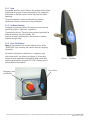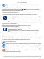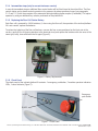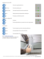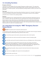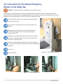
1
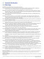
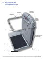
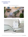
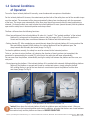
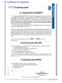
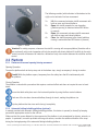
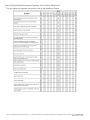
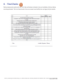
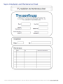
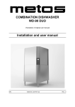
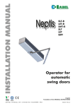
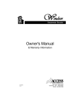
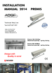
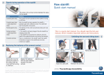
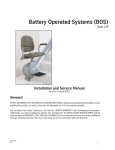
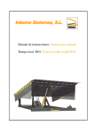
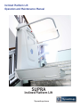
Inclined Platform Lift
Operation and Maintenance Manual
SUPRA
Inclined Platform Lift
ThyssenKrupp Access
Dear Valued Customer,
We congratulate you and thank you for choosing a ThyssenKrupp Access product.
This manual contains the main indications to be followed for a correct use of the
machine you have purchased.
Please read this booklet carefully: it contains simple information, advice and
warnings, all illustrated clearly and briefly.
Please store the manual so it is available to users at all times and contact
ThyssenKrupp Access if you have any questions.
Yours Sincerely,
ThyssenKrupp Access
Contents
1.
1.1
1.2
1.3
1.4
1.5
1.6
1.7
2.
2.1
2.1.1
2.1.2
2.1.3
2.1.4
2.1.5
2.1.6
2.1.7
2.2
2.2.1
2.2.2
2.2.3
2.3
2.3.1
2.3.2
2.3.3
2.3.4
2.4
2.4.1
2.4.2
2.4.3
3.
3.1
3.2
3.3
3.4
3.5
3.6
4.
5.
6.
7.
8.
General Information
Warnings
Illustration of the Inclined Platform Lift
Illustration of the Applications
General Conditions of Operation
Certificate of Compliance
Electrical Connection
Keys and Emergency Tools
Description of the Inclined Platform Lift
Controls
Stop
On Board Controls
Floor Call Stations
Intermediate Stops
Replacing the Floor Call Station Battery
Check Panel
Radio remote control
Platform
Platform with manual opening/closing movement
Automatic folding/unfolding platform (optional)
Lateral Flaps
Options
Folding Seat
Auxiliary Power System
Cover Cloth
Lateral Motorized Ramp (Long side access)
Operation
Stop
Load Control System
Dual tone siren: assistance request device
Safety Functions
Overview
Anti-Impact and Anti-Shearing functions
Flaps
Arresting functions
Instructions for Using the “MME” Emergency
Descent Manual Device
Instructions for the Manual Emergency
Release of the Safety Bar
Maintenance
Faults
Warranty
Approvals
Final Checks
4
4
5
6
7
8
9
9
9
9
10
10
10
12
12
12
13
14
14
14
15
15
15
15
16
16
16
17
17
17
17
17
17
18
19
19
20
21
23
23
23
24
©2011, ThyssenKrupp Access Manufacturing, LLC • 4001 East 138th Street • Grandview, MO 64030 • Phone: 800-825-3100 • Fax: 816-763-4467 • Page 3 of 25
REV A 05.05.11 Supra
1. General Information
1.1 Warnings
CAUTION: read carefully safety and operation instructions.
The inclined platform lift is to be used only by persons who are capable of operating it safely or, otherwise,
under the supervision of another person, duly trained in its safe and proper use.
We strongly recommend not allowing the inclined platform lift to be used by minors and/or those who cannot operate it safely. In this case, the inclined platform lift must be used under the supervision by another person, duly trained in its safe and proper use.
While in use, maintain a correct position according to the inclined platform lift set-up, and always look in the direction of travel.
Once aboard with the wheelchair, you must remain in correct position. not setting the wheels down on the
movable straps and ensuring that you have acquired stability on the platform after operating the two stationing brakes with which the chair is equipped.
Check that nothing can be placed between the inclined platform lift and the guide (in particular, pay attention to clothing, umbrellas or canes).
During travel, especially if the machine is commanded with calls from the floors, the user must pay particular attention that no persons or objects are in the path of the inclined platform lift.
Safety devices are installed to neutralize any dangerous situations: do not create fictitious danger situations to test them, abusing their utilization, and do not tamper with them for any reason. Testing the correct operation of these devices is done solely by the maintenance service.
The maximum capacity of the inclined platform lift is indicated on the serial number tag, bearing the CE
marking; never exceed this value for any reason whatsoever.
The inclined platform lift is designed to carry a single person. In case of improper use (carrying things), ensure that the weight of the load does not exceed the indicated capacity and that the load is positioned correctly and fastened onto the platform.
For the inclined platform lift to work well over time, the machine must be properly maintained. ThyssenKrupp Access recommends establishing a planned maintenance contract with an authorized dealer. The
documents, manuals, and tools for emergency operations supplied with the Journey should be kept in a safe place.
Their location must be known to all those who are authorized to use the inclined platform lift, or appointed to help others use it, safely and in accordance with the provisions of this manual.
If the inclined platform lift is installed in front of railings accessible from the rear, it is necessary to plug the
segments that would allow touching of the rear of the moving inclined platform lift.
The guide of the inclined platform lift is not “intentionally connected to ground”. For applications where the building’s owner deems it necessary to implement protection against the effects of lightning during use, direct contacts need to be made with the manufacturer to define the type of protection required.
The range of ambient temperatures for which the inclined platform lift will operate properly is between 32°F and +113°F; for storage, ambient temperature ranges between 23°F and +131°F are allowed.
DO NOT use the inclined platform lift in the presence of ice formations, including both the guide and the vertical supports, and the inclined platform lift body.
The customer shall provide with an adequate staircase lighting (minimum 50 LUX) and with a light socket to be available to the mechanics for maintenance and inspections requirements.
NOTE FOR US MARKET: Installation is to be made in accordance with the current edition of the U.S. National Electric Code NFPA-70
and the Standard for Platform Lifts and Stairway Chairlift ANSI/ASME A18.1:2005,Section 3 or 6 (whichever is relevant for the
installation location).
NOTE FOR US MARKET: A Listed or Recognized Circuit Breaker with minimum voltage rating of 240Vac and maximum current rating of
16A is requires.
©2011, ThyssenKrupp Access Manufacturing, LLC • 4001 East 138th Street • Grandview, MO 64030 • Phone: 800-825-3100 • Fax: 816-763-4467 • Page 4 of 25
REV A 05.05.11 Supra
1.2 Illustration of the
Inclined Platform Lift
Check panel
Safety bars
Emergency
push button
Handle
Fuse
On board
commands
(joystickey)
Machine body
Anti-impact and antishearing ramps.
Platform with
underneath anticrushing device
Serial number tag
Anti-impact flaps
©2011, ThyssenKrupp Access Manufacturing, LLC • 4001 East 138th Street • Grandview, MO 64030 • Phone: 800-825-3100 • Fax: 816-763-4467 • Page 5 of 25
REV A 05.05.11 Supra
1.3 Illustration of the
Applications
Figure 1 – View of the Inclined Platform Lift
Straight Staircases
Curved Staircases
©2011, ThyssenKrupp Access Manufacturing, LLC • 4001 East 138th Street • Grandview, MO 64030 • Phone: 800-825-3100 • Fax: 816-763-4467 • Page 6 of 25
REV A 05.05.11 Supra
1.4 General Conditions
of Operation
To use the Supra inclined platform lift correctly, some fundamental concepts are listed below:
For the inclined platform lift to move, the containment position both of the safety bars and of the movable straps
must be reached. The movement of the straps automatically takes place simultaneously with the movement
of the bars. The straps open automatically at the floor stops about two seconds after the travel pushbutton is
released. On-board controls are used to make the inclined platform lift move (ascent/descent) with the platform
open and the safety bars in horizontal position and straps raised.
The floor call boxes have the following functions:
- Move (ascent/descent) the inclined platform lift when it is “parked”. The “parked condition” of the inclined platform lift, corresponds to the position shown in the first image of Figs. 2 where the platform is closed and the safety bars are enclosed between the Platform and the machine body.
- Parking function [P]. After completing an ascent/descent aboard the inclined platform lift, having reached the floor and having stepped off the platform, the inclined platform lift has the platform open, the strap lowered and the safety bar raised (image 2 of Fig.2)
To close the platform correctly, the safety bar must be returned to the horizontal position.
To do so, you have to act on the floor call, selecting the direction of travel you have just completed; this
procedure is represented by the symbol [P]; at this point, the safety bar will lower automatically.
You can now close the platform, automatically storing the safety bar between the platform and the case; see
next point.
- Closing/opening the platform. If the inclined platform lift is provided with automatic folding/unfolding platform (optional), the platform is opened and closed by a motorized system, simply acting on the floor call, rotating the key in one of the two directions: one direction opens the platform and the other one closes (image 3 of Fig.2)
1
2
3
4
Figure 2 - Main operations of the Inclined Platform Lift
Caution! Never leave the inclined platform lift with the platform open and the bars raised. After use,
move the bar to the horizontal position and close the platform, ensuring that the bars are closed between
the machine body and the platform and hence in PARKED CONDITION.
©2011, ThyssenKrupp Access Manufacturing, LLC • 4001 East 138th Street • Grandview, MO 64030 • Phone: 800-825-3100 • Fax: 816-763-4467 • Page 7 of 25
REV A 05.05.11 Supra
1.5 Certificate of Compliance
Figure 3 - Certificate of Compliance
©2011, ThyssenKrupp Access Manufacturing, LLC • 4001 East 138th Street • Grandview, MO 64030 • Phone: 800-825-3100 • Fax: 816-763-4467 • Page 8 of 25
REV A 05.05.11 Supra
1.6 Electrical Connection
The electrical connection, upstream of the inclined platform lift, must be performed by authorized personnel, in
accordance with national electrical code.
Power supply voltage shall be 230 V ± 10%, 50 Hz. The current absorbed by the inclined platform lift is as
follows:
Model
Supra
Acceleration
Steady State
13 A
7A
The phase, neutral, and ground conductor must be dimensioned according to the above data and in any case
with no less than 2.5 mm2 cross section.
NOTE FOR US MARKET: Installation is to be made in accordance with the current edition of the U.S. National Electric Code
NFPA-70 and the standard for platform lifts and stairway chairlift ANSI/ASME A18.1:2005, section 3 or 6 (whichever is
relevant for the installation location). A Listed or recognized circuit breaker with minimum voltage rating of 240VAC and
maximum current rating of 16A is requires.
1.7 Keys and Emergency Tools
The user receives, together with the inclined platform lift, the following components:
(2) keys to enable and operate the inclined platform lift both from onboard and from the wall mounted call boxes.
(1) kit of tools to be used solely under emergency conditions.
The emergency tool kits should be placed in a safe place, accessible to authorized personnel. After their use, we
strongly recommend stowing them immediately in their original location, so they will not get lost.
2. Description of the Inclined Platform Lift
2.1 Controls
Note: all the controls of the inclined platform lift are of the “DEAD MAN” type; releasing the controls stops any ongoing movement.
The inclined platform lift can be operated by means of the floor call stations or using the onboard controls.
Every time the inclined platform lift is in operation, follow the inclined platform lift with your eyes and be ready to stop it immediately in case of danger due to collision against any obstacles.
When the movement is commanded from onboard, the safety bars are blocked in horizontal position. When the
floor is reached, only the safety bar corresponding to the floor is raised automatically, the other one remains
locked in horizontal position. In particular cases, and only for arrival to the lower floor, both safety bars can be
raised. In emergency conditions, it is always possible to unlock the bars using the appropriate tools.
©2011, ThyssenKrupp Access Manufacturing, LLC • 4001 East 138th Street • Grandview, MO 64030 • Phone: 800-825-3100 • Fax: 816-763-4467 • Page 9 of 25
REV A 05.05.11 Supra
2.1.1 Stop
All onboard and floor control stations are provided with red stop
pushbutton to be used in case of emergency. The emergency
pushbutton on the floor control station stop only the station
operating.
To resume operation, reset the pushbutton by rotating
clockwise as shown by the arrow on the pushbutton.
2.1.2 On Board Controls
To operate the inclined platform lift simply use one of the two
special keys called “Joystickey” supplied by
ThyssenKrupp Access. These keys are designed specifically to
make the machine very user-friendly. The
direction of travel is determined by the direction of rotation
imparted using the key.
2.1.3 Floor Call Stations
Note: all the controls of the inclined platform lift are of the
“DEAD MAN” type; releasing the controls stops any ongoing
movement.
On the floor call boxes are positioned: 1 emergency stop
push button and 1 key selector (see figure 5); all machine
motion controls imparted are signaled by three consecutive
audible signals and by the green LED (“OK”) flashing on the
control panel of the machine.
Emergency stop
push button
Figure 4 - Joystickey
Key selector
©2011, ThyssenKrupp Access Manufacturing, LLC • 4001 East 138th Street • Grandview, MO 64030 • Phone: 800-825-3100 • Fax: 816-763-4467 • Page 10 of 25
REV A 05.05.11 Supra
Figure 5 - Floor Call Station
Note: The inclined platform lift can be moved along the guide of the floor call boxes, only when the
platform is closed.
Key Selector – Movement of the Inclined Platform Lift
Introduce the key into the three-position selector switch
0
travel and keep it rotated until the inclined platform lift arrives.
, rotate the key in the selected direction of
Key Selector switch – Readying for boarding
With the inclined platform lift present at the floor and platform with manual opening, it is sufficient to:
a) manually open the platform
b) operate the boarding control and wait; raise the safety bar and lower the strap in motorized manner. With the inclined platform lift present at the floor and optional motorized opening of the platform (REM):
a) keep the boarding control activated to allow the motorized opening of the platform, bar and strap.
Key Selector switch – Parking function [P]
Once the use of the inclined platform lift is finished, the machine can be “parked”.
With manually opened platform, it is sufficient:
a) Operate the control [P] until the safety bar is completely lowered.
b) Close the platform manually.
With platform equipped with optional REM:
a) Press and hold the control [P] until the safety bar is completely lowered and the platform closes.
The start and the stop of the inclined platform lift are slightly delayed relative to the operation of the key selector switch, to ensure that the maneuver was intentional.
Red emergency stop pushbutton
When pressed, it stops the motion of the inclined platform lift. If it is activated, the mushroom head pushbutton
remains in a “retracted” position. To deactivate the emergency stop, the pushbutton must be rotated following
the direction of the arrows until the pushbutton is released and moves outwards.
The floor call station contains 2 LEDs:
“Low Battery” LED: the LED lights up to indicate that the battery is low and that it needs to be replaced.
Command execution LED: the LED lights up when a control is activated and it turns off as soon as the control is no longer active; the commands sent by the call boxes are indicated by a flashing light.
Caution! When the “low battery” LED lights up, the floor call should not be used because the operating time left is just a few minutes, so the battery must be changed before use. ThyssenKrupp Access recommends always keeping a spare battery.
©2011, ThyssenKrupp Access Manufacturing, LLC • 4001 East 138th Street • Grandview, MO 64030 • Phone: 800-825-3100 • Fax: 816-763-4467 • Page 11 of 25
REV A 05.05.11 Supra
2.1.4 Intermediate stops (only for curved staircases version)
In case of intermediate stop an additional floor control station will be fitted closed to the wished floor. The floor
control station and on board controls operation is the same as the above mentioned cases (see paragraphs
2.1.2 and 2.1.3) with the exception of the automatic folding/unfolding platform option (if available). This option
operates by using an additional key selector positioned on the platform lift.
2.1.5 Replacing the Floor Call Station Battery
Each floor call is powered by 4 AAA batteries; if, when using the floor call, the operation of the inclined platform
lift is not smooth, replace the batteries.
To replace the batteries of the floor call stations, unscrew the four screws positioned on the front part at the
corners, gently lift the lid (paying attention to the electrical wires) and replace the batteries with new ones of the
same type; lastly, close and screw the lid again (Figure 6).
Figure 6 - Battery Replacement
2.1.6 Check Panel
The check panel of the inclined platform lift contains: 1 emergency pushbutton, 2 machine operation indication
LEDs, 1 sound indicator (Figure 7).
Lt LED
Emergency
push button
Rt LED
Figure 7 - Check Panel
©2011, ThyssenKrupp Access Manufacturing, LLC • 4001 East 138th Street • Grandview, MO 64030 • Phone: 800-825-3100 • Fax: 816-763-4467 • Page 12 of 25
REV A 05.05.11 Supra
Operation of the Left LED
Off
No power supply/replace fuse
Solid Green
Stand-by (awaiting use)
Flashing Green
Command received from wall mounted calls
Yellow
Safety function (anti-impact/anti-crushing) on
Red
Emergency pushbutton pressed
Operation of the Right LED
Off
No alarm
On
Extra-travel/parachute on (contact the service department)
Sound signal
1 beep Travel command received by onboard pushbuttons
2 beep
Inclined platform lift has reached the floor
3 beep
Inclined platform lift is leaving
2.1.7 Radio remote control
The radio control is to be used for platform lift
activation in addition to onboard controls.
Figure 8 - Radio Remote Control
©2011, ThyssenKrupp Access Manufacturing, LLC • 4001 East 138th Street • Grandview, MO 64030 • Phone: 800-825-3100 • Fax: 816-763-4467 • Page 13 of 25
REV A 05.05.11 Supra
The following controls (with indication in illustrations to the
right) can be activated via lever movement:
1–
2–
3–
4–
Lift, this command activates stairlift movement with both an open and closed platform
Open, the stairlift prepares for user boarding
(platform opening is motorised when REM device is present)
Down, this command activates stairlift movement with both an open and closed platform
Close, the stairlift prepares to be closed (platform
closing is motorized when REM device is present)
Figure 9 - Detail
Attention! For safety purposes, whenever the stairlift is moving with an open platform (therefore with a user on board), radio control operation will only be possible with direct platform lift visibility by the radio control user and will however be limited to a distance of only a few meters between the machine and the control.
2.2 Platform
2.2.1 Platform with manual opening/closing movement
Opening Operation
To open the platform both at the top stop and at the bottom stop, simply accompany it during its motion.
Careful! While the platform opens, keep away from the safety bars that lift simultaneously with the platform.
Closing Operation
The platform is closed with a procedure that requires a minimal effort and does not require the user to bend
down:
Ensure that both safety bars are in the horizontal position by using the floor control stations
Push one of the two bars downward halfway through its travel, making the platform rise
Grip the platform that has risen until closing it completely.
2.2.2 Automatic folding/unfolding platform (optional)
In models provided with automatic folding/unfolding platform, this device is opened (or closed) by keeping
pressed the appropriate control on the call box.
Make sure that the space affected by the movement of the platform is not encumbered by objects, animals, or
people. In particular, in models provided with long side access, consider the additional motion of the strap
during the closing/opening of the automatic folding/unfolding platform.
©2011, ThyssenKrupp Access Manufacturing, LLC • 4001 East 138th Street • Grandview, MO 64030 • Phone: 800-825-3100 • Fax: 816-763-4467 • Page 14 of 25
REV A 05.05.11 Supra
The mechanism is sized for operation without extraneous loads and it is provided with
electromechanical protection against overloads; do not contrast the movement of the
platform.
In case of failure or power supply loss, however, the platform can be closed by lifting it manually; this operation
requires a slight pressure to overcome the action of the electromechanical protection device.
2.2.3 Lateral Flaps
The lateral flaps, positioned at the sides of the platform, are an essential element of the inclined platform lift,
and in addition to serving their main function of “JUNCTION WITH THE DEBARKATION PLANE”, serve many
other functions, such as:
Anti-shearing device in the ascending motion (they stop the motion of the inclined platform lift if
something is in the path of the inclined platform lift)
Anti-impact device in the descending motion (they stop the motion of the inclined platform lift if
something is in the path of the inclined platform lift)
Load containment in emergency conditions
Controlling the applied load: if there is an impact or a load is applied on the strap, e.g. one of the
wheelchair’s wheels, a load sensor detects the applied load and if it exceeds the prescribed value, it stops the operation of the inclined platform lift.
To avoid causing the inclined platform lift to stop, the User must pay particular attention:
- not to hamper the motion of the ramps
- avoid leaning on the ramps when the inclined platform lift is in motion, so the safety devices will not be activated
2.3 Options
2.3.1 Folding Seat
The folding seat has a maximum capacity of 265 lbs; never exceed this value.
To open the folding seat, overturn the seat accompanying it to the horizontal position.
Sit on the seat in the correct position, fasten the seat belts (adjusting it, if necessary), hold to the safety bars of
the inclined platform lift and perform the wished travel.
Before closing the Platform, always return the folding seat to the vertical position. In some machines the platform does not move (opening/closing) if the seat is not closed.
2.3.2 Auxiliary Power System
The auxiliary power system is activated every time mains voltage (230 VAC) is lost, and it can power the inclined
platform lift under a full load for a time that depends on the type of device installed, provided the batteries are
charged and fully functional.
We recommend checking the proper operation of the auxiliary power device at least twice a year, removing the
power supply and checking the discharge time of the batteries with the inclined platform lift in operation. If the
operating time is shorter than the figure provided above, the batteries need to be changed.
©2011, ThyssenKrupp Access Manufacturing, LLC • 4001 East 138th Street • Grandview, MO 64030 • Phone: 800-825-3100 • Fax: 816-763-4467 • Page 15 of 25
REV A 05.05.11 Supra
2.3.3 Cover Cloth
It is a cover cloth, specifically designed to best preserve the inclined platform lift as a result of long inoperative
periods and/or when it is installed directly in contact with atmospheric agents such as sun, rain, frost or dust.
2.3.4 Lateral Motorized Ramp (Long side access)
The lateral motorized ramp allows the user to perform boarding/disembarking operations utilizing the long part
of the platform. This side’s profile will also be motorized in the same way the lateral sills are. This chute can
be used whenever boarding/disembarking operation areas are limited or there are obstacles in the way of the
platform lift area.
2.4 Operation
Inclined platform lift parked at the low stop (the platform is closed and the safety bars are housed between the
platform and the machine body).
Open the platform manually, pushing it downwards, paying attention to the bars that rise synchronously with it, until the platform is in the horizontal position. In case of automatic platform: open the platform operating the control key selector switch, paying attention to the bars that rise simultaneously with it, until the platform is in the horizontal position. In case of machine on an intermediate stop, use the key selector positioned on the top cover of the machine, to open/close the platform.
With the platform horizontal, the descent side safety bar rises automatically (this operation also causes the simultaneous lowering of the strap on the platform); climb aboard.
Keep the key rotated until reaching the upper floor. If the lift is at an intermediate stop when the key is
released, the safety bar rises automatically and it is possible to get off from the platform. If the key is not released, the machine continues the travel.
At the upper stop, the inclined platform lift stops automatically. Once the key is released, after two
seconds, the ascent side safety bar rises automatically (this movement will cause the corresponding strap on the exit side to be lowered). In this position, the descent side bar remains horizontal and the corresponding strap remains raised. Remove the key and leave the platform.
Caution! If the platform is closed erroneously without lowering the bar first, you need to reopen the
platform, lower the bar (i.e. moving it to the horizontal position) and close the platform again.
With the inclined platform lift in parked condition (with the platform closed and bars lowered within it), it can be moved by rotating in the desired direction the key of the selectors positioned in the wall mounted call boxes - at the ends of the guide - and keeping it in this position until the desired stop is reached; the control is of the “dead man” type and releasing the key stops the movement of the inclined platform lift.
Insert the key and rotate it in the selected direction; the safety bar will lower automatically and the
inclined platform lift will start to move;
After exiting, to close the platform (high stop), with the wall mounted call box, give the “P” command until the bar is in horizontal position. Then close the platform manually. In case of automatic platform: continue to give the “P” command to close the platform automatically. In case of intermediate stop it is possible to close the platform using the key selector positioned on the top cover of the machine.
©2011, ThyssenKrupp Access Manufacturing, LLC • 4001 East 138th Street • Grandview, MO 64030 • Phone: 800-825-3100 • Fax: 816-763-4467 • Page 16 of 25
REV A 05.05.11 Supra
Caution! In the case of automatic folding/unfolding platform, to avoid hazards and malfunctions, do not force the opening and closing of the safety bars, straps and platform manually. To avoid risk of injury, keep away from arm during operation.
2.4.1 Stop
The onboard and floor control stations are provided with red stop pushbutton to be used in case of emergency.
To restore operation, reset the pushbutton by rotating clockwise as shown by the arrow on the pushbutton.
2.4.2 Load control system
This device detects the load applied on the platform and in case of an overload, stops the stairlift from starting up. Its activation is signalled by an acoustic signal emission; the stairlift does not start up and the LED on the right of the check panel lights up becoming red and the green LED on the left flashes. The acoustic signal relative to this device is recognizable by the fact that it will sound when the machine has come to a halt without any commands given by the User.
2.4.3 Dual tone siren: assistance request device
In the event that the user of the stairlift is in need of assistance, by pushing the emergency button on board, the assistance request device is actuated, which emits a dual tone acoustic signal of 80-90 dBA to attract the attention of assigned personnel.
3. Safety Functions
3.1 Overview
Safety devices are built in compliance with current standards and with utmost accuracy. Nevertheless, said devices must be considered a safety backup and they must not cause any reduction in the considerable attention
that must be paid to any mechanical means.
DO NOT TAMPER with the devices for any reason
DO NOT TRIP the devices without a reason
If you want to verify the proper operation of the devices, YOU ALWAYS MUST ASSURE THE BEST POSSIBLE
SAFETY CONDITIONS, i.e. in such a situation that if the device fails to activate, no dangerous situations will be
caused.
The inclined platform lift is fitted with a master switch to shut off power to the machine.
3.2 Anti-Impact and Anti-Shearing functions
If the inclined platform lift meets an obstacle while ascending/descending, the anti-shearing and anti-impact devices will automatically be activated, stopping travel. At this point, it is possible to resume travel in the opposite
direction. If, once the obstacle is removed, you wish to continue in the same direction, you need to release the
travel control and activate it again.
If during ascending travel with the platform open (with the user onboard), the inclined platform lift meets an obstacle, the anti-shearing safety devices will intervene as follows:
©2011, ThyssenKrupp Access Manufacturing, LLC • 4001 East 138th Street • Grandview, MO 64030 • Phone: 800-825-3100 • Fax: 816-763-4467 • Page 17 of 25
REV A 05.05.11 Supra
a) If the obstacle met is in such a position that it is hit from the ascent side of the platform, when the ascent side
strap, in raised position, comes in contact with the obstacle it will activate a safety device that stops the inclined
platform lift;
b) if the obstacle is in proximity to the guide in such a position that it will be hit by the body of the inclined
platform lift, contact with the sensitive edge positioned on the side of the machine body will activate a safety
device that stops the inclined platform lift.
If, during descending travel with the platform closed (with controls from the calls), the inclined platform lift meets an obstacle, the anti-impact devices intervene; since the platform is closed, the strap covers a part of the body of the inclined platform lift, serving a safety function. The operation is the same as described above.
If during descending travel with the user aboard the inclined platform lift meets an obstacle:
a) If the obstacle met is in such a position that it is hit by the edge of the platform oriented towards the descent
side of the platform, then the descent side strap serves a similar anti-impact safety function to the one
described in the previous paragraph a).
b) If the obstacle is in proximity to the guide in such a position that it will be hit by the body of the inclined
platform lift, then the sensitive edge positioned on the descent side of the case will intervene similarly to the
manner described in the previous paragraph b).
c) if the obstacle is in such a position that it will be hit by the part underlying the platform and the movable
bottom of the platform is hit, then a safety device will be activated, stopping the inclined platform lift.
d) if the obstacle is in such a position that it will be hit by the part underlying the machine body and the movable
bottom of the machine is hit, then a safety device will be activated, stopping the inclined platform lift.
If during descending travel with control from the calls (thus, with the platform closed), the inclined
platform lift meets an obstacle:
a) if the obstacle met is in such a position that it hits the straps, then the safety devices intervene as in the
previous paragraph a)
b) if the obstacle met is in such a position that it hits the machine body, then the safety devices intervene as in
the previous paragraph b)
c) if the obstacle is in such a position that it will hit the inclined platform lift as per the previous point, paragraph
d): the safety devices will intervene as described in that point.
3.3 Flaps
In addition to serving the anti-impact function, the straps also serve to control the load applied on them. A user
on a wheelchair has to position him/herself on the platform correctly, thus without loading the straps. Caution
must be exercised to prevent the “load control system” from operating and blocking the inclined platform lift
without an actual danger.
©2011, ThyssenKrupp Access Manufacturing, LLC • 4001 East 138th Street • Grandview, MO 64030 • Phone: 800-825-3100 • Fax: 816-763-4467 • Page 18 of 25
REV A 05.05.11 Supra
3.4 Arresting Functions
Emergency Pushbutton
The travel of the inclined platform lift can be stopped if dangerous conditions require it. This stop can be
effected by pressing the red mushroom head pushbutton both on board the inclined platform lift and on the
floor call boxes. To resume operation, reset the pushbutton by rotating clockwise as shown by the arrow on the
pushbutton.
Over-travel
If the inclined platform lift fails to stop at the position of the high or low stop, the “extra travel” safety function
will intervene immediately, blocking the inclined platform lift and making it necessary to have competent
personnel work on it to return it to its operating condition.
Parachute
If the inclined platform lift has a mechanical failure that increases descending travel speed beyond a pre-set
limit, a “parachute” brake will be activated directly by a speed limiter and it will stop the inclined platform lift.
After the activation of this safety feature, the inclined platform lift will remain mechanically and electrically
blocked. If there is a failure in the speed limiter, which would compromise its proper operation, the inclined
platform lift stops and remains electrically blocked. In these cases, resuming operation requires having a trained
technician work on it to return it to its operating condition.
3.5 Instructions for Using the “MME” Emergency Descent
Manual Device
Caution! This operation must be executed by skilled personnel.
In case of failure or power supply outage, the inclined platform lift can be made to descend using the dedicated
rod with hand wheel (we recommend positioning it near the master switch).
First, shut off main power to the machine, placing the master switch on the 0 position.
Remove the white cap on the front case with the inscription to uncover the underlying hole.
Insert the Allen wrench end of the rod into the hole on the case, until finding the axis of the bevel pinion.
Press the hand wheel to engage the bevel pinion on the motor, then rotate it in the direction
corresponding to descending travel, i.e. clockwise for left-hand inclined platform lift and counter
clockwise for right-hand inclined platform lift; as an additional safety feature, the engagement of the bevel pinion will shut off power to the auxiliary circuit of the inclined platform lift.
After completing the operation, always remove the hand wheel from the hole before powering the
machine.
The hand wheel must never be left inserted in the inclined platform lift.
Put back the white cap on the hole.
©2011, ThyssenKrupp Access Manufacturing, LLC • 4001 East 138th Street • Grandview, MO 64030 • Phone: 800-825-3100 • Fax: 816-763-4467 • Page 19 of 25
REV A 05.05.11 Supra
3.6 Instructions for the Manual Emergency
Release of the Safety Bar
Caution! This operation must be completed by a trained technician.
If the safety bars remain locked in the horizontal position (after reaching the stops, or because the inclined
platform lift has had a generic failure during travel with the user aboard), only the ascent side safety bar can be
released; the descent side safety bar MUST NEVER be unlocked manually.
First, shut off main power to the machine, placing the master
switch on the 0 position.
Place yourself on the upper step as close as possible to the
platform.
Remove the screw that joints the two machine body cases
(in the bottom of the upside). Using the proper phillips
screwdriver Ø 2,2 PZ.
Enlarge the case and introduce the screwdriver until touching
the bars fork. The finger shown on the pictures indicates the
point where to apply the force.
Push the fork and operate the safety bar. Once the operations
are carried out, take-down the safety bar (it returns automatically
in position).
Fix the screw.
Close the platform.
Figure 10 - Close up view of screw
Figure 11 - Unlocking sequence
©2011, ThyssenKrupp Access Manufacturing, LLC • 4001 East 138th Street • Grandview, MO 64030 • Phone: 800-825-3100 • Fax: 816-763-4467 • Page 20 of 25
REV A 05.05.11 Supra
4. Maintenance
The Journey inclined platform lift requires simple maintenance operations:
Before any maintenance activity on the inclined platform lift, always shut off power to the machine using the master switch.
Keep the sliding guide clean, periodically greasing the track (use small quantities of multipurpose
mineral grease);
Since the guide is made of anodized Aluminum, we recommend using rags dampened with water and to rub with a soft cloth for complete drying.
The case (outer covers of the inclined platform lift, made of plastic) can be washed with water and
neutral detergent. Never use chemical solvents as these could damage the material.
The rubber-coated loading ramp can be washed with common detergents for rubber; the aluminum loading ramp can be washed with normal household detergents.
The inclined platform lift is powered electrically through a cable-holder chain in a “particular
compartment” obtained in the guide; check that there are no obstructions in the chain sliding duct and, if necessary, clean it.
Check the operating condition of the rescue unit (if installed);
To perform maintenance on the inclined platform lift appoint a specialized company that fulfills the
technical and professional requirements set out by current rules and laws.
©2011, ThyssenKrupp Access Manufacturing, LLC • 4001 East 138th Street • Grandview, MO 64030 • Phone: 800-825-3100 • Fax: 816-763-4467 • Page 21 of 25
REV A 05.05.11 Supra
Table of Recommended Maintenance Operations for the Inclined Platform Lift *
* For any matters not expressly set out here, refer to the Installation Manual
©2011, ThyssenKrupp Access Manufacturing, LLC • 4001 East 138th Street • Grandview, MO 64030 • Phone: 800-825-3100 • Fax: 816-763-4467 • Page 22 of 25
REV A 05.05.11 Supra
5. Faults
If the inclined platform lift does not work, perform the following checks before calling the maintenance service.
Is the master switch (circuit breaker) of the machine in the ON position?
Does the inclined platform lift appear to be powered? (See whether the green voltage indicator light on the
check panel is lighted).
Are all safety devices of the inclined platform lift activated? (Stop pushbuttons not engaged, overturning
protections lowered, movable straps free of obstacles and not deformed or loaded.)
Do the check panel indicator lights regularly light up when the checked components are operated?
Providing the maintenance service with this information makes it easier to identify the fault and speeds up
repairs. Tell the maintenance technician the serial number, model, and year of manufacture of the inclined
platform lift.
6. Warranty
THYSSENKRUPP ACCESS inclined platform lifts are guaranteed for twelve months from the date of delivery,
shipment, or installation.
THYSSENKRUPP ACCESS undertakes to repair or replace, at its discretion, free of charge, any parts it may
recognize as defective in terms of design, material or construction.
The warranty does not cover any defects due to the natural wear of the material, batteries and accumulators
and in general all malfunctions due to causes other than the product itself (e.g., lacking or insufficient power
supply voltage, open switches, blown fuses, overload, erroneous operation, etc.).
The warranty does not cover any failures due to an improper use of the machine and neglect by the user, or to
external factors (e.g., damage caused by lack of maintenance or poor maintenance, dirt, floods, fires, etc.). The
warranty is voided if the machine is tampered with, modified, or repaired by persons not authorized by
THYSSENKRUPP ACCESS.
7. Approvals
Under particular environmental conditions, it may become necessary to design particular solutions both for the
inclined platform lift itself and for its operating cycle.
In these cases, a specific design is shared with the Customer/Building owner.
The shared details are provided in this chapter for the sake of completeness, and they contribute to complete
the operating instructions and they are an integral part of this manual and of the delivered inclined platform lift.
©2011, ThyssenKrupp Access Manufacturing, LLC • 4001 East 138th Street • Grandview, MO 64030 • Phone: 800-825-3100 • Fax: 816-763-4467 • Page 23 of 25
REV A 05.05.11 Supra
8. Final Checks
Before releasing the machine for use, all of the verifications indicated in the end installation list found below
must be performed. The list of tests found in the user manual must be filled out and signed by the installer.
©2011, ThyssenKrupp Access Manufacturing, LLC • 4001 East 138th Street • Grandview, MO 64030 • Phone: 800-825-3100 • Fax: 816-763-4467 • Page 24 of 25
REV A 05.05.11 Supra
Supra Installation and Maintenance Sheet
©2011, ThyssenKrupp Access Manufacturing, LLC • 4001 East 138th Street • Grandview, MO 64030 • Phone: 800-825-3100 • Fax: 816-763-4467 • Page 25 of 25
REV A 05.05.11 Supra