1
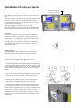
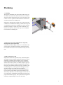
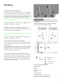
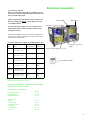
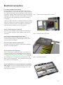
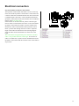
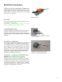
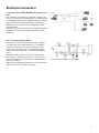
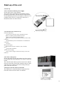
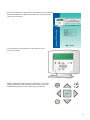
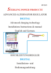
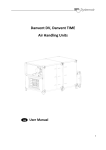
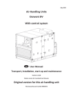
Installation Instructions
Valid from 5. May 2009 - Version 5
Indoor version
Table of contents
Declaration of conformity
3
1. Transport
1.1 Accessories
1.2 Unloading by fork-lift
1.3 Unloading by crane
1.4 Pre-assembly storage
4
4
4
4
4
2. Installaton of units and ducts
2.1 Floor
2.2 Adjustable feet
2.3 Assembling the AHU sections
2.4 Fitting the ductwork
2.5 Free entrance for maintenance
2.6 Dismantling and disposal
5
5
5
5
6
6
6
3. Plumbing
3.1 Free acces
3.2 Pipe connection to coils
3.3 Valve motor and valve for heating
3.4 Valve motor and valve for cooling
3.5 Draining of condensate water
7
7
7
8
10
10
4. Elecrtrical connection
4.1 Quick guide for installaton
4.2 Start-up of the unit
11
12
18
5. Commissioning
20
2
3
Transport
1. Transport
The AHU is delivered in 3 or 4 sections, which are to be assembled on site. The AHU can be lifted by fork-lift or by crane
using suitable lifting straps.
1.1 Accessories
Accessories such as adjustable feet, Disc-Lock, water trap for
condensate water from plate heat exchanger and cooling coil,
spare filters (to be ordered separately) and other loose items,
are packed into a box and put inside the AHU. On the outside
of the unit section, in which these items are placed, will be a
red sticker. Duct connection parts are also placed inside the
AHU (with exceptions). Remember to remove transport fixing
pieces. These are identified by red stickers.
1.2 Unloading by fork-lift
The forks must be long to avoid damage of the underside of
the AHU.
1.3 Unloading by crane
The straps must be secured to the supporting legs as shown in
the illustration. Avoid that the straps press and cause deformation to the top of the unit. Keep the straps on sufficient distance from the unit - use bars or similar - see the illustration
1.4 Pre-assembly storage
The AHU must be protected from weather and impact. The
protective plastic film wrapped around the unit must be removed on arrival on the site and the unit covered with tarpaulin or similar material. In order to minimise condensation, sufficient air circulation must be ensured between the covering
and the unit.
Avoid that the straps press and cause deformation to the top
of the unit. Keep the straps on sufficient distance from the
unit - use bars or similar
4
Installation of units and ducts
Minimum distance to
the ceiling - 700 mm
2. Installation mechanical
NB! When positioning the unit on the site, it must be ensured
that:
The necessary space requirements for service and inspection in
front of the unit are met. It is recommended that a distance
corresponding to the unit s width is kept free for service and
inspection in front of the unit.
The necessary space requirements for access to the
switchboard over the unit are met. It is recommended that the
distance between switchboard and ceiling is at least 700 mm
2.1 Floor
The floor must be level and even for the unit. The building
construction and floor must be able to resist the load of the
AHU. In the case of lightweight construction that might transmit noise and vibrations, tor especially sensitive areas, the unit
must be placed on an absorbing foundation. The adjustable
feet, delivered with the unit, must be replaced by vibration
absorbing material.
2.2 Install the adjustable feet before the sections are
pushed together
The adjustable feet must be fitted in the supporting legs to
level the sections before the sections are pushed together.
2.3 Assembling the AHU sections
Sections are kept together with the Disc-Lock system.
1. Ensure that the factory fitted rubber sealings are undamaged
2. The sections are then to be positioned directly opposite each
other. The feet must be adjusted to get the profiles parallel and
to get the pairs of locking pins for the Disc-Locks at the same
height.
3. The sections must then be pushed together so that the rubber
profiles fit directly into one another (please see the illustration).
Press the sections carefully together to ensure that the DiscLocks will not be used for pulling the sections together.
4. The sections are then to be locked together using the DiscLock system. Place a Disc-Lock on each pair of locking pins.
Each section is prepared for a Disc-Lock at the vertical part of
every corner usually 4 Disc-Locks between 2 sections.
Tighten the Disc-Locks loosely with the supplied tool, until
the sections are pressed hard against each other (please see the
illustration).
5
Installation of units and ducts
2.4 Fitting the ductwork
Flexible connections should always be installed between AHU
and ductwork . It is important that dimensions of ducts and
dimensions of the openings in the unit are strictly identical.
Extract
Exhaust
Supply
Outdoor air
Extract
Outdoor air
Supply
Exhaust
2.5 Free entrance for maintenance
It must be ensured that ducts etc. do not obstruct the inspection
doors and components that can be extracted from the unit. In
special circumstances, where it is impossible to open the inspection doors, the hinge pins can be removed to remove the
doors.
2.6 Dismantling and disposal
Remember to disconnect all electrical and plumbing connections before dismantling. All fluids must be drained and emptied from the unit which must then be disposed of in accordance with the valid and current local regulations. After dismantling of the unit, the sections must be taken apart and the
pieces placed into groups according to the material type. The
materials must then be delivered to an approved site.
6
Plumbing
3 . Plumbing
The pipes on the heating coil for hot water and cooling coil
for chilled water have external thread. If the unit is ordered
with valve motors and control valves, the valve motors and
control valves are packed in cardboard boxes and the boxes
are placed inside the air handling unit
If the unit is ordered with a cooling coil, a water trap for the
condensate is included in the delivery, and the water trap is in
a cardboard box inside the air handling unit. If the unit has a
plate heat exchanger, a water trap for the condensate is included in the delivery, and the water trap is in a cardboard
box inside the air handling unit.
3.1 Free access to extract components for inspection,
cleaning and repair/replacement
It must be ensured that pipes, cables etc. do not obstruct the
inspection doors and that fans and heat exchanger that can
be extracted from the unit can be withdrawn freely from the
unit.
3.2 Pipe connection to coils
Pipes for hot water must be protected by insulation against
frost and loss of heat. Further protection against frost can be
obtained by installing electrical heating wires around the
pipes and under the insulation combined with temperature
sensors and a control system. Circulation pumps in pipe systems are able to improve sufficient supply of hot water protecting the pipes further against frost (pipes, insulation, electrical heating wires, control system for heating wires and
circulation pump are not delivered by Systemair).
Pipes for cooling must be protected by insulation against
loss of cooling in the summer (pipes and insulation is not
delivered by Systemair). The coil and pipes from the coil are
not constructed to withstand the weight and stress from long
pipes and insulation of pipes. The system must be supported
carefully in rigid bearings to roof, floor and walls.
7
Plumbing
3.2.1 Pipe connection to heating coil
The heating capacity of the coil with only 2 rows is independent
of the connection of the hot water in equal flow or in counter
flow to the direction of the air. The pipes on the heating coil are
marked for inlet at the bottom and outlet at the top and this is OK
for air flow from the left side as well as from the right side.
NB! If Glycol is added, the Glycol must be without additives and
auto glycol must not be used.
Automatic bleeding have to be installed at the highest point of
the 2 pipes
supply- or return pipe.
Automatic bleeding
Always important to install automatic bleeding at
the highest point over the heating coil and over the
cooling coil.
Notice that all pipes and the automatic bleeding
devices have to be insulated carefully.
3.2.2 Pipe connection to cooling coil for chilled water
Coils with 3 rows or more must always be connected in counter
flow to the airflow (see the illustration).
NB! The Glycol must be without additives and auto glycol must
not be used.
Automatic bleeding have to be installed at the highest point of
the 2 pipes
supply- or return pipe.
3.3 Valve motor and control valve for heating
If valve motor and control valve were ordered they are packed
in a box and they are not installed. 2- or 3-way valve is delivered as requested.
The coil and pipes from the coil are not constructed to withstand
the weight and stress from circulation pump, valves and thermometers. The system must be supported carefully in rigid
bearings to the floor and to the walls
3.3.1 Valve motor and 2-way control valve for heating
The illustration system with 2-way control valve shows an
example of a system that is working well together with the controller, and the system offers good protection against frost, too
(pump, stop valves, non return valve, thermometers and pipes
are not delivered by Systemair).
2-way control valve for heating.
Secondary circuit
Primary circuit
Pump
Thermometer
Maximum flow valve
Stop valve
2-way control valve
Non return valve
Variable water flow in the primary circuit.
Constant water flow in the secondary circuit.
The preferred system for district heating.
8
Plumbing
3.3.2 Frese Optima 2-way control valve for heating
Intelligent 2-way control valve that adjusts itself automatically to
avoid exceeding the preset maximum flow. Even by fluctuating
pressure in the system, the maximum flow is not exceeded for
differential pressure up to 400 kPa. In practical terms, the OPTIMA valve ensures that there are no overflows and that the
valve has total control authority in the primary circuit The valve
is always delivered with the special actuator for without other
differential pressure valves. the long valve stroke. Protection
class IP44. Short-circuit-proof and protected against polarity reversal. Flushing the valve is possible due to the removable cartridge. No minimum straight pipe lengths required before or after
the valve.
The system is working well together with the controller, and the
system offers good protection against frost, too (pump, stop
valves, non return valve, thermometers and pipes are not delivered by Systemair).
2-way control and maximum flow valve from Frese for
heating.
Secondary circuit
Primary circuit
Pump
Thermometer
Stop valve
Maximum flow valve
2-way control valve with maximum flow setting
Non return valve
Variable water flow in the primary circuit.
Constant water flow in the secondary circuit.
The preferred system for district heating.
_______________________________________________
3.3.3 Valve motor and 3-way control valve for heating
The illustration system with 3-way control valve and constant
flow in the primary circuit shows an example of a system that is
working well together with the controller, and the system offers
good protection against frost, too (pump, stop valves, non return
valve, thermometers and pipes are not included in the delivery
from Systemair).
System with 3-way control valve for heating.
Secondary circuit
Primary circuit
Pump
Thermometer
Maximum flow valve
Stop valve
3-way control valve
Non return valve
Constant water flow in the primary circuit.
Constant water flow in the secondary circuit.
9
Plumbing
3.4 Valve motor and control valve for cooling
If valve motor and control valve were ordered, they are packed
in a box and they are not installed. 2- or 3-way valve is delivered
as requested.
The coil and pipes from the coil are not constructed to withstand
the weight and stress from circulation pump, valves and thermometers. The system must be supported carefully in rigid
bearngs to the floor and to the walls
3.4.1 Valve motor and 3-way control valve for cooling
The illustration system with 3-way control valve and constant
flow in the primary circuit shows an example of a system that
is working well together with the controller (pump, stop valves,
non return valve, thermometers and pipes are not delivered by
Systemair).
3.5 Draining of condensate water
Drip trays to collect condensate water are installed under plate
heat exchanger and cooling coil. Each drip tray is provided with
a drainage outlet. To avoid freeze ups and frost bursts of pipes,
sufficient insulation is recommended and installation of heating
between the pipes and the insulation could even be necessary
(insulation and heating is not included).
3.5.1 Draining from plate heat exchanger
The drip tray under the plate heat exchanger works under negative air pressure. To ensure that the water escapes from the tray
under the plate heat exchanger, a water trap is included in the
delivery, but not installed.
To ensure the safe draining of water, the closing level of the
water trap must be estimated correctly (see the illustration and
estimate the minimum closing level according to the table).
3-way control valve for cooling with chilled
water.
Secondary circuit
Primary circuit
Thermometer
Maximum flow valve
Stop valve
3-way control valve
Constant water flow in the primary circuit
Variable water flow in the secondary circuit
_______________________________________________
Negative pressure P (Pa)
P
H1 Min.
H2
500 Pa
100 mm
40 mm
750 Pa
150 mm
55 mm
1000 Pa 190 mm 70 mm
3.5.2 Draining from cooling coil
The drip tray under the cooling coil works under positive air
pressure, and a water trap for the draining is included but not
installed.
The cooling coil is installed after the fan, and to prevent air
from flowing out or into the sewage system, the closing level of
the water trap must be correctly estimated (see the illustration
and estimate the minimum closing level according to the table).
Positive pressure P (Pa)
P
H1 Min.
500 Pa
90 mm
750 Pa
120 mm
H2
65 mm
90 mm
1000 Pa 150 mm 120 mm
10
4. Electrical connection
Do not start the Danvent TIME Air Handling Unit until all electrical and mechanical safety precautions have
been read and understood.
Check carefully that this manual really is used for the
Danvent TIME the indoor version and not for Danvent TIME Outdoor.
Electrical connection
Switchboard
Main switch
Frequency converter - exhaust
Note that the mains supply has to be connected by an
authorized installer and in accordance with current
wiring instructions.
The Danvent TIME as well as the electrical equipment is
exclusively for indoor installation and must be protected
against water and humidity.
Necessary mains power supply for TIME Outdoor units
AHU:
Motor:
Fuse (minimum):
Fuse (max):
TIME 10
2 x (1,1 kW - 2,6 A)
16 A
16 A
16 A
16 A
16 A
16 A
Frequency converter
supply
Rotation speed regulation rotor
2 x (1,5 kW - 3,3 A)
TIME 15
2 x (1,5 kW - 3,3 A)
2 x (2,2 kW - 4,4 A)
TIME 20
2 x (2,2 kW - 4,4 A)
Hand terminal
2 x (3,0 kW - 6,6 A)
TIME 25
TIME 30
2 x (3,0 kW - 6,6 A)
16 A
16 A
2 x (4,0 kW - 8,5 A)
25 A
32 A
2 x (4,0 kW - 8,5 A)
25 A
32 A
2 x (5,5 kW - 11,4 A)
25 A
32 A
2 x (7,5 kW - 15,2 A)
35 A
50 A
2 x (5,5 kW - 11,4 A)
TIME 40
The unit must be permanently connected to the mains supply
through the lockable safety switch.
Find the circuit diagrams, cable plans, part lists and terminal plans in a separate booklet
Content of this separate booklet;
General description
Circuit diagram
Switchboard layout
pages
1- 9
10 - 24
25 - 29
Graphical list
Cables
Cables-cores
Terminal matrix
Cable plan
Terminal plan
Part list
30 - 39
40 - 49
50 - 59
60 - 69
70 - 79
80 - 89
11
Electrical connection
4.1 Quick guide for the installation.
Before shipment the unit has been assembled and has passed a
final functional test. A copy of the test report is delivered with the
unit. After the final test the unit is divided into separate sections to
facilitate the transport. When the unit has been reassembled on the Step 1 - Cables in winches prepared for connection
building site, the cables between the sections must be reconnected
to the terminals in the switchboard. The cables are marked for
reconnection.
Cables to external components are included in the delivery and the
cables are connected to all external components. All external components with connected cables are packed into a cardboard box placed besides the switchboard on the top of the unit.
Step 1: Cables prepared for connection.
The cables to be connected to the terminals in the switchboard
are very visible in the small winches. Make the cables free for
connection.
Step 2 - Pull back cables to the board
Step 2: Pull the cables through the cable entries
Pull the cables through the rubber seal in the roof panel, behind the switchboard. Pull the cables through the cable entries
on the back of the switchboard
Step 3: Install the cables in terminal blocks
All cables are marked with numbers. Install cables in terminals
with the corresponding numbers.
Step 4: Install external components
These are the supply air temperature sensor, valve motor(s) (if
requested), control valve(s) (if requested), sensor for water temperature in the heating coil (if water heating coil was requested),
circulation pump (if water heating coil in the system), 2 air pressure transmitters if it is a solution for constant pressure in the
ducts, a repeater (if requested) - see the information below under
step 9 about external components.
Step 3 - Reinstall in the board
Step 5: Install cables from external components and cable for
mains supply. It must be ensured that cables do not obstruct the
inspection doors and that fans and heat exchanger can be withdrawn freely from the unit.
12
Electrical connection
Step 6: Install the Systemair Control Panel.
The Systemair Control Panel with cable is in a box on the top
of the unit and the Systemair Control Panel is connected to the
controller inside the switchboard because the cable with socket
is pulled through a cable entry in the switchboard. Mount the
Systemair Control Panel on the wall and take into consideration
that the cable is 10 metres long.
If the installer on the final site must pull the cable through a
narrow whole in a wall because the unit is in one room and the
Systemair Control Panel in another room, the installer must
demount the cable on the backside of the Systemair Control
Panel - pull the cable through the narrow whole - adjust the
length of the cable and remount the cable (Wiring diagram
about the cable colours and terminals are show here to the
right).
The control Panel is supplied with power from the controller,
and it is not possible make this cable longer. If 10 metres of
cable is not sufficient, a repeater must be installed between the
Systemair Control Panel and the controller. This is described in
step 8 below.
13
Electrical connection
Step 7: Pressure transmitters over the fans for control
in m3/h.
If the air handling unit was ordered for control in m3/h
through the supply fan and the exhaust fan, the pressure
transmitters are installed inside the unit by the factory. The
system has been tested, - no installation to do - this is ready
for start-up.
Step 7 - pressure transmitters in the ducts
or
Pressure transmitters in the ducts for control of duct
pressure in Pa.
If the air handling unit was ordered for control in Pa of pressure in the ducts, the air volume from the air handling unit
must be adapted continuously to maintain the set point pressure in the ducts. With control of pressure in ducts, there are
no pressure transmitters installed inside the unit over the
fans, but the pressure transmitters must be installed in the
main ducts one pressure transmitter in the main duct for the
supply air and one pressure transmitter in the main duct for
the exhaust air. The pressure transmitters are packed in a box
placed beside the switchboard on the top of the unit. The
pressure transmitters are connected in the switchboard.
Pressure transmitter
installed on duct
Exhaust: Install the
hose on minus for negative pressure
Supply: Install the hose
on plus for posivtive
pressure
It is important to select positions for the pressure transmitters without heavy turbulences in the ducts, because stable
signals to the controller are very important.
Step 8 - Installation of supply air sensor
Step 8: Installation of supply air temperature sensor
The supply air temperature sensor is packed in a box placed
inside the unit. Drill a hole in the supply air duct at least 1
2 metres away from the heating or cooling battery and mount
the sensor.
14
Electrical connection
Step 9 Details about electrical connection of external components
Repeater
If the distance between controller and control panel is
more than the 10 metres of cable from the control panel
allows, the repeater EO-R is necessary. Simple extension of the cable without the repeater will lead to malfunction and severe problems. Up to 1200 m cable
length between the controller and the repeater is possible. The distance between the repeater and the control
panel is restricted to the 10 metres of cable from the
control panel. Supply voltage for the repeater is 24 V
AC from the switchboard and protection class is IP20.
One control panel is able to control up to six air handling units through one repeater with an E28 controller
in each air handling unit.
Repeater type EO-R
Extended operation (Push button)
When the unit is running at reduced speed or is in shutdown mode, it can be forced up one step by using a
Push button (impulse). Chose the required number of
minutes for The Extended operation in the control
panel. Button and cable are not delivered from Systemair
Actuator on valve for heating battery (hot water)
Supply voltage for the water valve actuator is 24V AC,
control signal is 0-10 V DC, and for frost protection a
sensor for water temperature has to be installed in the
heating coil. Cables from the controller to valve motor
and water temperature sensor is delivered by Systemair.
The standard valves are available for 2 or 3-way connecBelimo actuator
tion. Valves from Frese are only available for 2-way
connection ( the valve from Frese are intelligent control
valves with integrated differential pressure control that
adjust itself automatically to avoid exceeding preset
maximum flow).
For frost protection
a water temperature
sensor has to be
installed between
supply and return
pipes
Valve from
Frese with
actuator
15
Electrical connection
Actuator on valve for cooling battery (chilled water)
Supply voltage for the water valve actuator is 24V AC,
control signal is 0-10 V DC. Cable between valve motor
and controller is included. Standard valves are available
for 2 or 3-way connection.
Belimo actuator
DX cooling
A DX-cooler can be connected to the controller. Input
and output are available for:
Start cooling Alarm cooling Cooling Y3. No cable
and flow sensor are delivered by Systemair
Circulation pump heating
Circulation pump is not included in the delivery from
Systemair. If the pump has not been activated for 24
hours, the pump is exercised once daily for 1 minute to
keep the pump in a good condition. Cable for the pump is
included
Fire function
Thermostats
Everything is installed and configured for start-up, if the
unit is ordered with two thermostats. The thermostats
are installed in the unit one in the extract air and one
in the supply air. The cut off temperature in the thermostats is adjustable. At the factory, supply is set at 70 C
and extract is set at 40 C. The controller is as standard
configured to stop the fans and close the dampers if a
thermostat is released. Skilled technicians are able to
change the configuration on the site.
Circulation pump - not included in the delivery from Systemair
Thermostat for activation of fire
function - adjustable temperature
Fire function
prepared for activation by smoke
detectors or external fire detection systems
Smoke detectors or similar are not supplied by
Systemair. At the factory the controller is as standard
configured for the contact in the activation device to be
normally closed when no fire is detected. When the activation device is activated - contact is open - the fans
stop and the dampers close. Skilled technicians are able
to change the configuration on the site.
16
Electrical connection
Communication to BMS (Building Management System)
The controller is available in 3 different versions. One
version is prepared for communication to a BMS system
via MODBUS and EXO 4 via RS485, another version is
prepared for EXO4 communication by TCP/IP and
WEB interface, a third version is prepared for LON
communication.
Special set-up of the controller for communication with
the BMS system is not included in the delivery from
Systemair.
E Tool (commissioning software)
PC software called E tool for fast and easy configuration and supervision of the functions via a graphical
interface is available. This software displays all the
parameters to be written in a commissioning report see the separate instructions - Operation and Maintenance.
Download of this software is free for installers from
www.regin.se. Terminals 50-52 (B, A, N) on the Corrigo E28 controller are prepared for communication to
the E tool software.
N.B. For more detailed information see the instructions
attached to the E Tool software program.
Screen picture from the E Tool (example)
17
Start-up of the unit
4.2 Start-up
4.2.1 Connection of mains power supply
See the page in the circuit diagram.
The power supply installation in the building must be
provided in accordance with the statutory requirements
for the additional protection of frequency converters. If a
residual current device is connected, it must have a
threshold current of at least 300 mA.
4.2.2 Checklist before initial start-up
External components
Are the valve and valve motor installed correctly?
Is the circulation pump installed correctly?
Water in the coil and circulation pump?
If this is a system with pressure transmitters in the ducts,
it must be
checked that the pressure transmitters are installed and
connected
correctly?
Main power supply
Connected correctly? (3x400 V, Zero, Ground)
Ducts
Are all ducts installed?
Test of control voltage
Is the control voltage connected correctly to the valve
motor(s)?
4.2.3 Turn on the power
Do not start until all safety procedures have been carried
out carefully and ensure that doors are always closed and
locked.
The controller and control system are now active and the
unit may start if the clock in the controller starts at a time
where the unit according to the time setting in the program orders the unit to run.
4.2.4 Insert relevant values in controller
The TIME unit is controlled from the Systemair Control Panel. Insert relevant values in controller.
18
See the User manual for Danvent DV and TIME units. You will find
detailed information and illustrations about how to insert relevant
values in the controller
Use the buttons on the Systemair Control Panel to insert
the relevant values.
Buttons and lamps on the Systemair Control Panel. Text on the
display combined with description and illustration in the User
manual should guide you successfully to start of the unit.
19
The short advise is to adjust the time in the internal clock
weekday) in the User manual.
If the unit does not start now, you should go to
On.
see the Calendar settings (time, date,
Running mode and change the setting to
If Alarms do not occur now, the unit should start and run.
Further information is available in the Operation and Maintenance instructions in case of alarm and malfunction.
Changes of the most common settings and parameters are described in the Operation and Maintenance instructions
5. Commissioning
When the installation is finished, check that:
There is no unusual noise from the unit
Control panel and lamp signals are OK?
Dampers are working as required?
Valves are working as required?
Recovery - On or off as required?
Sound attenuators are installed and the duct
system is connected correctly to the unit
Outdoor air intake is positioned with sufficient distance to pollution sources (kitchen ventilator exhaust, central vacuum system exhaust or similar)
The unit has been installed in accordance with these instructions
Commissioning Report - A Commissioning Record with data according to the requests of the customer, and the signature of the installer will prove that the installation job has been completed and the
unit is ready to be paid for by the customer.
A copy of the Commissioning Report printed on paper is in the Operation and maintenance instructions for the TIME unit
The Commissioning report is also available as a Word file
office.
please ask for this on the Systemair sales
20