1
DAQ
Traditional NI-DAQ (Legacy) User Manual
TM
Version 7.x
Data Acquisition Software for the PC
Traditional NI-DAQ (Legacy) User Manual
Traditional NI-DAQ (Legacy) is an older driver with outdated application
programming interfaces (APIs) for developing data acquisition, instrumentation, and
control applications for older National Instruments DAQ devices. You should use
Traditional NI-DAQ (Legacy) only in certain circumstances. Refer to the NI-DAQ
Readme for more information about when to use Traditional NI-DAQ (Legacy),
including a complete list of supported devices, operating systems, application
software versions, and language versions. Refer to the NI-DAQmx Help, which you
can access from Start»Programs»National Instruments»NI-DAQ»
NI-DAQmx Help, for an overview of the two NI-DAQ APIs and the advantages of
NI-DAQmx. In NI application software, this same help is available by searching for
NI-DAQmx. You can install the latest version of NI-DAQmx software, available at
ni.com/downloads.
Caution
Traditional NI-DAQ (Legacy) User Manual
August 2005
370696B-01
Support
Worldwide Technical Support and Product Information
ni.com
National Instruments Corporate Headquarters
11500 North Mopac Expressway
Austin, Texas 78759-3504
USA Tel: 512 683 0100
Worldwide Offices
Australia 1800 300 800, Austria 43 0 662 45 79 90 0, Belgium 32 0 2 757 00 20, Brazil 55 11 3262 3599,
Canada 800 433 3488, China 86 21 6555 7838, Czech Republic 420 224 235 774, Denmark 45 45 76 26 00,
Finland 385 0 9 725 725 11, France 33 0 1 48 14 24 24, Germany 49 0 89 741 31 30, India 91 80 51190000,
Israel 972 0 3 6393737, Italy 39 02 413091, Japan 81 3 5472 2970, Korea 82 02 3451 3400,
Lebanon 961 0 1 33 28 28, Malaysia 1800 887710, Mexico 01 800 010 0793, Netherlands 31 0 348 433 466,
New Zealand 0800 553 322, Norway 47 0 66 90 76 60, Poland 48 22 3390150, Portugal 351 210 311 210,
Russia 7 095 783 68 51, Singapore 1800 226 5886, Slovenia 386 3 425 4200, South Africa 27 0 11 805 8197,
Spain 34 91 640 0085, Sweden 46 0 8 587 895 00, Switzerland 41 56 200 51 51, Taiwan 886 02 2377 2222,
Thailand 662 278 6777, United Kingdom 44 0 1635 523545
For further support information, refer to the Technical Support and Professional Services appendix. To comment
on National Instruments documentation, refer to the National Instruments Web site at ni.com/info and enter
the info code feedback.
© 1991–2005 National Instruments Corporation. All rights reserved.
Important Information
Warranty
The media on which you receive National Instruments software are warranted not to fail to execute programming instructions, due to defects
in materials and workmanship, for a period of 90 days from date of shipment, as evidenced by receipts or other documentation. National
Instruments will, at its option, repair or replace software media that do not execute programming instructions if National Instruments receives
notice of such defects during the warranty period. National Instruments does not warrant that the operation of the software shall be
uninterrupted or error free.
A Return Material Authorization (RMA) number must be obtained from the factory and clearly marked on the outside of the package before
any equipment will be accepted for warranty work. National Instruments will pay the shipping costs of returning to the owner parts which are
covered by warranty.
National Instruments believes that the information in this document is accurate. The document has been carefully reviewed for technical
accuracy. In the event that technical or typographical errors exist, National Instruments reserves the right to make changes to subsequent
editions of this document without prior notice to holders of this edition. The reader should consult National Instruments if errors are suspected.
In no event shall National Instruments be liable for any damages arising out of or related to this document or the information contained in it.
EXCEPT AS SPECIFIED HEREIN, NATIONAL INSTRUMENTS MAKES NO WARRANTIES, EXPRESS OR IMPLIED, AND SPECIFICALLY DISCLAIMS ANY WARRANTY OF
MERCHANTABILITY OR FITNESS FOR A PARTICULAR PURPOSE. CUSTOMER’S RIGHT TO RECOVER DAMAGES CAUSED BY FAULT OR NEGLIGENCE ON THE PART OF
NATIONAL INSTRUMENTS SHALL BE LIMITED TO THE AMOUNT THERETOFORE PAID BY THE CUSTOMER. NATIONAL INSTRUMENTS WILL NOT BE LIABLE FOR
DAMAGES RESULTING FROM LOSS OF DATA, PROFITS, USE OF PRODUCTS, OR INCIDENTAL OR CONSEQUENTIAL DAMAGES, EVEN IF ADVISED OF THE POSSIBILITY
THEREOF. This limitation of the liability of National Instruments will apply regardless of the form of action, whether in contract or tort, including
negligence. Any action against National Instruments must be brought within one year after the cause of action accrues. National Instruments
shall not be liable for any delay in performance due to causes beyond its reasonable control. The warranty provided herein does not cover
damages, defects, malfunctions, or service failures caused by owner’s failure to follow the National Instruments installation, operation, or
maintenance instructions; owner’s modification of the product; owner’s abuse, misuse, or negligent acts; and power failure or surges, fire,
flood, accident, actions of third parties, or other events outside reasonable control.
Copyright
Under the copyright laws, this publication may not be reproduced or transmitted in any form, electronic or mechanical, including photocopying,
recording, storing in an information retrieval system, or translating, in whole or in part, without the prior written consent of National
Instruments Corporation.
Trademarks
National Instruments, NI, ni.com, and LabVIEW are trademarks of National Instruments Corporation. Refer to the Terms of Use section
on ni.com/legal for more information about National Instruments trademarks.
FireWire is a trademark of Apple Computer, Inc. Other product and company names mentioned herein are trademarks or trade names of their
respective companies. Other product and company names mentioned herein are trademarks or trade names of their respective companies.
Members of the National Instruments Alliance Partner Program are business entities independent from National Instruments and have no
agency, partnership, or joint-venture relationship with National Instruments.
Patents
For patents covering National Instruments products, refer to the appropriate location: Help»Patents in your software, the patents.txt file
on your CD, or ni.com/patents.
WARNING REGARDING USE OF NATIONAL INSTRUMENTS PRODUCTS
(1) NATIONAL INSTRUMENTS PRODUCTS ARE NOT DESIGNED WITH COMPONENTS AND TESTING FOR A LEVEL OF
RELIABILITY SUITABLE FOR USE IN OR IN CONNECTION WITH SURGICAL IMPLANTS OR AS CRITICAL COMPONENTS IN
ANY LIFE SUPPORT SYSTEMS WHOSE FAILURE TO PERFORM CAN REASONABLY BE EXPECTED TO CAUSE SIGNIFICANT
INJURY TO A HUMAN.
(2) IN ANY APPLICATION, INCLUDING THE ABOVE, RELIABILITY OF OPERATION OF THE SOFTWARE PRODUCTS CAN BE
IMPAIRED BY ADVERSE FACTORS, INCLUDING BUT NOT LIMITED TO FLUCTUATIONS IN ELECTRICAL POWER SUPPLY,
COMPUTER HARDWARE MALFUNCTIONS, COMPUTER OPERATING SYSTEM SOFTWARE FITNESS, FITNESS OF COMPILERS
AND DEVELOPMENT SOFTWARE USED TO DEVELOP AN APPLICATION, INSTALLATION ERRORS, SOFTWARE AND
HARDWARE COMPATIBILITY PROBLEMS, MALFUNCTIONS OR FAILURES OF ELECTRONIC MONITORING OR CONTROL
DEVICES, TRANSIENT FAILURES OF ELECTRONIC SYSTEMS (HARDWARE AND/OR SOFTWARE), UNANTICIPATED USES OR
MISUSES, OR ERRORS ON THE PART OF THE USER OR APPLICATIONS DESIGNER (ADVERSE FACTORS SUCH AS THESE ARE
HEREAFTER COLLECTIVELY TERMED “SYSTEM FAILURES”). ANY APPLICATION WHERE A SYSTEM FAILURE WOULD
CREATE A RISK OF HARM TO PROPERTY OR PERSONS (INCLUDING THE RISK OF BODILY INJURY AND DEATH) SHOULD
NOT BE RELIANT SOLELY UPON ONE FORM OF ELECTRONIC SYSTEM DUE TO THE RISK OF SYSTEM FAILURE. TO AVOID
DAMAGE, INJURY, OR DEATH, THE USER OR APPLICATION DESIGNER MUST TAKE REASONABLY PRUDENT STEPS TO
PROTECT AGAINST SYSTEM FAILURES, INCLUDING BUT NOT LIMITED TO BACK-UP OR SHUT DOWN MECHANISMS.
BECAUSE EACH END-USER SYSTEM IS CUSTOMIZED AND DIFFERS FROM NATIONAL INSTRUMENTS' TESTING
PLATFORMS AND BECAUSE A USER OR APPLICATION DESIGNER MAY USE NATIONAL INSTRUMENTS PRODUCTS IN
COMBINATION WITH OTHER PRODUCTS IN A MANNER NOT EVALUATED OR CONTEMPLATED BY NATIONAL
INSTRUMENTS, THE USER OR APPLICATION DESIGNER IS ULTIMATELY RESPONSIBLE FOR VERIFYING AND VALIDATING
THE SUITABILITY OF NATIONAL INSTRUMENTS PRODUCTS WHENEVER NATIONAL INSTRUMENTS PRODUCTS ARE
INCORPORATED IN A SYSTEM OR APPLICATION, INCLUDING, WITHOUT LIMITATION, THE APPROPRIATE DESIGN,
PROCESS AND SAFETY LEVEL OF SUCH SYSTEM OR APPLICATION.
Contents
About This Manual
How to Use the Traditional NI-DAQ (Legacy) Documentation Set .............................ix
Conventions Used in This Manual.................................................................................x
MIO and AI Device Terminology ...................................................................x
Chapter 1
Introduction to Traditional NI-DAQ (Legacy)
About the Traditional NI-DAQ (Legacy) Software.......................................................1-1
How to Set Up Your DAQ System ................................................................................1-2
Traditional NI-DAQ (Legacy) Overview ......................................................................1-2
Device Configuration.....................................................................................................1-2
Using Measurement & Automation Explorer..................................................1-2
Chapter 2
Fundamentals of Building Windows Applications
The Traditional NI-DAQ (Legacy) Libraries ................................................................2-1
Creating a Windows Application Using Microsoft Visual C++....................................2-2
Developing a Traditional NI-DAQ (Legacy) Application ..............................2-2
Example Programs...........................................................................................2-2
Special Considerations ....................................................................................2-3
Buffer Allocation ..............................................................................2-3
String Passing....................................................................................2-3
Parameter Passing .............................................................................2-3
Creating a Windows Application Using Microsoft Visual Basic ..................................2-3
Developing a Traditional NI-DAQ (Legacy) Application ..............................2-4
Example Programs...........................................................................................2-4
Special Considerations ....................................................................................2-5
Buffer Allocation ..............................................................................2-5
String Passing....................................................................................2-6
Parameter Passing .............................................................................2-6
Passing Unsigned 16-Bit and 32-Bit Integer Parameters..................2-6
Traditional NI-DAQ (Legacy) Examples ......................................................................2-8
Chapter 3
Software Overview
Initialization and General-Configuration Functions ......................................................3-2
Software-Calibration and Device-Specific Functions ...................................................3-3
© National Instruments Corporation
v
Traditional NI-DAQ (Legacy) User Manual
Contents
Event Message Functions .............................................................................................. 3-5
Event Messaging Application Tips ................................................................. 3-5
Traditional NI-DAQ (Legacy) Events in Visual Basic ................................... 3-6
ActiveX Controls for Visual Basic ................................................... 3-6
General DAQ Event.......................................................................... 3-7
Analog Trigger Event ....................................................................... 3-9
Analog Alarm Event ......................................................................... 3-12
Analog Input Function Group ....................................................................................... 3-16
One-Shot Analog Input Functions .................................................................. 3-17
Single-Channel Analog Input Functions .......................................... 3-17
Data Acquisition Functions............................................................................. 3-21
High-Level Data Acquisition Functions........................................... 3-21
Low-Level Data Acquisition Functions ........................................... 3-22
Low-Level Double-Buffered Data Acquisition Functions ............... 3-24
Data Acquisition Application Tips ................................................... 3-25
Multirate Scanning ........................................................................... 3-33
Analog Output Function Group..................................................................................... 3-36
One-Shot Analog Output Functions................................................................ 3-36
Analog Output Application Tips ...................................................... 3-37
Waveform Generation Functions .................................................................... 3-40
High-Level Waveform Generation Functions .................................. 3-40
Low-Level Waveform Generation Functions................................... 3-40
Waveform Generation Application Tips .......................................... 3-42
Digital I/O Function Group ........................................................................................... 3-54
DIO-24, 6025E, AT-MIO-16DE-10, and DIO-96 Device Groups ................. 3-56
653X Device Groups ....................................................................................... 3-56
PCI-6115, PCI-6120, and 673X Device Groups............................................. 3-57
Digital I/O Functions ...................................................................................... 3-58
Group Digital I/O Functions ........................................................................... 3-59
Double-Buffered Digital I/O Functions .......................................................... 3-60
Digital Change Notification Functions ........................................................... 3-61
Digital Filtering Function................................................................................ 3-61
Digital Change Notification Applications with 652X Devices......... 3-61
Digital Change Detection Applications with 653X Devices ............ 3-62
Digital I/O Application Tips ........................................................................... 3-63
Handshaking Versus No-Handshaking Digital I/O .......................... 3-64
Digital Port I/O Applications............................................................ 3-64
Digital Line I/O Applications ......................................................................... 3-66
Digital Group I/O Applications....................................................................... 3-68
Digital Group Block I/O Applications ............................................................ 3-69
Pattern Generation I/O with 653X, PCI-6115, PCI-6120,
and 673X Devices ........................................................................................ 3-74
Double-Buffered I/O ....................................................................................... 3-74
Traditional NI-DAQ (Legacy) User Manual
vi
ni.com
Contents
Counter/Timer Function Group .....................................................................................3-75
Counter/Timer Operation for the GPCTR Functions ......................................3-75
General-Purpose Counter/Timer Functions.....................................................3-77
General-Purpose Counter/Timer Application Tips .........................................3-78
Clocks or Time Counters.................................................................................3-79
Sample Use Cases............................................................................................3-79
Use Case #1.......................................................................................3-79
Use Case #2.......................................................................................3-80
RTSI Bus Trigger Functions ...........................................................................3-81
RTSI Bus .........................................................................................................3-81
E Series, DSA, 660X, 671X, and 673X RTSI Connections.............................3-82
653X RTSI Connections ..................................................................................3-83
RTSI Bus Application Tips .............................................................................3-84
SCXI Functions..............................................................................................................3-85
SCXI Application Tips ....................................................................................3-90
Building Analog Input Applications in Multiplexed Mode ..............3-91
Building Analog Input Applications in Parallel Mode .....................3-97
SCXI Data Acquisition Rates ...........................................................3-101
Analog Output Applications............................................................................3-103
Digital Applications.........................................................................................3-103
Chapter 4
Traditional NI-DAQ (Legacy) Double Buffering
Overview........................................................................................................................4-1
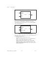
Single-Buffered versus Double-Buffered Data..............................................................4-1
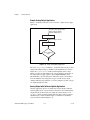
Double-Buffered Input Operations ................................................................................4-2
Potential Setbacks............................................................................................4-4
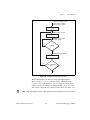
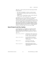
Double-Buffered Output Operations .............................................................................4-6
Potential Setbacks............................................................................................4-7
Double-Buffered Functions ...........................................................................................4-9
Double Buffer Configuration Functions..........................................................4-9
Double Buffer Transfer Functions...................................................................4-10
Double Buffer HalfReady Functions...............................................................4-11
Conclusion .....................................................................................................................4-12
Chapter 5
Transducer Conversion Functions
Function Descriptions ....................................................................................................5-2
RTD_Convert and RTD_Buf_Convert............................................................5-2
Parameter Discussion........................................................................5-2
Using This Function..........................................................................5-3
© National Instruments Corporation
vii
Traditional NI-DAQ (Legacy) User Manual
Contents
Strain_Convert and Strain_Buf_Convert ........................................................ 5-4
Parameter Discussion ....................................................................... 5-4
Using This Function ......................................................................... 5-5
Thermistor_Convert and Thermistor_Buf_Convert........................................ 5-7
Parameter Discussion ....................................................................... 5-7
Using This Function ......................................................................... 5-7
Thermocouple_Convert and Thermocouple_Buf_Convert ............................ 5-9
Parameter Discussion ....................................................................... 5-9
Using This Function ......................................................................... 5-10
Appendix A
Technical Support and Professional Services
Glossary
Index
Traditional NI-DAQ (Legacy) User Manual
viii
ni.com
About This Manual
Traditional NI-DAQ (Legacy) is an older driver with outdated application
programming interfaces (APIs) for developing data acquisition, instrumentation, and
control applications for older National Instruments DAQ devices. You should use
Traditional NI-DAQ (Legacy) only in certain circumstances. Refer to the NI-DAQ Readme
for more information about when to use Traditional NI-DAQ (Legacy), including a
complete list of supported devices, operating systems, application software versions, and
language versions. Refer to the NI-DAQmx Help, which you can access from Start»
Programs» National Instruments»NI-DAQ»NI-DAQmx Help, for an overview of the
two NI-DAQ APIs and the advantages of NI-DAQmx. In NI application software, this
same help is available by searching for NI-DAQmx. You can install the latest version of
NI-DAQmx software, available at ni.com/downloads.
Caution
The Traditional NI-DAQ (Legacy) User Manual describes the Traditional
NI-DAQ (Legacy) application programming interface (API). This manual
includes source code for several example applications.
How to Use the Traditional NI-DAQ (Legacy)
Documentation Set
Begin by reading the NI-DAQ 7.x readme file, the Traditional NI-DAQ
(Legacy) Readme, and the DAQ Getting Started Guide for NI-DAQ 7.x for
information on how to set up your DAQ system using Traditional NI-DAQ
(Legacy).
Read this manual to learn about programming with Traditional NI-DAQ
(Legacy). When you are familiar with the material in this manual, you can
begin to use the Traditional NI-DAQ (Legacy) reference help files for more
information on functions and VIs. Other documentation includes
Measurement & Automation Explorer Help for Traditional NI-DAQ
(Legacy), a help file installed with Measurement & Automation Explorer
(MAX).
For detailed hardware information, refer to the user documentation for each
device.
© National Instruments Corporation
ix
Traditional NI-DAQ (Legacy) User Manual
About This Manual
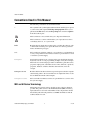
Conventions Used in This Manual
The following conventions are used in this manual.
»
The » symbol leads you through nested menu items and dialog box options
to a final action. The sequence File»Page Setup»Options directs you to
pull down the File menu, select the Page Setup item, and select Options
from the last dialog box.
This icon denotes a note, which alerts you to important information.
This icon denotes a caution, which advises you of precautions to take to
avoid injury, data loss, or a system crash.
bold
Bold text denotes items that you must select or click in the software, such
as menu items and dialog box options. Bold text also denotes parameter
names and function prototypes.
italic
Italic text denotes variables, emphasis, a cross reference, or an introduction
to a key concept. This font also denotes text that is a placeholder for a word
or value that you must supply.
monospace
Text in this font denotes text or characters that you should enter from the
keyboard, sections of code, programming examples, and syntax examples.
This font is also used for the proper names of disk drives, paths, directories,
programs, subprograms, subroutines, device names, functions, operations,
properties, methods, variables, filenames and extensions, and code
excerpts.
monospace bold
Bold text in this font denotes the messages and responses that the computer
automatically prints to the screen. This font also emphasizes lines of code
that are different from the other examples.
monospace italic
Italic text in this font denotes text that is a placeholder for a word or value
that you must supply.
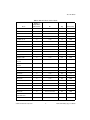
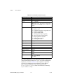
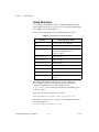
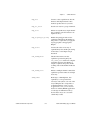
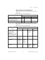
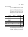
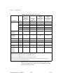
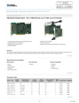
MIO and AI Device Terminology
This manual uses generic terms to describe groups of devices whenever
possible. The generic terms for the multifunction I/O (MIO) and analog
input (AI) devices are based on the number of bits, the platform, and the
functionality. The following table lists each MIO and AI device and the
technical details for each.
Traditional NI-DAQ (Legacy) User Manual
x
ni.com
About This Manual
Table 1. MIO and AI Device Technical Details
Number of
Single-Ended
(SE) Channels
Bit
Type
Functionality
AT-AI-16XE-10
16
16-bit
AT
AI
AT-MIO-16DE-10
16
12-bit
AT
MIO
AT-MIO-16E-1
16
12-bit
AT
MIO
AT-MIO-16E-2
16
12-bit
AT
MIO
AT-MIO-16E-10
16
12-bit
AT
MIO
AT-MIO-16XE-10
16
16-bit
AT
MIO
AT-MIO-16XE-50
16
16-bit
AT
MIO
AT-MIO-64E-3
64
12-bit
AT
MIO
DAQCard-6023E
16
12-bit
PCMCIA
AI
DAQCard-6024E
16
12-bit
PCMCIA
MIO
DAQCard-6062E
16
12-bit
PCMCIA
MIO
DAQPad-6020E
16
12-bit
USB
MIO
DAQPad-6052E for
FireWire
16
16-bit
FireWire
MIO
DAQPad-6070E for
FireWire
16
12-bit
FireWire
MIO
PCI-6013
16
16-bit
PCI
MIO
PCI-6014
16
16-bit
PCI
MIO
PCI-6023E
16
12-bit
PCI
AI
PCI-6024E
16
12-bit
PCI
MIO
PCI-6025E
16
12-bit
PCI
MIO
PCI-6031E (MIO-64XE-10)
64
16-bit
PCI
MIO
PCI-6032E (AI-16XE-10)
16
16-bit
PCI
AI
PCI-6033E (AI-64XE-10)
64
16-bit
PCI
AI
PCI-6034E
16
16-bit
PCI
AI
PCI-6035E
16
16-bit AI, 12-bit AO
PCI
MIO
PCI-6040E
(PCI-MIO-16E-4)
16
12-bit
PCI
MIO
PCI-6052E
16
16-bit
PCI
MIO
Device
© National Instruments Corporation
xi
Traditional NI-DAQ (Legacy) User Manual
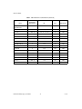
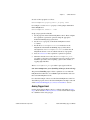
About This Manual
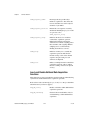
Table 1. MIO and AI Device Technical Details (Continued)
Number of
Single-Ended
(SE) Channels
Bit
Type
Functionality
PCI-6070E
(PCI-MIO-16E-1)
16
12-bit
PCI
MIO
PCI-6071E (MIO-64E-1)
64
12-bit
PCI
MIO
PCI-6110
4, DIFF only
12-bit AI, 16-bit AO
PCI
MIO
PCI-6111
2, DIFF only
12-bit AI, 16-bit AO
PCI
MIO
PCI-6115
4, DIFF only
12-bit
PCI
MIO
PCI-6120
4, DIFF only
16-bit
PCI
MIO
PCI-MIO-16XE-10
16
16-bit
PCI
MIO
PCI-MIO-16XE-50
16
16-bit
PCI
MIO
PXI-6025E
16
12-bit
PXI
MIO
PXI-6030E
16
16-bit
PXI
MIO
PXI-6031E
64
16-bit
PXI
MIO
PXI-6040E
16
12-bit
PXI
MIO
PXI-6052E
16
16-bit
PXI
MIO
PXI-6070E
16
12-bit
PXI
MIO
PXI-6115
4, DIFF only
12-bit
PXI
MIO
PXI-6120
4, DIFF only
16-bit
PXI
MIO
Device
Traditional NI-DAQ (Legacy) User Manual
xii
ni.com
1
Introduction to
Traditional NI-DAQ (Legacy)
This chapter presents an overview of Traditional NI-DAQ (Legacy).
About the Traditional NI-DAQ (Legacy) Software
Thank you for buying a National Instruments DAQ device, which includes
Traditional NI-DAQ (Legacy) software. Traditional NI-DAQ (Legacy) is a
set of functions that control all of the National Instruments DAQ devices
for analog I/O, digital I/O, timing I/O, SCXI signal conditioning, and RTSI
multiboard synchronization.
Traditional NI-DAQ (Legacy) has both high-level DAQ I/O functions for
maximum ease of use, and low-level DAQ I/O functions for maximum
flexibility and performance. Examples of high-level functions are
streaming data to disk or acquiring a certain number of data points.
Examples of low-level functions are writing directly to the DAQ device
registers or calibrating the analog inputs. Traditional NI-DAQ (Legacy)
does not sacrifice the performance of National Instruments DAQ devices,
because it lets multiple devices operate at their peak performance.
Traditional NI-DAQ (Legacy) includes a Buffer and Data Manager that
uses sophisticated techniques for handling and managing data acquisition
buffers, so you can acquire and process data simultaneously. Traditional
NI-DAQ (Legacy) can transfer data using DMA, interrupts, or software
polling. Traditional NI-DAQ (Legacy) can use DMA to transfer data into
memory above 16 MB, even on ISA bus computers.
With the Resource Manager, you can use several functions and several
devices simultaneously. The Resource Manager prevents multiboard
contention over DMA channels, interrupt levels, and RTSI channels.
© National Instruments Corporation
1-1
Traditional NI-DAQ (Legacy) User Manual
Chapter 1
Introduction to Traditional NI-DAQ (Legacy)
Traditional NI-DAQ (Legacy) can send event-driven messages to Windows
or Windows NT applications each time a user-specified event occurs. Thus,
polling is eliminated and you can develop event-driven DAQ applications.
Some examples of Traditional NI-DAQ (Legacy) user events are:
•
When a specified number of analog samples has been acquired
•
When the analog level and slope of a signal match specified levels
•
When the signal is inside or outside a voltage band
•
When a specified digital I/O pattern is matched
•
When a rising or falling edge occurred on a timing I/O line
How to Set Up Your DAQ System
Refer to the DAQ Getting Started Guide for NI-DAQ 7.x for more
information on installing and configuring your hardware and software.
Traditional NI-DAQ (Legacy) Overview
Traditional NI-DAQ (Legacy) is a library of routines that work with
National Instruments DAQ devices. Traditional NI-DAQ (Legacy) helps
you perform tasks ranging from simple device initialization to advanced
high-speed data logging. The number of tasks you need for your
applications depends on the types of DAQ devices you have and the
complexity of your applications.
Device Configuration
Before you begin your Traditional NI-DAQ (Legacy) application
development, you must configure your National Instruments DAQ devices.
Traditional NI-DAQ (Legacy) needs the device configuration information
to program your hardware correctly.
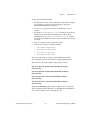
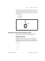
Using Measurement & Automation Explorer
Measurement & Automation Explorer (MAX) is a Windows-based
application that you use to configure and view National Instruments DAQ
device settings under Windows 2000/NT/XP/Me/98.
Note
To use MAX, quit any applications that are performing DAQ operations.
Traditional NI-DAQ (Legacy) User Manual
1-2
ni.com
Chapter 1
Introduction to Traditional NI-DAQ (Legacy)
Double-click the Measurement & Automation icon on your desktop to
run MAX. Refer to the Measurement & Automation Explorer Help for
Traditional NI-DAQ (Legacy) for more information and detailed
instructions on configuring your devices and accessories.
© National Instruments Corporation
1-3
Traditional NI-DAQ (Legacy) User Manual
2
Fundamentals of Building
Windows Applications
This chapter describes the fundamentals of creating Traditional NI-DAQ
(Legacy) applications in Windows 2000/NT/XP/Me/98.
The following section contains general information about building
Traditional NI-DAQ (Legacy) applications, describes the nature of the
Traditional NI-DAQ (Legacy) files used in building Traditional NI-DAQ
(Legacy) applications, and explains the basics of making applications using
the following tools:
•
Microsoft Visual C++
•
Microsoft Visual Basic
If you are not using the tools listed, refer to your development tool
reference manual for details on creating applications that call DLLs.
The Traditional NI-DAQ (Legacy) Libraries
The Traditional NI-DAQ (Legacy) function libraries are DLLs, which
means that Traditional NI-DAQ (Legacy) routines are not linked into the
executable files of applications. Only the information about the Traditional
NI-DAQ (Legacy) routines in the Traditional NI-DAQ (Legacy) import
libraries is stored in the executable files.
Note Use the 32-bit nidaq32.dll. If you are programming in C or C++, link in the
appropriate import library. Refer to the following sections for language-specific details.
Using function prototypes is a good programming practice. That is why
Traditional NI-DAQ (Legacy) is packaged with function prototype files for
different Windows development tools. The installation utility copies the
appropriate prototype files for the development tools you choose. If you are
not using any of the development tools that Traditional NI-DAQ (Legacy)
works with, you must create your own function prototype file.
© National Instruments Corporation
2-1
Traditional NI-DAQ (Legacy) User Manual
Chapter 2
Fundamentals of Building Windows Applications
Creating a Windows Application Using
Microsoft Visual C++
This section assumes that you will be using the Microsoft Visual C++ IDE
to manage your code development, and that you are familiar with the IDE.
Developing a Traditional NI-DAQ (Legacy) Application
To develop a Traditional NI-DAQ (Legacy) application, follow these
general steps:
1.
Open an existing or new Visual C++ project to manage your
application code.
2.
Create files of type .c (C source code) or .cpp (C++ source code)
and add them to the project. Make sure you include the Traditional
NI-DAQ (Legacy) header file, nidaq.h, as such in your source code
files:
#include "nidaq.h"
You also might want to include nidaqcns.h and nidaqerr.h. You
also can include other files (for example, .rc, .def) that you have
created for graphical user interface (GUI) applications.
3.
Specify the directory which contains the Traditional NI-DAQ (Legacy)
header files under the preprocessor»include directory settings in
your compiler. (For Visual C++ 4.x, this is under
Build»Settings»C/C++. For Visual C++ 5.0/6.0, this is under
Project»Settings»C/C++.) The Traditional NI-DAQ (Legacy) header
files are located in the .\Include directory under your NI-DAQ
directory.
4.
Add the Traditional NI-DAQ (Legacy) import library nidaq32.lib
to the project. The Traditional NI-DAQ (Legacy) import library files
are located in the .\Lib directory under your NI-DAQ directory.
5.
Build your application.
Example Programs
You can find example programs and project files in
.\Examples\VisualC directory under your NI-DAQ directory.
To load an example program, use one of the generic makefiles with
the.mak extension.
Traditional NI-DAQ (Legacy) User Manual
2-2
ni.com
Chapter 2
Fundamentals of Building Windows Applications
To load an example project with Visual C++ 4.x or later, select the menu
option File»Open Project Workspace, and select List Files of Type to be
Makefiles. Then select the.mak file of your choice.
Special Considerations
When developing an application using Visual C++, consider the following
special considerations.
Buffer Allocation
To allocate memory, you can use the Windows API function
GlobalAlloc(). After allocation, lock memory with GlobalLock()
to use a buffer of memory. You can use the memory handle returned by
GlobalLock()in place of the buffer parameter in Traditional NI-DAQ
(Legacy) API functions that accept buffers (Align_DMA_Buffer,
DAQ_DB_Transfer, DAQ_Monitor, DAQ_Op, DAQ_Start,
DIG_Block_In, DIG_Block_Out, DIG_DB_Transfer,
GPCTR_Config_Buffer, GPCTR_Read_Buffer, Lab_ISCAN_Op,
Lab_ISCAN_Start, SCAN_Op, SCAN_Start, SCAN_Sequence_Demux,
WFM_DB_Transfer, WFM_Load, WFM_Op). After using the memory,
unlock memory with GlobalUnlock() and free it with GlobalFree().
Note If you allocate memory from GlobalAlloc(), you must call GlobalLock() on
the memory object before passing it to Traditional NI-DAQ (Legacy).
String Passing
To pass strings, pass a pointer to the first element of the character array.
Be sure that the string is null-terminated.
Parameter Passing
By default, C passes parameters by value. Remember to pass pointers to
variables when you need to pass by address.
Creating a Windows Application Using Microsoft
Visual Basic
This section assumes that you will be using the Microsoft Visual Basic
IDE to manage your code development, and that you are familiar with
the IDE.
© National Instruments Corporation
2-3
Traditional NI-DAQ (Legacy) User Manual
Chapter 2
Fundamentals of Building Windows Applications
Developing a Traditional NI-DAQ (Legacy) Application
To develop a Traditional NI-DAQ (Legacy) application, follow these
general steps:
1.
Open an existing or new Visual Basic project to manage your
application code.
2.
Create files of type.frm (form definition and event handling code),
.bas (Visual Basic generic code module), or .cls (Visual Basic class
module) and add them to the project.
3.
Include the Traditional NI-DAQ (Legacy) include file for Visual Basic,
nidaq32.bas, into your project. You also might want to include
nidaqcns.inc and nidaqerr.inc. The Traditional NI-DAQ
(Legacy) include files for Visual Basic are located in the .\Include
directory under your NI-DAQ directory. For Visual Basic 5.0/6.0, you
can select the Project»Add Module menu option, click the Existing
tab, and select the module of your choice.
Alternatively, you can add a reference to the National Instruments Data
Acquisition Type Library, which is part of the Traditional NI-DAQ
(Legacy) DLL. In Visual Basic 5.0/6.0, select the Project»References
menu option, and check National Instruments Data Acquisition
Library. If you do not see it listed there, click the Browse button and
locate nidaq32.dll in your \Windows\system or
\Windows\system32 directory.
4.
Run your application by clicking the Run button.
In Visual Basic, function declarations have scope globally throughout the project.
In other words, you can define your prototypes in any module. The functions will be
recognized even in other modules.
Note
For information on using the NI-DAQ Visual Basic Custom Controls, refer to the
Traditional NI-DAQ (Legacy) Events in Visual Basic section of Chapter 3, Software
Overview.
Refer to the Traditional NI-DAQ (Legacy) reference help files for more information on
using the Traditional NI-DAQ (Legacy) functions in Visual Basic for Windows.
Example Programs
You can find example programs and project files in the .\Examples\
VBasic directory under your Traditional NI-DAQ (Legacy) directory.
Traditional NI-DAQ (Legacy) User Manual
2-4
ni.com
Chapter 2
Fundamentals of Building Windows Applications
To load an example program, use one of the Visual Basic project files with
the.vbp extension. These are Visual Basic 4.0 projects, which you can
open only with Visual Basic version 4.0 or later.
To load an example project with Visual Basic 4.0 or later versions, select
the menu option File»Open Project, then select the.vbp file of your
choice.
Special Considerations
When developing an application using Visual Basic, consider the following
special considerations.
Buffer Allocation
Visual Basic 4.0 is restrictive when allocating memory. You
allocate memory by declaring an array of the data type with which you
want to work. Visual Basic uses dynamic memory allocation so you can
redimension an array to a variable size during run time. However, arrays
are restricted to being less than 64 KB in total size (this translates to about
32,767 (16-bit) integers, 16,384 (32-bit) long integers, or 8,191 doubles).
To break the 64 KB buffer size barrier, you can use the Windows API
functions GlobalAlloc() to allocate buffers larger than 64 KB. After
allocation, you must lock memory with GlobalLock()to use a buffer of
memory. You can use the memory handle returned by GlobalLock() in
place of the buffer parameter in Traditional NI-DAQ (Legacy) API
functions that accept buffers (Align_DMA_Buffer, DAQ_DB_Transfer,
DAQ_Monitor, DAQ_Op, DAQ_Start, DIG_Block_In, DIG_Block_Out,
DIG_DB_Transfer, GPCTR_Config_Buffer, GPCTR_Read_Buffer,
Lab_ISCAN_Op, Lab_ISCAN_Start, SCAN_Op, SCAN_Start,
SCAN_Sequence_Demux, WFM_DB_Transfer, WFM_Load, WFM_Op). The
Traditional NI-DAQ (Legacy) header file declares the buffer parameter “As
Any.” After using the memory, you must unlock memory with
GlobalUnlock()and free it with GlobalFree().
Note If you allocate memory from GlobalAlloc(), you must call GlobalLock on the
memory object before passing it to Traditional NI-DAQ (Legacy).
The following paragraph illustrates declarations of functions.
© National Instruments Corporation
2-5
Traditional NI-DAQ (Legacy) User Manual
Chapter 2
Fundamentals of Building Windows Applications
For Visual Basic 4.0 or later, 32-bit:
Declare Function GlobalAlloc Lib "kernel32" Alias
"GlobalAlloc" (ByVal wFlags As Long, ByVal dwBytes As
Long) As Long
Declare Function GlobalFree Lib "kernel32" Alias
"GlobalFree" (ByVal hMem As Long) As Long
Declare Function GlobalLock Lib "kernel32" Alias
"GlobalLock" (ByVal hMem As Long) As Long
Declare Function GlobalReAlloc Lib "kernel32" Alias
"GlobalReAlloc" (ByVal hMem As Long, ByVal dwBytes As
Long, ByVal wFlags As Long) As Long
Declare Function GlobalUnlock Lib "kernel32" Alias
"GlobalUnlock" (ByVal hMem As Long) As Long
String Passing
In Visual Basic, variables of data type String need no special
modifications to be passed to Traditional NI-DAQ (Legacy) functions.
Visual Basic automatically appends a null character to the end of a string
before passing it (by reference, because strings cannot be passed by value
in Visual Basic) to a procedure or function.
Parameter Passing
By default, Visual Basic passes parameters by reference. Prepend the
ByVal keyword if you need to pass by value.
Passing Unsigned 16-Bit and 32-Bit Integer
Parameters
The Visual Basic INTEGER type is a signed value. Visual Basic considers
any value greater than 32,767 a negative number. To pass unsigned 16-bit
parameters, refer to the following examples:
•
If the function is supposed to return an unsigned 16-bit integer, and you
are reading back a negative number, add 65,536 to the negative
number.
Dim myUnsignedCnt As Long
Dim retCnt As Integer
‘retCnt is the value returned from the called
‘function.
‘You can call a DAQ function that returns an unsigned
‘16-bit value and store the value in retCnt.
Traditional NI-DAQ (Legacy) User Manual
2-6
ni.com
Chapter 2
Fundamentals of Building Windows Applications
if retCnt < 0 then
myUnsignedCnt = CInt(retCnt) + 65536
else
myUnsignedCnt = retCnt
end if
•
To pass an unsigned 16-bit value to a function with an unsigned 16-bit
type parameter, you must first compute the value to pass to the
function.
Dim myUnsignedCnt As Long
Dim ToPassVal As Integer
‘You compute the value that you want to pass to the
‘function and store it in myUnsignedCnt.
if myUnsignedCnt > 32767 then
ToPassVal = CInt(myUnsignedCnt - 65536)
else
ToPassVal = CInt(myUnsignedCnt)
end if
The Visual Basic LONG integer type is a signed 32-bit type. Visual Basic
considers any value greater than 2,147,483,647 a negative number. To pass
unsigned 16-bit parameters, refer to the following examples:
•
If the function is supposed to return an unsigned 32-bit integer, and you
are reading back a negative number, then add 4,294,967,296 to the
negative number.
Dim myUnsignedCnt As Double
Dim retCnt As Long
‘retCnt is the value returned from the called
‘function
‘You can call a DAQ function that returns an unsigned
‘16-bit value and stores it in retCnt.
if retCnt < 0 then
myUnsignedCnt = CInt(retCnt) + 4294967296
else
myUnsignedCnt = retCnt
end if
© National Instruments Corporation
2-7
Traditional NI-DAQ (Legacy) User Manual
Chapter 2
Fundamentals of Building Windows Applications
•
To pass an unsigned 32-bit value to a function with an unsigned 32-bit
type parameter, you must first compute the value to pass to the
function.
Dim myUnsignedCnt As Double
Dim ToPassVal As Long
‘You compute the value that you want to pass to the
‘function and store it in myUnsignedCnt.
if myUnsignedCnt > 2147483647 then
ToPassVal = CLng(myUnsignedCnt - 4294967296)
else
ToPassVal = CLng(myUnsignedCnt)
end if
Traditional NI-DAQ (Legacy) Examples
The Traditional NI-DAQ (Legacy) installer installs a suite of concisely
written examples in the following application development environments:
•
LabWindows™/CVI™ 5.0.x
•
Microsoft Visual C++ 2.x (32-bit) or later
•
Microsoft Visual Basic 4.0 (32-bit) or later
These examples illustrate how to use Traditional NI-DAQ (Legacy)
functions to perform a single task. All examples are devoid of any code to
extract values from GUI objects so that you can focus on how the code flow
is formed. In addition, most parameters are hardcoded at the top of the
routine so that if you decide to change them, you can simply change the
assignment.
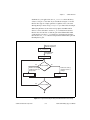
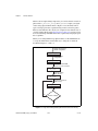
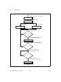
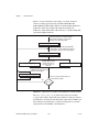
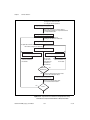
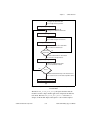
The examples correspond to the function flowcharts that you will see in
Chapter 3, Software Overview. If a task and a flowchart in the following
chapter suits your data acquisition needs, you should find a corresponding
example to get you started.
Each example consists of the following files:
•
An appropriate project file for the programming language
•
A single source code file to illustrate the task at hand
•
A library of Traditional NI-DAQ (Legacy) example utility functions
(for buffer creation, waveform plotting, error checking, and
implementing a delay)
Traditional NI-DAQ (Legacy) User Manual
2-8
ni.com
Chapter 2
Fundamentals of Building Windows Applications
Note None of the examples are installed in their executable (.exe) format. To run them,
you first must build them or load them into the IDE for the appropriate programming
language.
The examples are stored in the hierarchy shown below for each language:
.\AI
Analog Input examples
.\AO
Analog Output examples
.\DI
Digital Input examples
.\DO
Digital Output examples
.\CTR
Counter/timer examples
.\SCXI
SCXI examples
.\CALIB
Calibration examples
The project files have the same file name (not including extension) as the
source code files. The following types are installed:
•
LabWindows/CVI:
.prj (project file), .c (source file)
•
Visual C++:
.mak (generic make file), .c (source file)
•
Visual Basic:
.vbp (project file, for Visual Basic 4.0 [32-bit] or later),
.frm (form module)
© National Instruments Corporation
2-9
Traditional NI-DAQ (Legacy) User Manual
3
Software Overview
This chapter describes the function classes in Traditional NI-DAQ
(Legacy) and briefly describes each function.
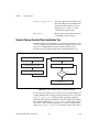
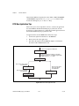
Traditional NI-DAQ (Legacy) functions are grouped according to the
following classes:
•
Initialization and general-configuration
•
Software-calibration and device-specific
•
Event Message
•
Analog input function group
–
One-shot analog input
•
–
•
•
Data acquisition
•
High-level data acquisition
•
Low-level data acquisition
•
Low-level double-buffered data acquisition
Analog output function group
–
One-shot analog output
–
Waveform generation
•
High-level waveform generation
•
Low-level waveform generation
Digital I/O function group
–
Digital I/O
–
Group digital I/O
•
© National Instruments Corporation
Single-channel analog input
Double-buffered digital I/O
–
Change Notification
–
Filtering
3-1
Traditional NI-DAQ (Legacy) User Manual
Chapter 3
Software Overview
•
Counter/Timer function group
–
Counter/timer
–
Interval counter/timer
–
General-purpose counter/timer
•
RTSI bus trigger
•
SCXI
•
Transducer conversion
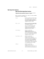
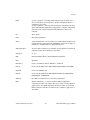
Initialization and General-Configuration Functions
Use these general functions for initializing and configuring your hardware
and software.
Refer to the Traditional NI-DAQ (Legacy) C Reference Help to determine
which functions your device supports.
Align_DMA_Buffer
Aligns the data in a DMA buffer to avoid
crossing a physical page boundary. This
function is for use with DMA waveform
generation and digital I/O pattern
generation.
Get_DAQ_Device_Info
Retrieves parameters pertaining to the
device operation.
Get_NI_DAQ_Version
Returns the version number of the
Traditional NI-DAQ (Legacy) library.
Init_DA_Brds
Initializes the hardware and software
states of a National Instruments
DAQ device to its default state and then
returns a numeric device code that
corresponds to the type of device
initialized. Any operation that the device
is performing is halted. Traditional
NI-DAQ (Legacy) automatically calls
this function; your application does not
have to call it explicitly. This function is
useful for reinitializing the device
hardware, for reinitializing the
Traditional NI-DAQ (Legacy) software,
Traditional NI-DAQ (Legacy) User Manual
3-2
ni.com
Chapter 3
Software Overview
and for determining which device has
been assigned to a particular slot number.
Set_DAQ_Device_Info
Selects parameters pertaining to the
device operation.
Timeout_Config
Establishes a timeout limit that is used by
the synchronous functions to ensure that
these functions eventually return control
to your application. Examples of
synchronous functions are DAQ_Op,
DAQ_DB_Transfer, and
WFM_from_Disk.
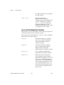
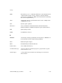
Software-Calibration and Device-Specific Functions
Each of these software-calibration and configuration functions is specific
to only one type of device or class of devices.
Refer to the Traditional NI-DAQ (Legacy) C Reference Help to determine
which functions your device supports.
AO_Calibrate
Loads a set of calibration constants into
the calibration DACs or copies a set of
calibration constants from one of four
EEPROM areas to EEPROM area 1. You
can load an existing set of calibration
constants into the calibration DACs from
a storage area in the onboard EEPROM.
You can copy EEPROM storage areas
2 through 5 (EEPROM area 5 contains
the factory-calibration constants) to
storage area 1. NI-DAQ automatically
loads the calibration constants stored
in EEPROM area 1 the first time a
function pertaining to the AT-AO-6/10 is
called.
Calibrate_1200
Calibrates the gain and offset values for
the 1200/AI devices ADCs and DACs.
You can perform a new calibration or use
an existing set of calibration constants by
copying the constants from their storage
location in the onboard EEPROM. You
© National Instruments Corporation
3-3
Traditional NI-DAQ (Legacy) User Manual
Chapter 3
Software Overview
can store up to six sets of calibration
constants. Traditional NI-DAQ (Legacy)
automatically loads the calibration
constants stored in EEPROM user area 5
the first time you call a function
pertaining to the device.
Calibrate_TIO
Use the function to calibrate the crystal
oscillator on your timing I/O 660X
device.
Calibrate_DSA
Use this function to calibrate your
DSA device.
Calibrate_E_Series
Use this function to calibrate your
E Series, 671X, or 673X device and to
select a set of calibration constants for
Traditional NI-DAQ (Legacy) to use.
Configure_HW_Analog_Trigger
Configures the hardware analog trigger
available on your E Series device.
LPM16_Calibrate
Calibrates the LPM device converter.
The function calculates the correct offset
voltage for the voltage comparator,
adjusts positive linearity and full-scale
errors to less than ±0.5 each, and adjusts
zero error to less than ±1 LSB.
MIO_Config
Turns dithering on and off. For the
MIO-64, this function also lets you
specify whether to use AMUX-64T
channels or onboard channels.
SCXI_Calibrate
Performs a self-calibration (or internal
calibration) for certain SCXI modules.
Select_Signal
Selects the source and polarity of certain
signals used by the E Series and DSA
devices. You typically need to use this
function to externally control timing, to
use the RTSI bus, or to configure one of
the I/O connector PFI pins.
Traditional NI-DAQ (Legacy) User Manual
3-4
ni.com
Chapter 3
Software Overview
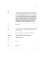
Event Message Functions
Traditional NI-DAQ (Legacy) Event Message functions are an efficient
way to monitor your background data acquisition processes, without
dedicating your foreground process for status checking.
The Event Message dispatcher notifies your application when a
user-specified DAQ event occurs. Using event messaging eliminates
continuous polling of data acquisition processes.
Config_Alarm_Deadband
Specify alarm on/off condition for data
acquisition event messaging.
Config_ATrig_Event_Message
Specify analog input trigger level and
slope for data acquisition event
messaging.
Config_DAQ_Event_Message
Specify analog input, analog output,
digital input, or digital output trigger
condition for event messaging.
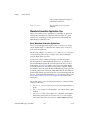
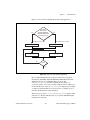
Event Messaging Application Tips
To receive notification from the Traditional NI-DAQ (Legacy) data
acquisition process in case of special events, you can call
Config_Alarm_Deadband, Config_ATrig_Event_Message, or
Config_DAQ_Event_Message to specify an event in which you are
interested. If you are interested in more than one event, you can call any of
those three functions again for each event.
After you have configured all event messages, you can begin your data
acquisition by calling SCAN_Start, DIG_Block_In, and so on.
When any of the events you specified occur, Traditional NI-DAQ (Legacy)
notifies your application.
Event notification can be done through user-defined callbacks and/or the
Windows Message queue. When a user-specified event occurs, Traditional
NI-DAQ (Legacy) calls the user-defined callback (if defined) and/or puts a
message into the Windows Message queue, if you specified a window
handle. Your application receives the message when it calls the Windows
GetMessage API.
© National Instruments Corporation
3-5
Traditional NI-DAQ (Legacy) User Manual
Chapter 3
Software Overview
After your application receives an event message, it can carry out the
appropriate task, such as updating the screen or saving data to disk.
To restart your data acquisition process after it completes, you do not need
to call the message configuration calls again. They remain defined as long
as your application does not explicitly remove them or call
Init_DA_Brds.
To add or remove a message, first clear your data acquisition process.
Then, call one of the three event message configuration functions.
Traditional NI-DAQ (Legacy) Events in Visual Basic
ActiveX Controls for Visual Basic
Unlike standard control-flow programming languages, event occurrences
drive Visual Basic code. You interact with outside events through the
properties and procedures of a control. For any given control, there is a
set of procedures called event procedures that affect that control.
For example, a command button named Run has a procedure called
Run_Click() that is called when you click the Run button. If you
want something to run when you click the Run button, enter code in the
Run_Click() procedure. When a program starts executing, Visual Basic
looks for events related to controls and calls control procedures as
necessary. You do not write an event loop.
There are three Traditional NI-DAQ (Legacy) ActiveX controls for Visual
Basic applications:
•
General Data Acquisition Event (daqevent.ocx)
•
Analog Trigger Event (atrigev.ocx)
•
Analog Alarm Event (alarmev.ocx)
Traditional NI-DAQ (Legacy) User Manual
3-6
ni.com
Chapter 3
Software Overview
The Traditional NI-DAQ (Legacy) installer places all of these ActiveX
controls in the NIDAQ subdirectory of your Windows 2000/NT/XP/Me/98
directory under the file names shown.
These three ActiveX controls actually call the Traditional NI-DAQ
(Legacy) Config_DAQ_Event_Message,
Config_ATrig_Event_Message, and Config_Alarm_Deadband
functions. Visual Basic applications cannot receive Windows messages, but
if you use Traditional NI-DAQ (Legacy) ActiveX controls shown
previously in this section, your Visual Basic application can receive
Traditional NI-DAQ (Legacy) messages.
Note
You can use the OCXs in Visual Basic, version 4.0 (32-bit) or later.
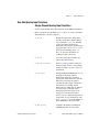
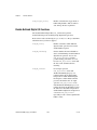
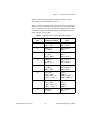
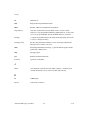
General DAQ Event
You use the General DAQ Event control to configure and enable a single
data acquisition event. Refer to the Event Message Functions section for a
complete description of Traditional NI-DAQ (Legacy) events. Table 3-1
lists the properties for the General DAQ Event control.
Note
An n represents a generic number and is not the same value in every occurrence.
© National Instruments Corporation
3-7
Traditional NI-DAQ (Legacy) User Manual
Chapter 3
Software Overview
Table 3-1. General DAQ Event Control Properties
Property
Allowed Property Values
Name
GeneralDAQEventn (default)
Board
1 – n (default)
ChanStr
Refer to Config_DAQ_Event_Message in
the Traditional NI-DAQ (Legacy) C Reference
Help.
DAQEvent
0—Acquired or generated n scans
1—Every n scans
2—Completed operation or stopped by error
3—Voltage out of bounds
4—Voltage within bounds
5—Analog positive slope triggering
6—Analog negative slope triggering
7—Digital pattern not matched
8—Digital pattern matched
9—Counter pulse event
DAQTrigVal0
Long
DAQTrigVal1
Long
TrigSkipCount
Long
PreTrigScans
Long
PostTrigScans
Long
Index
N/A
Tag
N/A
Enabled
0—False (default)
1—True
Some General DAQ Events can be implemented only by a select group
of National Instruments DAQ devices. Also, some General DAQ Events
require that you set the asynchronous data acquisition or generation
operation to use interrupts. For more information on the different
types of General DAQ Events, refer to the description for the
Config_DAQ_Event_Message function in the Traditional NI-DAQ
(Legacy) C Reference Help.
Traditional NI-DAQ (Legacy) User Manual
3-8
ni.com
Chapter 3
Software Overview
Set each of these properties as follows:
GeneralDAQEventn.property name = property value
For example, to set the ChanStr property to Analog Input channel 0 for
GeneralDAQEvent 1:
GeneralDAQEvent1.ChanStr = "AI0"
Set up your program flow like this:
1.
Set the properties of the General DAQ Event control. Then, configure
the acquisition or generation operations using the appropriate
Traditional NI-DAQ (Legacy) functions.
2.
Set the Enabled property of the General DAQ Event control
to 1 (True).
3.
Invoke the GeneralDAQEventn.Refresh method to set the
DAQ Event in the Traditional NI-DAQ (Legacy) driver. Each
subsequent use of GeneralDAQEventn.Refresh deletes the old
DAQ Event and sets a new one with the current set of properties.
4.
Start an asynchronous data acquisition or generation operation.
5.
When the selected event occurs, the GeneralDAQEventn_Fire
procedure is called. You can perform the necessary event processing
within this procedure, such as updating a global count variable, or
toggling digital I/O lines.
The GeneralDAQEventn_Fire procedure is prototyped as follows:
Sub GeneralDAQEventn_Fire (DoneFlag As Integer, Scans As Long)
The parameter DoneFlag equals 1 if the acquisition was over when the
DAQ Event fired. Otherwise, it is 0. Scans equals the number of the scan
that caused the DAQ Event to fire.
For a detailed example of how to use the General DAQ Event control in a
Visual Basic program, refer to the General DAQ Event example at the end
of the Traditional NI-DAQ (Legacy) Events in Visual Basic section.
Analog Trigger Event
Use the Analog Trigger Event control to configure and enable an analog
trigger. Refer to the Event Message Functions section earlier in this chapter
for a definition of the analog trigger.
© National Instruments Corporation
3-9
Traditional NI-DAQ (Legacy) User Manual
Chapter 3
Software Overview
Table 3-2 lists the properties for the Analog Trigger Event control.
Table 3-2. Analog Trigger Event Control Properties
Property
Allowed Property Values
Name
GeneralDAQEventn (default)
Board
1 – n (default)
ChanStr
Refer to Config_DAQ_Event_Message in
the Traditional NI-DAQ (Legacy) C
Reference Help
Level
Single (voltage)
WindowSize
Single (voltage)
Slope
0—Positive (default)
1—Negative
TrigSkipCount
Long
PreTrigScans
Long
PostTrigScans
Long
Index
N/A
Tag
N/A
Enabled
0—False (default)
1—True
The Analog Trigger Event requires that you set the asynchronous
data acquisition operation to use interrupts. For more information
on Analog Trigger Events, refer to the descriptions for the
Config_ATrig_Event_Message function in the Traditional NI-DAQ
(Legacy) C Reference Help.
Each of these properties should be set as follows:
AnalogTriggerEventn.property name = property value
For example, to set the ChanStr property to Analog Input channel 0 for
Analog Trigger Event 1:
AnalogTriggerEvent1.ChanStr = "AI0"
Traditional NI-DAQ (Legacy) User Manual
3-10
ni.com
Chapter 3
Software Overview
Set up your program flow like this:
1.
Set the properties of the Analog Trigger Event control. Next, configure
the acquisition or generation operations using the appropriate
Traditional NI-DAQ (Legacy) functions.
2.
Set the Enabled property of the Analog Trigger Event control to
1 (True).
3.
Invoke the AnalogTriggerEventn. Refresh method to actually set
the Analog Trigger Event in the Traditional NI-DAQ (Legacy) driver.
Each subsequent invocation of AnalogTriggerEventn. Refresh
deletes the old Analog Trigger Event and sets a new one with the
current set of properties.
4.
Start an asynchronous data acquisition operation.
5.
When the Analog Trigger conditions are met, the
AnalogTriggerEventn_Fire procedure is called. You can perform
the necessary event processing within this procedure, such as updating
a global count variable, or toggling digital I/O lines.
The AnalogTriggerEventn_Fire procedure is prototyped as follows:
Sub AnalogTriggerEventn_Fire (DoneFlag As Integer,
Scans As Long)
The parameter DoneFlag equals 1 if the acquisition was over when the
Analog Trigger Event fired. Otherwise, it is 0. Scans equals the number of
the scan that caused the Analog Trigger Event to fire.
© National Instruments Corporation
3-11
Traditional NI-DAQ (Legacy) User Manual
Chapter 3
Software Overview
Analog Alarm Event
Use the Analog Alarm Event control to configure and enable an analog
trigger. Refer to the Event Message Functions section earlier in this chapter
for a definition of the analog trigger.
Table 3-3 lists the properties for the Analog Alarm Event control.
Table 3-3. Analog Alarm Event Control Properties
Property
Allowed Property Values
Name
GeneralDAQEventn (default)
Board
1 – n (default)
ChanStr
Refer to Config_DAQ_Event_Message in
the Traditional NI-DAQ (Legacy)
C Reference Help
HighAlarmLevel
Single (voltage)
LowAlarmLevel
Single (voltage)
HighDeadbandWidth
Single (voltage)
LowDeadbandWidth
Single (voltage)
Index
N/A
Tag
N/A
Enabled
0—False (default)
1—True
The Analog Alarm Event requires that you set the asynchronous
data acquisition operation to use interrupts. For more information
on Analog Alarm Events, refer to the description for the
Config_Alarm_Deadband function in the Traditional NI-DAQ (Legacy)
C Reference Help.
Each of these properties should be set as follows:
AnalogAlarmEventn.property name = property value
For instance, to set the ChanStr property to Analog Input channel 0 for
Analog Alarm Event 1:
AnalogAlarmEvent1.ChanStr = "AI0"
Traditional NI-DAQ (Legacy) User Manual
3-12
ni.com
Chapter 3
Software Overview
Set up your program flow like this:
1.
Set the properties of the Analog Alarm Event control. Next, configure
the acquisition or generation operations using the appropriate
Traditional NI-DAQ (Legacy) functions.
2.
Set the Enabled property of the Analog Alarm Event control to
1 (True).
3.
Invoke the AnalogAlarmEventn.Refresh method to set the Analog
Alarm Event in the Traditional NI-DAQ (Legacy) driver. Each
subsequent invocation of AnalogAlarmEventn.Refresh deletes
the old Analog Alarm Event and sets a new one with the current set of
properties.
4.
Start an asynchronous data acquisition operation.
5.
Call any one of the four following procedures:
•
AnalogAlarm_HighAlarmOn
•
AnalogAlarm_HighAlarmOff
•
AnalogAlarm_LowAlarmOn
•
AnalogAlarm_LowAlarmOff
You can perform necessary event processing within this procedure,
such as updating a global count variable or toggling digital I/O lines.
The four Analog Alarm procedures are prototyped as follows:
Sub AnalogAlarmn_HighAlarmOn (DoneFlag As Integer,
Scans As Long)
Sub AnalogAlarmn_HighAlarmOff (DoneFlag As Integer,
Scans As Long)
Sub AnalogAlarmn_LowAlarmOn (DoneFlag As Integer,
Scans As Long)
Sub AnalogAlarmn_LowAlarmOff (DoneFlag As Integer,
Scans As Long)
The parameter DoneFlag equals 1 if the acquisition was over when the
Analog Alarm Event fired. Otherwise, it is 0. Scans equals the number of
the scan that caused the Analog Alarm Event to fire.
© National Instruments Corporation
3-13
Traditional NI-DAQ (Legacy) User Manual
Chapter 3
Software Overview
Using Multiple Controls
In general, a program might contain any number of General DAQ Event,
Analog Trigger Event, and Analog Alarm Event controls. Just like regular
Visual Basic controls, there are two ways you can place multiple controls
on a Visual Basic form:
•
You can create control arrays by copying and pasting a control that
already exists on the form. Each individual element in the control array
is then distinguished by the Index property, and the event procedures
is an extra parameter Index as Integer. The first element has
Index = 0, the second element has Index = 1, and so on. You have
only one procedure for each type of event custom control; however,
you can determine which control array element caused the event to
occur by examining the Index property.
•
You can place multiple controls from the Visual Basic Tool Box onto
the form. Each individual custom control of the same type is then
distinguished by the number after the name of the custom control,
such as GeneralDAQEvent1, GeneralDAQEvent2, and so on.
Consequently, you can have separate procedures for each custom
control, such as GeneralDAQEvent1_Fire,
GeneralDAQEvent2_Fire, and so on.
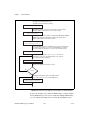
General DAQ Event Example
The following steps provide an outline of how to use the General DAQ
Event control in a Visual Basic program. A working knowledge of Visual
Basic is assumed; otherwise, this example is complete, except for error
checking:
1.
2.
To use the GeneralDAQEvent control, you must first include the proper
control into your project.
•
If you are using Visual Basic 4.0 (32-bit), select the Tools»
Custom Controls option, and select the National Instruments
GeneralDAQEvent custom control.
•
If you are using Visual Basic 5.0, select the Project»
Components option, and select the National Instruments
GeneralDAQEvent custom control. In either version, if you do
not find the custom control listed, click the Browse button and
find the custom control in the NI-DAQ subdirectory under your
Windows directory.
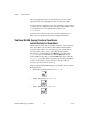
To place the GeneralDAQEvent control into your form, go to the tool
box window and select the GeneralDAQEvent tool, labelled DAQ
EVENT.
Traditional NI-DAQ (Legacy) User Manual
3-14
ni.com
Chapter 3
Software Overview
3.
Click somewhere on the form, and while holding down the mouse
button, drag the mouse to place the control onto the form. You will see
a small icon, which does not appear in run time.
4.
To set up a DAQ Event that notifies you after every n scans
(DAQ Event #1), unless you decide to make n very large, you can use
the Set_DAQ_Device_Info function to set the device analog
inputs to use interrupts. The constants used in this function
come from NIDAQCNS.INC. Refer to the function description for
Set_DAQ_Device_Info in the Traditional NI-DAQ (Legacy) C
Reference Help for more information. You also must configure some
parameters so that the GeneralDAQEvent can occur when it needs to.
In the Form_Load event routine, add the following to the existing
code:
er% = Set_DAQ_Device_Info(1, ND_DATA_XFER_MODE_AI,
ND_INTERRUPTS) set AI to use INTR
GeneralDAQEvent1.Board = 1 ‘assume Device 1
GeneralDAQEvent1.DAQEvent = 1 ‘event every N scans
GeneralDAQEvent1.DAQTrigVal0 = 1000 ‘set N=1000
scans
GeneralDAQEvent1.Enabled = True
5.
Next, start an asynchronous operation. Use the Traditional NI-DAQ
(Legacy) function DAQ_Start. Set up your program so it does a
DAQ_Start on channel 0 when you click a button you have placed on
your form. To do so, add the following code in the
Command1_Click() subroutine as follows:
Redim buffer%(10000)
GeneralDAQEvent1.ChanStr = "AI0"
GeneralDAQEvent1.Refresh ‘refresh to set params
er% = DAQ_Start(1, 0, 1, buffer%(0), 10000, 3, 10)
6.
© National Instruments Corporation
Next, define what to do when the DAQ Event occurs. In this
example, we can easily update a text box upon every 1,000 scans
and also when the whole acquisition is complete. Place a text box
on your form. It is automatically named Text 1.
3-15
Traditional NI-DAQ (Legacy) User Manual
Chapter 3
Software Overview
7.
Go to the code window, pull down on the Object combo box, and
select GeneralDAQEvent1. The only Proc for this control object is
Fire. Within the subroutine, enter the following code:
If (DoneFlag% <> 1) Then
Text1.Text = Str$(Scans&)+"scans have been
acquired."
Else
Text1.Text = "Acquisition is complete!"
er% = DAQ_Clear(1)
End If
8.
Make sure that you stop any ongoing acquisition when you stop the
program. To do so, call the DAQ_Clear function before the End
statement in the subroutine Command2_Click(_). Place another
button on your form and label it Exit. The subroutine should have
code as follows:
er% = DAQ_Clear(1)
End
9.
Run the program. Because you are not going to display the data onto a
graph, it does not matter what the data is; however, when you click the
Click Me! button, the text box should update its contents every second.
After all the scans are acquired, you should see the text box display a
completion message. If you run into errors, refer to the Traditional
NI-DAQ (Legacy) C Reference Help for guidance.
10. Click the Exit button to stop the program.
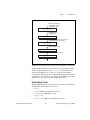
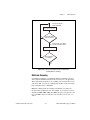
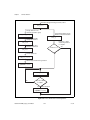
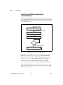
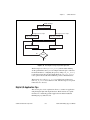
Analog Input Function Group
The analog input function group contains two sets of functions—the
one-shot analog input functions, which perform single A/D conversions,
and the data acquisition functions, which perform multiple clocked,
buffered A/D functions. Within the analog input functions, single-channel
analog input (AI) functions perform single A/D conversions on one
channel. Within the data acquisition functions, there are high-level,
low-level, and low-level double buffered functions.
If you are using SCXI analog input modules, you must use the SCXI
functions first to program the SCXI hardware. Then you can use these
functions to acquire the data using your DAQ device.
Traditional NI-DAQ (Legacy) User Manual
3-16
ni.com
Chapter 3
Software Overview
One-Shot Analog Input Functions
Single-Channel Analog Input Functions
Use the single-channel analog input functions on the MIO and AI devices.
Refer to the Traditional NI-DAQ (Legacy) C Reference Help to determine
which functions your device supports.
AI_Check
Returns the status of the analog input
circuitry and an analog input reading if
one is available. AI_Check is intended
for use when A/D conversions are
initiated by external pulses applied at the
appropriate pin; refer to DAQ_Config in
the Traditional NI-DAQ (Legacy) C
Reference Help for information on
enabling external conversions.
AI_Clear
Clears the analog input circuitry and
empties the FIFO memory.
AI_Change_Parameter
Selects a specific parameter setting for
the analog input section or analog input
channel. Use this to set the coupling for
AI channels.
AI_Configure
Informs Traditional NI-DAQ (Legacy) of
the input mode (single-ended or
differential), input range, and input
polarity selected for the device. Use this
function if you change the jumpers
affecting the analog input configuration
from their factory settings. For the
E Series devices which have no jumpers
for analog input configuration, this
function programs the device for the
settings you want. For the E Series
devices you can configure the input mode
and polarity on a per channel basis. Also
use AI_Configure to specify whether to
drive AISENSE to onboard ground.
AI_Mux_Config
Configures the number of multiplexer
(AMUX-64T) devices connected to
© National Instruments Corporation
3-17
Traditional NI-DAQ (Legacy) User Manual
Chapter 3
Software Overview
an MIO and AI device and informs
Traditional NI-DAQ (Legacy) if any
AMUX-64T devices are attached to the
system. This function applies only to the
MIO and AI devices.
AI_Read
Reads an analog input channel (initiates
an A/D conversion on an analog input
channel) and returns the unscaled result.
AI_Read_Scan
Returns readings for all analog input
channels selected by Scan_Setup.
AI_Read_VScan
Returns readings in volts for analog input
channels selected by Scan_Setup.
AI_Setup
Selects the specified analog input channel
and gain setting for externally pulsed
conversion operations.
AI_VRead
Reads an analog input channel (initiates
an A/D conversion on an analog input
channel) and returns the result scaled
to a voltage in units of volts.
AI_VScale
Converts the binary result from an
AI_Read call to the actual input voltage.
Single-Channel Analog Input Application Tips
All of the Traditional NI-DAQ (Legacy) functions described in this section
are for nonbuffered single-point analog input readings. For buffered data
acquisition, refer to the Data Acquisition Functions section.
Two of the AI functions are related to device configuration. If you
have changed the device jumper settings from the factory-default settings
or want to reprogram the E Series devices, call AI_Configure at the
beginning of your application to inform Traditional NI-DAQ (Legacy)
about the changes. Furthermore, if you have connected multiplexer devices
(AMUX-64T) to your MIO and AI devices, call AI_Mux_Config once at
the beginning of your application to inform Traditional NI-DAQ (Legacy)
about the multiplexer devices.
For most purposes, AI_VRead is the only function required to perform
single-point analog input readings. Use AI_Read when unscaled data is
sufficient or when extra time taken by AI_VRead to scale the data is
Traditional NI-DAQ (Legacy) User Manual
3-18
ni.com
Chapter 3
Software Overview
detrimental to your applications. Use AI_VScale to convert the binary
values to voltages at a later time if you want. Refer to Figure 3-1 for the
function flow typical of single-point data acquisition. Also, refer to the
NI-DAQ Examples Online Help (nidaqex.hlp) to find a related example.
When using SCXI as a front end for analog input to the MIO and AI
devices, it is not advisable to use the AI_VRead function because that
function does not take into account the gain of the SCXI module when
scaling the data. Use the AI_Read function to obtain the unscaled data,
then call the SCXI_Scale function using both the SCXI module gain and
the DAQ device gain.
Change analog input
default configuration.
AI_Configure
Add AMUX-64T
configuration.
AI_Mux_Config
Yes
Binary reading?
Retrieve an analog
reading in terms of a
binary value.
No
Retrieve an analog
reading in terms of
voltage.
AI_VRead
AI_Read
Yes
Another reading?
No
Figure 3-1. Single-Point Analog Reading with Onboard Conversion Timing
© National Instruments Corporation
3-19
Traditional NI-DAQ (Legacy) User Manual
Chapter 3
Software Overview
When accurate sample timing is important, you can use external conversion
pulses with AI_Clear, AI_Setup, and AI_Check to sample your signal
on the analog input channels. Refer to Figure 3-2 for the function flow
typical of single-point data acquisition using external conversion pulses.
However, this method works only if your computer is faster than the rate of
conversion pulses. Refer to the Data Acquisition Functions section to learn
more about interrupt and DMA-driven data acquisition by using high-speed
data acquisition.
When you are using SCXI analog input modules, use the SCXI functions
to set up the SCXI chassis and modules before using the AI functions
described in Figures 3-1 and 3-2.
Change analog input
default configuration.
AI_Configure
Add AMUX-64T
configuration.
AI_Mux_Config
Clean up onboard FIFO
memory for new conversion.
AI_Clear
Select an analog
input channel.
AI_Setup
Check for new data in
FIFO memory.
AI_Check
Yes
Another reading?
No
Figure 3-2. Single-Point Analog Reading with External Conversion Timing
Traditional NI-DAQ (Legacy) User Manual
3-20
ni.com
Chapter 3
Software Overview
Data Acquisition Functions
High-Level Data Acquisition Functions
These high-level data acquisition functions are synchronous calls that
acquire data and return when data acquisition is complete.
Refer to the Traditional NI-DAQ (Legacy) C Reference Help to determine
which functions your device supports.
DAQ_Op
Performs a synchronous, single-channel
data acquisition operation. DAQ_Op does
not return until Traditional NI-DAQ
(Legacy) has acquired all the data or an
acquisition error has occurred.
DAQ_to_Disk
Performs a synchronous, single-channel
data acquisition operation and saves the
acquired data in a disk file.
DAQ_to_Disk does not return until
Traditional (Legacy) NI-DAQ has
acquired and saved all the data or an
acquisition error has occurred.
Lab_ISCAN_Op
Performs a synchronous,
multiple-channel scanned data
acquisition operation. Lab_ISCAN_Op
does not return until Traditional NI-DAQ
(Legacy) has acquired all the data or an
acquisition error has occurred.
Lab_ISCAN_to_Disk
Performs a synchronous,
multiple-channel scanned data
acquisition operation and simultaneously
saves the acquired data in a disk file.
Lab_ISCAN_to_Disk does not return
until Traditional NI-DAQ (Legacy) has
acquired all the data and saved all the data
or an acquisition error has occurred.
SCAN_Op
Performs a synchronous,
multiple-channel scanned data
acquisition operation. SCAN_Op does not
return until Traditional NI-DAQ (Legacy)
© National Instruments Corporation
3-21
Traditional NI-DAQ (Legacy) User Manual
Chapter 3
Software Overview
has acquired all the data or an acquisition
error has occurred.
Performs a synchronous,
multiple-channel scanned data
acquisition operation and simultaneously
saves the acquired data in a disk file.
SCAN_to_Disk does not return until
Traditional NI-DAQ (Legacy) has
acquired all the data and saved it or until
an acquisition error has occurred.
SCAN_to_Disk
Low-Level Data Acquisition Functions
These functions are low-level primitives used for setting up, starting, and
monitoring asynchronous data acquisition operations.
Refer to the Traditional NI-DAQ (Legacy) C Reference Help to determine
which functions your device supports.
DAQ_Check
Checks if the current data acquisition
operation is complete and returns the
status and the number of samples
acquired to that point.
DAQ_Clear
Cancels the current data acquisition
operation (both single-channel and
multiple-channel scanned) and
reinitializes the data acquisition circuitry.
DAQ_Config
Stores configuration information for
subsequent data acquisition operations.
DAQ_Monitor
Returns data from an asynchronous
data acquisition in progress. During a
multiple-channel acquisition, you can call
DAQ_Monitor to retrieve data from a
single channel or from all channels being
scanned. Using the oldest/newest mode,
you can specify whether DAQ_Monitor
returns sequential (oldest) blocks of data,
or the most recently acquired (newest)
blocks of data.
Traditional NI-DAQ (Legacy) User Manual
3-22
ni.com
Chapter 3
Software Overview
DAQ_Rate
Converts a data acquisition rate into the
timebase and sample-interval values
needed to produce the rate you want.
DAQ_Set_Clock
Sets the scan rate for a group of channels.
DAQ_Start
Initiates an asynchronous, single-channel
data acquisition operation and stores its
input in an array.
DAQ_StopTrigger_Config
Enables the pretrigger mode of data
acquisition and indicates the number of
data points to acquire after you apply the
stop trigger pulse at the appropriate
PFI pin.
DAQ_VScale
Converts the values of an array of
acquired binary data and the gain setting
for that data to actual input voltages
measured.
Lab_ISCAN_Check
Checks if the current scan data
acquisition operation begun by the
Lab_ISCAN_Start function is complete
and returns the status, the number of
samples acquired to that point, and the
scanning order of the channels in the data
array.
Lab_ISCAN_Start
Initiates a multiple-channel scanned data
acquisition operation and stores its input
in an array.
SCAN_Demux
Rearranges, or demultiplexes, data
acquired by a SCAN operation into
row-major order (that is, each row of the
array holding the data corresponds to a
scanned channel) for easier access by
C applications. SCAN_Demux does not
need to be called by BASIC applications
to rearrange two-dimensional arrays
because these arrays are accessed in
column-major order.
© National Instruments Corporation
3-23
Traditional NI-DAQ (Legacy) User Manual
Chapter 3
Software Overview
SCAN_Sequence_Demux
Rearranges the data produced by a
multirate acquisition so that all the data
from each channel is stored in adjacent
elements of your buffer.
SCAN_Sequence_Retrieve
Returns the scan sequence created by
Traditional NI-DAQ (Legacy) as a result
of a previous call to
SCAN_Sequence_Setup.
SCAN_Sequence_Setup
Initializes the device for a multirate
scanned data acquisition operation.
Initialization includes selecting the
channels to be scanned, assigning gains to
these channels, and assigning different
sampling rates to each channel by
dividing down the base scan rate.
SCAN_Setup
Initializes circuitry for a scanned data
acquisition operation. Initialization
includes storing a table of the channel
sequence and gain setting for each
channel to be digitized.
SCAN_Start
Initiates a multiple-channel scanned data
acquisition operation, with or without
interval scanning, and stores its input in
an array.
Low-Level Double-Buffered Data Acquisition
Functions
These functions are low-level primitives used for setting up and monitoring
asynchronous double-buffered data acquisition operations.
Refer to the Traditional NI-DAQ (Legacy) C Reference Help to determine
which functions your device supports.
DAQ_DB_Config
Enables or disables double-buffered data
acquisition operations.
DAQ_DB_HalfReady
Checks if the next half buffer of data is
available during a double-buffered data
acquisition.
Traditional NI-DAQ (Legacy) User Manual
3-24
ni.com
Chapter 3
Software Overview
Transfers half of the data from the buffer
being used for double-buffered data
acquisition to another buffer, which is
passed to the function. This function
waits until the data to be transferred is
available before returning. You can
execute DAQ_DB_Transfer repeatedly
to return sequential half buffers of the
data.
DAQ_DB_Transfer
Data Acquisition Application Tips
LPM Device Counter/Timer Signals
For these devices, counter 0 produces the sample interval for data
acquisition timing. If data acquisition is not in progress, you can call the
ICTR functions to use counter 0 as a general-purpose counter. Because the
CLOCK0 input is connected to a 1 MHz oscillator, the timebase for
counter 0 is fixed.
External Multiplexer Support (AMUX-64T)
You can expand the number of analog input signals measurable by the
MIO and AI devices with an external multiplexer device (AMUX-64T).
Refer to the AMUX-64T User Manual for more information on the external
multiplexer device.
Basic Building Blocks
Most of the buffered data acquisition applications are made up of four
building blocks, as shown in Figure 3-3. However, depending on the
specific devices and applications you have, the Traditional NI-DAQ
(Legacy) functions comprising each building block vary. Typical
applications can include the Traditional NI-DAQ (Legacy) functions in
each of their four building blocks.
© National Instruments Corporation
3-25
Traditional NI-DAQ (Legacy) User Manual
Chapter 3
Software Overview
Configuration
Start
Checking
Cleaning up
Figure 3-3. Buffered Data Acquisition Basic Building Blocks
When using SCXI analog input modules, use the SCXI functions to set up
the SCXI chassis and modules before using the AI, DAQ, SCAN, and
Lab_ISCAN functions shown in the following flowcharts.
Building Block 1: Configuration
Five configuration functions are available for creating the first building
block, as shown in Figure 3-4. However, you do not have to call all five
functions every time you start a data acquisition.
Traditional NI-DAQ (Legacy) User Manual
3-26
ni.com
Chapter 3
Software Overview
Alter low-level board
configuration such as
analog input mode.
AI_Configure
Add AMUX-64T
Configuration.
AI_Mux_Config
Alter start trigger, external conversion,
and external scan clock modes.
DAQ_Config
Alter pretrigger mode.
DAQ_StopTrigger_Config
Alter double-buffered mode.
DAQ_DB_Config
Figure 3-4. Buffered Data Acquisition Application Building Block 1, Configuration
Traditional NI-DAQ (Legacy) records the device configurations and the
default configurations. Refer to the Init_DA_Brds description in the
Traditional NI-DAQ (Legacy) C Reference Help for device default
configurations. Therefore, if you are satisfied with the default or the current
configurations of your devices, your configuration building block will be
empty, and you can go on to the next building block, Start.
Building Block 2: Start
Traditional NI-DAQ (Legacy) has high-level and low-level start functions.
The high-level start functions are as follows:
•
DAQ_Op
•
SCAN_Op (MIO, AI, and DSA devices only)
•
Lab_ISCAN_Op (LPM devices only)
•
DAQ_to_Disk
•
SCAN_to_Disk (MIO, AI, and DSA devices only)
© National Instruments Corporation
3-27
Traditional NI-DAQ (Legacy) User Manual
Chapter 3
Software Overview
•
Lab_ISCAN_to_Disk (LPM devices only)
A high-level start call initiates data acquisition but does not return to the
function caller until the data acquisition is complete. For that reason, you
do not need the next building block, Checking, when you use high-level
start functions.
No
No
Yes
Streaming
to disk?
No
Yes
Scan Multiple
Channels?
Yes
Scan Multiple
Channels?
DAQ_to_Disk
DAQ_Op
No
MIO, AI or
DSA Device?
No
Yes
SCAN_Op
Lab_ISCAN_Op
MIO, AI or
DSA Device?
Lab_ISCAN_to_Disk
Yes
SCAN_to_Disk
Figure 3-5. Buffered Data Acquisition Application Building Block 2, Start
The major advantage of the high-level start functions is that they are simple.
A single call can produce a buffer full or a disk full of data. However, if
your application is acquiring data at a very slow rate or is acquiring a lot
of data, the high-level start functions might tie up the computer for a
significant amount of time. Therefore, Traditional NI-DAQ (Legacy) has
some low-level (or asynchronous) start functions that initiate data
acquisition and return to the calling program function caller immediately.
Traditional NI-DAQ (Legacy) User Manual
3-28
ni.com
Chapter 3
Software Overview
Asynchronous start functions include DAQ_Start, SCAN_Start, and
Lab_ISCAN_Start. Figures 3-6 and 3-7 show how the start calls make
up building block 2 for different devices.
Convert sampling rate to
sample timebase and
sample interval.
DAQ_Rate
Yes
Sample multiple
channels?
No
Select channels and their gain for
multiple-channel scanning.
SCAN_Setup
Initiate single-channel
data acquisition.
Initiate multiple-channel
data acquisition.
DAQ_Start
SCAN_Start
Figure 3-6. Buffered Data Acquisition Application Building Block 2, Start,
for the MIO, AI, and DSA Devices
For DSA devices, substitute DAQ_Set_Clock for DAQ_Rate in Figure 3-6.
DAQ_Rate will not produce the correct clock settings for DSA devices.
If your device works with multirate scanning, you can use
SCAN_Sequence_Setup instead of SCAN_Setup in building block 2.
© National Instruments Corporation
3-29
Traditional NI-DAQ (Legacy) User Manual
Chapter 3
Software Overview
Convert sampling rate to
sample timebase and
sample interval.
DAQ_Rate
Yes
Sample multiple
channels?
Initiate multiple-channel
data acquisition.
No
Initiate single-channel
data acquisition.
Lab_ISCAN_Start
DAQ_Start
Figure 3-7. Buffered Data Acquisition Application Building Block 2, Start,
for the LPM Devices
When you have the asynchronous start calls in your building block 2,
the next building block, Checking, is very useful for determining the
status of the ongoing data acquisition process.
Traditional NI-DAQ (Legacy) User Manual
3-30
ni.com
Chapter 3
Software Overview
Building Block 3: Checking
DAQ_Check and Lab_ISCAN_Check, shown in Figures 3-8 and 3-9, are
simple and quick ways to check the ongoing data acquisition process. This
call is often put in a while loop so that the application can periodically
monitor the data acquisition process.
Check ongoing single or
multiple-channel
data acquisition status.
DAQ_Check
No
Data Acquisition
complete?
Yes
Figure 3-8. Buffered Data Acquisition Application Building Block 3, Checking,
for the MIO, AI, and DSA Devices
Yes
Check ongoing multiplechannel data acquisition
status
Sample multiple
channels?
Lab_ISCAN_Check
No
Check ongoing singlechannel data acquisition
status
DAQ_Check
Figure 3-9. Buffered Data Acquisition Application Building Block 3, Checking,
for the LPM Devices
However, if the information provided by DAQ_Check is not sufficient,
DAQ_Monitor or the double-buffered functions might be a better choice.
With DAQ_Monitor, not only can you monitor the data acquisition
© National Instruments Corporation
3-31
Traditional NI-DAQ (Legacy) User Manual
Chapter 3
Software Overview
process, but you can also retrieve a portion of the acquired data. With the
double-buffered functions, you can retrieve half of the data buffer at a time.
Double-buffered functions are very useful when your application has a
real-time strip chart displaying the incoming data.
Building Block 4: Cleaning up
The purpose of this building block is to stop the data acquisition and
free any system resources (such as DMA channels) used for the data
acquisition. DAQ_Clear is the only function needed for this building block
and is automatically called by the check functions described in the previous
building block when the data acquisition is complete. Therefore, you can
eliminate this last building block if your application continuously calls the
previously described check functions until the data acquisition is complete.
Note
DAQ_Clear does not alter the device configurations made by building block 1.
Double-Buffered Data Acquisition
The double-buffered (DAQ_DB) data acquisition functions return data from
an ongoing data acquisition without interrupting the acquisition. These
functions use a double or circular buffering scheme that permits half
buffers of data to be retrieved and processed as the data becomes available.
By using a circular buffer, you can collect an unlimited amount of data
without needing an unlimited amount of memory. Double-buffered data
acquisition is useful for applications such as streaming data to disk and
real-time data display.
Initiating double-buffered data acquisition requires some simple changes
to the first and third basic building blocks, Configuration and Checking,
respectively.
In building block 1, turn on double-buffered mode data acquisition through
the DAQ_DB_Config call. After the double-buffered mode is enabled, all
subsequent data acquisitions are in double-buffered mode.
In building block 3, different checking functions are needed. Figure 3-10
shows a simple way to monitor the data acquisition in progress and to
retrieve data when they are available.
For further details on double-buffered data acquisition, refer to Chapter 4,
Traditional NI-DAQ (Legacy) Double Buffering.
Traditional NI-DAQ (Legacy) User Manual
3-32
ni.com
Chapter 3
Software Overview
Check for next half
buffer availability.
DAQ_DB_HalfReady
No
Next half buffer
ready for transfer?
Retrieve half of the data in
Yes the data acquisition buffer.
DAQ_DB_Transfer
No
Data acquisition
complete?
Yes
Figure 3-10. Double-Buffered Data Acquisition Application
Building Block 3, Checking
Multirate Scanning
Use multirate scanning to scan multiple channels at different scan rates
and acquire the minimum amount of data necessary for your application.
This is particularly useful if you are scanning very fast and want to write
your data to disk, or if you are acquiring large amounts of data and want to
keep your buffer size to a minimum.
Multirate scanning works by scanning each channel at a rate that is a
fraction of the specified scan rate. For example, if you want to scan four
channels at 6,000, 4,000, 3,000, and 1,000 scans per second, specify a scan
rate of 12,000 scans per second and a scan rate divisor vector of 2, 3, 4,
and 12.
© National Instruments Corporation
3-33
Traditional NI-DAQ (Legacy) User Manual
Chapter 3
Software Overview
NI-DAQ includes three functions for multirate scanning:
•
SCAN_Sequence_Setup
•
SCAN_Sequence_Retrieve
•
SCAN_Sequence_Demux
Use SCAN_Sequence_Setup to identify the channels to scan, their
gains, and their scan rate divisors. After the data is acquired, use
SCAN_Sequence_Retrieve and SCAN_Sequence_Demux to arrange
the data into a more convenient format.
Figure 3-11 shows how to use the multirate scanning functions in
conjunction with other Traditional NI-DAQ (Legacy) functions.
Traditional NI-DAQ (Legacy) User Manual
3-34
ni.com
Chapter 3
Software Overview
Convert sampling rate to sample
timebase and sample interval; convert scan
rate to scan timebase and scan interval.
DAQ_Rate
Select channels and their gains
and scan rate divisors.
SCAN_Sequence_Setup
Allocate your buffer using the values
returned by SCAN_Sequence_Setup in
the scansPerSequence and
samplesPerSequence output variables.
Retrieve the scan sequence vector
for use in the SCAN_Sequence_Demux function.
SCAN_Sequence_Retrieve
Initiate multiple-channel data acquisition.
SCAN_Start
Check ongoing data acquisition status.
DAQ_Check
No
Data acquisition
complete?
Yes
Rearrange the data in your data acquisition buffer
so that all data from each channel is stored
in adjacent elements of your buffer.
SCAN_Sequence_Demux
Add AMUX-64T
configuration.
Figure 3-11. Multirate Scanning
© National Instruments Corporation
3-35
Traditional NI-DAQ (Legacy) User Manual
Chapter 3
Software Overview
Analog Output Function Group
The Analog Output function group contains two sets of functions—the
Analog Output (AO) functions, which perform single D/A conversions, and
the Waveform (WFM) functions, which perform buffered D/A conversions.
Use the SCXI functions described later in this chapter for the SCXI-1124 analog
output module.
Note
One-Shot Analog Output Functions
Use the Analog Output functions to perform single D/A conversions with
analog output devices.
Refer to the Traditional NI-DAQ (Legacy) C Reference Help to determine
which functions your device supports.
AO_Change_Parameter
Selects a specific parameter setting
for the analog output section or analog
output channel. These parameters might
be data transfer conditions, filter settings,
or similar device settings.
AO_Configure
Records the output range and polarity
selected for each analog output channel
by the jumper settings on the device and
indicates the update mode of the DACs.
Use this function if you have changed the
jumper settings affecting analog output
range and polarity from their factory
settings. Also use this function to change
the analog output settings on devices
without jumpers.
AO_Update
Updates analog output channels on the
specified device to new voltage values
when the later internal update mode is
enabled by a previous call to
AO_Configure.
AO_VScale
Scales a voltage to a binary value that,
when written to one of the analog output
channels, produces the specified voltage.
Traditional NI-DAQ (Legacy) User Manual
3-36
ni.com
Chapter 3
Software Overview
AO_VWrite
Accepts a floating-point voltage value,
scales it to the proper binary number, and
writes that number to an analog output
channel to change the output voltage.
AO_Write
Writes a binary value to one of the analog
output channels, changing the voltage
produced at the channel.
Analog Output Application Tips
This section contains a basic explanation of how to construct an application
using the analog output functions. The flowcharts are a quick reference for
constructing potential applications from the Traditional NI-DAQ (Legacy)
function calls.
For most purposes, AO_VWrite is the only function required to generate
single analog voltages. It converts the floating-point voltage to binary and
writes the value to the device. AO_VWrite is the equivalent of a call to
AO_VScale followed by a call to AO_Write. Figure 3-12 illustrates the
equivalency.
Scale floating-point voltage to
binary value.
Scale floating-point voltage
to binary value and output
binary voltage to board.
AO_VScale
Output binary voltage to board.
AO_VWrite
AO_Write
Figure 3-12. Equivalent Analog Output Calls
The following applications are shown using AO_VWrite. However,
substituting the equivalent AO_VScale and AO_Write calls will not
change the results.
© National Instruments Corporation
3-37
Traditional NI-DAQ (Legacy) User Manual
Chapter 3
Software Overview
Simple Analog Output Application
Figure 3-13 illustrates the basic series of calls for a simple analog output
application.
Account for any changes in the
jumper settings. Enable
external update pulses?
AO_Configure
Output voltage to board.
AO_VWrite
No
Done outputting
data?
Yes
Figure 3-13. Simple Analog Output Application
The call to AO_Configure in Figure 3-13 must be made only if you have
changed the jumper settings of an MIO or AT-AO-6/10 device. You also
might call AO_Configure to enable external updating of the voltage.
When you select external update mode, voltages written to the device are
not output until you apply a pulse to pin 48 (EXTUPDATE*) on the
AT-AO-6/10 or to the selected pin on an E Series, 671X, or 673X device.
You can simultaneously change the voltages at all the analog output
channels. The final steps in Figure 3-13 form a simple loop. New voltages
are output until the data ends.
Analog Output with Software Update Application
Another application option is to enable later software updates. Like the
external update mode, voltages written to the device are not immediately
output. Instead, the device does not output the voltages until you call
AO_Update. In later software update mode, the device changes voltages
simultaneously at all the channels. Figure 3-14 illustrates a modified
version of the flowchart in Figure 3-13.
Traditional NI-DAQ (Legacy) User Manual
3-38
ni.com
Chapter 3
Software Overview
Account for changes in the
jumper settings. Enable
software voltage update.
AO_Configure
Output voltage to board.
AO_VWrite
Wait until you are ready
to output voltage.
No
Update?
Yes
Output voltage from board.
AO_Update
No
Done outputting
data?
Yes
Figure 3-14. Analog Output with Software Updates
The first modification you make is to enable later internal updates
when you call AO_Configure. The next change, which follows the
AO_VWrite step, is the decision to wait or to output the voltage. If you
want the voltage to be output, your application must call AO_Update to
write out the voltage. The rest of the flowchart is identical to Figure 3-13.
Note
Implement buffered analog output using the Waveform Generation (WFM) functions.
© National Instruments Corporation
3-39
Traditional NI-DAQ (Legacy) User Manual
Chapter 3
Software Overview
Waveform Generation Functions
Use the Waveform Generation (WFM) functions to perform buffered analog
output operations with the MIO devices, 671X devices, 673X devices, and
AT-AO-6/10 devices.
Refer to the Traditional NI-DAQ (Legacy) C Reference Help to determine
which functions your device supports.
High-Level Waveform Generation Functions
The following high-level Waveform Generation functions accomplish with
a single call tasks that require several low-level calls to accomplish:
WFM_from_Disk
Assigns a disk file to one or more analog
output channels, selects the rate and the
number of times the data in the file is to
be generated, and starts the generation.
WFM_from_Disk always waits for
completion before returning, unless you
call Timeout_Config.
WFM_Op
Assigns a waveform buffer to one or more
analog output channels, selects the rate
and the number of times the data in the
buffer is to be generated, and starts the
generation. If the number of buffer
generations is finite, WFM_Op waits for
completion before returning, unless you
call Timeout_Config.
Low-Level Waveform Generation Functions
Low-level Waveform Generation functions are for setting up, starting, and
controlling synchronous waveform generation operations:
WFM_Chan_Control
Temporarily halts or restarts waveform
generation for a single analog output
channel.
WFM_Check
Returns status information concerning a
waveform generation operation.
WFM_ClockRate
Sets an update rate and a delay rate for a
group of analog output channels.
Traditional NI-DAQ (Legacy) User Manual
3-40
ni.com
Chapter 3
Software Overview
WFM_DB_Config
Enables and disables the double-buffered
mode of waveform generation.
WFM_DB_HalfReady
Checks if the next half buffer for one or
more channels is available for new data
during a double-buffered waveform
generation operation. You can use
WFM_DB_HalfReady to avoid the
waiting period possible with the
double-buffered transfer functions.
WFM_DB_Transfer
Transfers new data into one or more
waveform buffers (selected in
WFM_Load) as waveform generation is in
progress. WFM_DB_Transfer waits until
Traditional NI-DAQ (Legacy) can
transfer the data from the buffer to the
waveform buffer.
WFM_Group_Control
Controls waveform generation for a
group of analog output channels.
WFM_Group_Setup
Assigns one or more analog output
channels to a waveform generation group.
By default, all analog output channels
for 671X, 673X, and MIO devices are in
group 1.
WFM_Load
Assigns a waveform buffer to one or more
analog output channels and indicates the
number of waveform cycles to generate.
For the 671X devices, 673X devices, and
E Series devices, this function also
enables or disables FIFO mode waveform
generation.
WFM_Rate
Converts a waveform generation update
rate into the timebase and update-interval
values needed to produce the rate you
want.
WFM_Scale
Translates an array of floating-point
values that represent voltages into an
array of binary values that produce those
voltages. The function uses the current
© National Instruments Corporation
3-41
Traditional NI-DAQ (Legacy) User Manual
Chapter 3
Software Overview
analog output configuration settings to
perform the conversions.
Sets an update rate for a group of
channels.
WFM_Set_Clock
Waveform Generation Application Tips
This section outlines a basic explanation of constructing an application
with the Waveform Generation functions. The flowcharts are a quick
reference for constructing potential applications from the Traditional
NI-DAQ (Legacy) function calls.
Basic Waveform Generation Applications
A basic waveform application outputs a series of voltages to an analog
output channel. Figure 3-15 illustrates the ordinary series of calls for a
basic waveform application.
The first step of Figure 3-15 calls WFM_Scale. The WFM_Scale function
converts floating-point voltages to integer values, thus producing the
voltages (DAC values) you want.
You have two options available for starting a waveform generation.
The first option is to call the high-level function WFM_Op. The WFM_Op
function immediately begins the waveform generation after you call it.
If the number of iterations is nonzero, WFM_Op does not return until the
waveform generation is done and all cleanup work is complete. Setting
the iterations equal to 0 signals Traditional NI-DAQ (Legacy) to place the
waveform generation in continuous double-buffered mode. In continuous
double-buffered mode, waveform generation occurs in the background, and
the WFM_Op function returns immediately to your application. Refer to the
Double-Buffered Waveform Generation Applications section for more
information.
The second option to start a waveform generation is to call the following
sequence of functions:
1.
WFM_Group_Setup to assign one or more analog output channels to a
group.
2.
WFM_Load to assign a waveform buffer to one or more analog output
channels.
3.
WFM_Rate to convert a data output rate to a timebase and an update
interval that generates the rate you want. WFM_Rate only supports
some devices. Because it does not have a device number parameter,
Traditional NI-DAQ (Legacy) User Manual
3-42
ni.com
Chapter 3
Software Overview
it cannot return an error if you use it with a non-supported device.
Refer to the Traditional NI-DAQ (Legacy) C Reference Help for
supported devices.
4.
WFM_ClockRate or WFM_Set_Clock to set the update rate. Refer to
the Traditional NI-DAQ (Legacy) C Reference Help to find out which
function supports your device.
5.
WFM_Group_Control (with operation = START) to start the
waveform generation in the background and return to your application
after the waveform generation has begun.
The next step in Figure 3-15 shows how the call to WFM_Check.
WFM_Check retrieves the current status of the waveform generation. Your
application uses this information to determine if the generation is complete
or should be stopped.
The final step is to call WFM_Group_Control (operation = CLEAR).
The CLEAR operation performs all of the necessary cleanup work after a
waveform generation. Additionally, CLEAR halts any ongoing waveform
generation.
© National Instruments Corporation
3-43
Traditional NI-DAQ (Legacy) User Manual
Chapter 3
Software Overview
Convert floating-point voltages to binary values.
WFM_Scale
Assign channels to the
waveform generation group.
Load waveform buffer, specify
iterations, and start waveform.
WFM_Group_Setup
WFM_Op
Load waveform buffer
and specify iterations.
If iterations > 0, the
waveform generation
is complete.
WFM_Load
Convert output rate to
timebase and interval.
Yes
Iterations > 0
WFM_Rate
No
Set the update rate.
WFM_ClockRate or
WFM_Set_Clock
Start background waveform generation.
WFM_Group_Control
(operation = START)
WFM_Check
Yes
Any more data
to output?
No
Clear waveform.
WFM_Group_Control
(operation = CLEAR)
Figure 3-15. Basic Waveform Generation Application
Traditional NI-DAQ (Legacy) User Manual
3-44
ni.com
Chapter 3
Software Overview
Basic Waveform Generation with Pauses
The application skeleton described in this section is nearly identical to
the basic waveform generation application skeleton. The difference is that
the description in this section includes the pause and resume operations.
Figure 3-16 illustrates the ordinary series of calls for a basic waveform
application with pauses.
The first step of Figure 3-16 calls WFM_Group_Setup. The
WFM_Group_Setup function assigns one or more analog output channels
to a group.
The second step is to assign a buffer to the analog output channels using the
calls WFM_Scale and WFM_Load. The WFM_Scale function converts
floating-point voltages to integer values that produce the voltages you want.
The WFM_Load function assigns a waveform buffer to one or more analog
output channels.
The next step is to assign an update rate to the group of channels using the
calls WFM_Rate and WFM_ClockRate. The WFM_Rate function converts a
data output rate to a timebase and an update interval that generates the rate
you want. The WFM_ClockRate function assigns a timebase, update
interval, and delay interval to a group of analog output channels.
Notice that there are restrictions for using the WFM_ClockRate function to
specify delay rate. Refer to the WFM_ClockRate function description in the
Traditional NI-DAQ (Legacy) C Reference Help for further details.
Your application is now ready to start a waveform generation. Call
WFM_Group_Control (operation = START) to start the waveform
generation in the background. WFM_Group_Control will return to your
application after the waveform generation begins.
The next step in Figure 3-16 is an application decision to pause the
waveform generation. The application uses a number of conditions for
making this decision, including status information returned by
WFM_Check.
Pause the waveform generation by calling WFM_Group_Control
(operation = PAUSE). PAUSE stops the waveform generation and maintains
the current waveform voltage at the channel output.
© National Instruments Corporation
3-45
Traditional NI-DAQ (Legacy) User Manual
Chapter 3
Software Overview
Resume the waveform generation by calling WFM_Group_Control
(operation = RESUME). RESUME restarts the waveform generation at the
data point where it was paused. The output rate and the data buffer are
unchanged.
The final step is to call WFM_Group_Control (operation = CLEAR).
CLEAR performs all the necessary cleanup work after a waveform
generation. Additionally, CLEAR halts any ongoing waveform generation.
Traditional NI-DAQ (Legacy) User Manual
3-46
ni.com
Chapter 3
Software Overview
Assign channels to waveform generation group.
WFM_Group_Setup
Convert floating-point voltages to binary values.
WFM_Scale
Load waveform buffer and specify iterations.
WFM_Load
Convert output rate to timebase and interval.
WFM_Rate
Set the update and delay rates.
WFM_ClockRate
Start background waveform generation.
WFM_Group_Control
(operation = RESUME)
Should you pause waveform generation?
Yes
Pause wave?
WFM_Group_Control
(operation = PAUSE)
No
Start waveform
generation
where it was
paused. No
Pause the
waveform generator.
Resume waveform generation?
Resume wave?
WFM_Group_Control
(operation = RESUME)
Yes
Clear waveform.
WFM_Group_Control
(operation = CLEAR)
Figure 3-16. Waveform Generation with Pauses
© National Instruments Corporation
3-47
Traditional NI-DAQ (Legacy) User Manual
Chapter 3
Software Overview
Double-Buffered Waveform Generation Applications
You also can configure waveform generation as a double-buffered
operation. Double-buffered operations can perform continuous waveform
generation with a limited amount of memory. For an explanation of double
buffering, refer to Chapter 4, Traditional NI-DAQ (Legacy) Double
Buffering. Figure 3-17 outlines the basic steps for double-buffered
waveform applications.
First, enable double buffering by calling WFM_DB_Config as shown in the
first step of Figure 3-17.
Although every step is not in the diagram, you might also call WFM_Rate
and/or WFM_Scale as described in the basic waveform application outline.
There are two ways in which your application can start waveform
generation. The first way is to call the high-level function WFM_Op.
The second way is to call the following sequence of functions—
WFM_Group_Setup (only required on the AT-AO-6/10), WFM_Load,
WFM_ClockRate, or WFM_Set_Clock, WFM_Group_Control
(operation = START). The WFM_Group_Setup function assigns one
or more analog output channels to a group. The WFM_Load function
assigns a waveform buffer to one or more analog output channels.
This buffer is called a circular buffer. The WFM_ClockRate and
WFM_Set_Clock functions assign an update rate to a group of analog
output channels. Refer to the Traditional NI-DAQ (Legacy) C Reference
Help for the function that supports your device. Calling
WFM_Group_Control (operation = START) starts the background
waveform generation. WFM_Group_Control returns to your application
after the waveform generation begins.
After the operation begins, you can perform unlimited transfers to the
circular waveform buffer. To transfer data to the circular buffer, call the
WFM_DB_Transfer function. After you call the function, Traditional
NI-DAQ (Legacy) waits until it is able to transfer the data before returning
to the application. To avoid the waiting period, you can call
WFM_DB_HalfReady to determine if the transfer can be made
immediately. If WFM_DB_HalfReady indicates Traditional NI-DAQ
(Legacy) is not ready for a transfer, your application is free to do other
processing and check the status later.
Traditional NI-DAQ (Legacy) User Manual
3-48
ni.com
Chapter 3
Software Overview
After the final transfer, you can call WFM_Check to get the current transfer
progress. Remember, Traditional NI-DAQ (Legacy) requires some time
after the final transfer to actually output the data.
The final step is to call WFM_Group_Control (operation = CLEAR).
The CLEAR operation performs all of the necessary cleanup work after
a waveform generation. Additionally, CLEAR halts any ongoing
waveform generation.
© National Instruments Corporation
3-49
Traditional NI-DAQ (Legacy) User Manual
Chapter 3
Software Overview
Enable double buffering.
WFM_DB_Config
Assign channels to waveform generation group.
WFM_Group_Setup
Load waveform buffer and specify iterations.
WFM_Load
Set the update rate.
FM_ClockRate or
WFM_Set_Clock
Start background waveform generation.
WFM_Group_Control
(operation = START)
Check if the next half buffer is ready for data.
No
WFM_DB_HalfReady
Yes
Transfer the next half of the data to
the waveform data buffer.
WFM_DB_Transfer
Do you want to transfer
more data to the waveform buffer?
Yes
Transfer?
No
Any more data to output?
Yes
WFM_Check
No
Clear the waveform.
WFM_Group_Control
(operation = CLEAR)
Figure 3-17. Double-Buffered Waveform Generation
Traditional NI-DAQ (Legacy) User Manual
3-50
ni.com
Chapter 3
Software Overview
Reference Voltages for Analog Output Devices
Table 3-4 shows the output voltages produced when you select unipolar
output polarity.
Table 3-4. Output Voltages with Unipolar Output Polarity
Value in Waveform Buffer
Device
0
4,095
AT-MIO-16XE-10, PCI-MIO-16XE-10,
PCI-MIO-16XE-50, PCI-6031E
(MIO-64XE-10), 6052E devices
0V
—
All other MIO devices
0V
65,535
Reference voltage
Reference voltage
—
Table 3-5 shows the output voltages produced when you select bipolar
output polarity.
Table 3-5. Output Voltages with Bipolar Output Polarity
Value in Waveform Buffer
Device
–2,048
2,047
AT-MIO-16XE-10,
PCI-MIO-16XE-10,
PCI-MIO-16XE-50,
PCI-6031E
(MIO-64XE-10), PCI-6110,
PCI-6111, 6052E devices
—
—
–32,768
Negative of
the reference
voltage
32,767
Reference
voltage
All other MIO devices,
671X devices
Negative of
the reference
voltage
Reference
voltage
—
—
AT-AO-6/10
Negative of
the reference
voltage
(–10 V in
default case)
Reference
voltage
(+10 V in
default case)
—
—
673X devices
—
—
© National Instruments Corporation
3-51
Negative of
the reference
voltage
Reference
voltage
Traditional NI-DAQ (Legacy) User Manual
Chapter 3
Software Overview
Note NI PCI-4451and NI PCI-4551 devices use signed, 18-bit binary data left-justified in
a 32-bit word. Their output voltage range is ±10 V.
Minimum Update Intervals
The rate at which a device can output analog data is limited by the
performance of the host computer. For waveform generation, the limitation
is in terms of minimum update intervals. The update interval is the period
of time between outputting new voltages. Therefore, the minimum update
interval specifies the smallest possible time delay between outputting new
data points. In other words, the minimum update interval specifies the
fastest rate at which a device can output data. Refer to Chapter 4,
Traditional NI-DAQ (Legacy) Double Buffering, for more information on
the minimum update intervals.
Counter Usage
NI PCI-4451 and NI PCI-4551 devices use the same counter for both
waveform generation and analog input data acquisition. Refer to the
WFM_Set_Clock function in the Traditional NI-DAQ (Legacy) C
Reference Help for an explanation of the restrictions this causes. This
counter is separate from the general-purpose counters.
The MIO, 671X, 673X, and E Series devices use dedicated counters from
the DAQ-STC chip for waveform-generation control and timing.
On the AT-AO-6/10, counter 0 produces the total update interval for
group 1 waveform generation, and counter 1 produces the total update
interval for group 2 waveform generation. However, if the total update
interval is greater than 65,535 µs for either group 1 or 2, counter 2 is used
by counter 0 (group 1) or counter 1 (group 2) to produce the total update
interval. If either group is using counter 2 to produce the sample timebase,
counter 2 is available to the other group only if the timebase is the same
as the timebase required by the Waveform Generation functions to produce
the total update interval. In this case, counter 2 produces the same timebase
for both waveform generation groups.
FIFO Lag Effect on the MIO, E Series, NI 4451 for PCI,
NI 4551 for PCI, 671X, and 673X Devices
Group 1 analog output channels use an onboard FIFO to output data values
to the DACs. Traditional NI-DAQ (Legacy) continuously writes values to
the FIFO as long as the FIFO is not full. Traditional NI-DAQ (Legacy)
transfers data values from the FIFO to the DACs at regular intervals using
an onboard or external clock. You see a lag effect for group 1 channels
Traditional NI-DAQ (Legacy) User Manual
3-52
ni.com
Chapter 3
Software Overview
because of the FIFO buffering. That is, a value written to the FIFO is not
output to the DAC until all of the data values currently in the FIFO have
been output to the DACs. This time lag is dependent upon the update rate
(specified in WFM_ClockRate). Refer to your device user manual for a
more detailed discussion of the onboard FIFO.
Three functions are affected by the FIFO lag effect—WFM_Chan_Control,
WFM_Check, and double-buffered waveform generation.
•
WFM_Chan_Control—When you execute operation = PAUSE for a
group 1 channel, the effective pause does not occur until the FIFO has
finished writing all of the data remaining in the FIFO for the specified
channel. The same is true for the RESUME operation on a group 1
channel; Traditional NI-DAQ (Legacy) cannot place data for the
specified channel into the FIFO until the FIFO is empty.
•
WFM_Check—The values returned in pointsDone and itersDone
indicate the number of points that Traditional NI-DAQ (Legacy) has
written to the FIFO for the specified channel. A time lag occurs from
the point when Traditional NI-DAQ (Legacy) writes the data to the
FIFO when Traditional NI-DAQ (Legacy) outputs the data to the DAC.
•
When you use double-buffered waveform generation with group 1,
make sure the total number of points for all of the group 1 channels
(specified in the count parameter in WFM_Load) is at least twice the
size of the FIFO. Refer to your device user manual for information on
the analog output FIFO size.
•
For 61XX devices with onboard memory, data is transferred
to the memory in blocks of 32 bytes. Therefore, when you use
double-buffered waveform generation that does not end in a 32-byte
sample boundary, the last few points will not be output.
With PCI E Series, 671X devices, and 673X devices in NI-DAQ 5.1 and
later, you can reduce or even eliminate the FIFO lag effect by specifying the
FIFO condition Traditional NI-DAQ (Legacy) uses to determine when to
put more data into the FIFO. Refer to the AO_Change_Parameter
function in Traditional NI-DAQ (Legacy) C Reference Help for details.
Externally Triggering Your Waveform Generation Operation
You can initiate a waveform generation operation from an external
trigger signal in much the same manner as for analog input. Refer to the
Select_Signal function in the Traditional NI-DAQ (Legacy) C
Reference Help.
© National Instruments Corporation
3-53
Traditional NI-DAQ (Legacy) User Manual
Chapter 3
Software Overview
Digital I/O Function Group
The Digital I/O function group contains three sets of functions—the Digital
I/O (DIG) functions, the Group Digital I/O (DIG_Block, DIG_Grp, and
DIG_SCAN) functions, and the double-buffered Digital I/O (DIG_DB)
functions. Refer to the NI-DAQ Functions Listed by Hardware Product
section of the Traditional NI-DAQ (Legacy) C Reference Help to find out
which digital functions your device supports. The SCXI functions control
the SCXI digital and relay modules.
These devices contain a number of digital I/O ports of up to eight digital
lines in width. The name port refers to a set of digital lines. Digital lines
are also referred to as bits in this text. In many instances, you control the
set of digital lines as a group for both reading and writing purposes and for
configuration purposes. For example, you can configure the port as an input
port or as an output port, which means that the set of digital lines making
up the port consist of either all input lines or all output lines.
In NI-DAQ, you refer to ports by number. Many digital I/O devices label
ports by letter. For these devices, use port number 0 for port A, port
number 1 for port B, and so on. For example, the DIO-24 contains three
ports of eight digital lines each. Ports 0, 1, and 2 are labeled PA, PB, and
PC on the DIO-24 I/O connector. The eight digital lines making up port 0,
lines 0 through 7, are labeled PA0 through PA7.
In some cases, you can combine digital I/O ports into a larger entity
called a group. On the 653X devices, for example, you can assign any of
the ports DIOA through DIOD to one of two groups. On the PCI-6115,
PCI-6120, and 673X devices, you also can create groups smaller than the
port size. For example, both the PCI-6115 and the PCI-6120 have one
digital port of eight lines, but you can configure five lines as an input group
and three lines as an output group. A group of ports are handshaked or
clocked as a unit.
Traditional NI-DAQ (Legacy) User Manual
3-54
ni.com
Chapter 3
Software Overview
The digital I/O functions can write to and read from both an entire port
and single digital lines within the port. To write to an entire port,
Traditional NI-DAQ (Legacy) writes a byte of data to the port in a specified
digital output pattern. To read from a port, Traditional NI-DAQ (Legacy)
returns a byte of data in a specified digital output pattern. The byte mapping
to the digital I/O lines is as follows.
Table 3-6. Byte Mapping to Digital I/O Lines
Bit Number
Digital I/O Line Number
7
7 Most significant bit (MSB)
6
6
5
5
4
4
3
3
2
2
1
1
0
0 Least significant bit (LSB)
In the cases where a digital I/O port has fewer than eight lines, the most
significant bits in the byte format are ignored.
You can configure most of the digital I/O ports as either input ports
or output ports. On the 653X, DSA, 671X, 673X, and E Series devices
(except for ports 2, 3, and 4 on the AT-MIO-16DE-10), you can program
lines on the same port independently as input or output lines. Some digital
I/O ports are permanently fixed as either input ports or output ports. If you
configure a port as an input port, reading that port returns the value of the
digital lines. In this case, external devices connected to and driving those
lines determine the state of the digital lines.
If no external device is driving the lines, the lines float to some
indeterminate state, and you can read them in either state 0 (digital logic
low) or state 1 (digital logic high). If you configure a port as an output port,
writing to the port sets each digital line in the port to a digital logic high or
low, depending on the data written. In this case, these digital lines can drive
an external device. Many of the digital I/O ports have read-back capability;
if you configure the port as an output port, reading the port returns the
output state of that port.
© National Instruments Corporation
3-55
Traditional NI-DAQ (Legacy) User Manual
Chapter 3
Software Overview
You can use digital I/O ports on the DIO-24, 6025E devices, DIO-96, 653X,
DIO-32F, 673X, PCI-6115, and PCI-6120 devices for handshaking and
no-handshaking modes. These two modes have the following
characteristics:
•
No-handshaking mode—This mode changes the digital value at an
output port when written to and returns a digital value from a digital
input port when read from. No handshaking signals are generated.
•
Handshaking mode—This mode is for digital I/O handshaking; that is,
a digital input port latches the data present at the input when the port
receives a handshake signal and generates a handshake pulse when the
computer writes to a digital output port. In this mode, you can read the
status of a port or a group of ports to determine whether an external
device has accepted data written to an output port or has latched data
into an input port. The handshaking mode for the PCI 6115, PCI-6120,
and 673X devices is slightly different and is more appropriately called
a clocking mode. In the clocking mode, no two-way handshaking
signals are generated. Instead, data is latched in or latched out when a
pulse from a clock signal is detected.
On the 653X, PCI-6115, PCI-6120, and 673X devices, you must assign ports to a
group before you can use handshaking mode.
Note
Process control applications, such as controlling or monitoring relays,
often use the no-handshaking mode. Communications applications, such as
transferring data between two computers, often use the handshaking mode.
DIO-24, 6025E, AT-MIO-16DE-10, and DIO-96 Device Groups
You can group together any combination of ports 0, 1, 3, 4, 6, 7, 9, and 10
on the DIO-96, ports 0 and 1 on the DIO-24, and ports 2 and 3 on the 6025E
devices and AT-MIO-16DE-10 to make up larger ports. For example,
with the DIO-96 you can program ports 0, 3, 9, and 10 to make up a 32-bit
handshaking port, or program all eight ports to make up a 64-bit
handshaking port. Refer to Digital I/O Application Tips section and the
DIG_SCAN_Setup function description of the Traditional NI-DAQ
(Legacy) C Reference Help for more details.
653X Device Groups
On the 653X devices, you can assign ports 0 through 3 (referring to ports
DIOA through DIOD) to one of two groups for handshaking. These groups
are referred to as group 1 and group 2. Group 1 uses handshake lines REQ1
and ACK1. Group 2 uses handshake lines REQ2 and ACK2. The group
Traditional NI-DAQ (Legacy) User Manual
3-56
ni.com
Chapter 3
Software Overview
senses the REQ line. An active REQ signal is an indication that the group
must perform a read or write. The group drives the ACK line. After the
group has performed a read or write, it drives the ACK line to its active
state. Refer to your device user manual for more information on the
handshaking signals.
A group can be 8, 16, or 32 bits wide. An 8-bit group can be port 0, 1, 2,
or 3. A 16-bit group can be ports 0 and 1 or ports 2 and 3. A 32-bit group
is all four ports.
After you have assigned ports to a group, the group acts as a single entity
controlling 8, 16, or 32 digital lines simultaneously. The group controls
handshaking of that port. These ports are then read from or written to
simultaneously by writing or reading 8 or 16 bits at one time from the
group.
You can configure the groups for various handshake configurations. The
configuration choices include a handshaking protocol, inverted or
non-inverted ACK and REQ lines, and a programmed transfer settling time.
Note Implement buffered digital I/O via the DIG_Block functions described in detail in
the Traditional NI-DAQ (Legacy) C Reference Help.
PCI-6115, PCI-6120, and 673X Device Groups
On the PCI-6115, PCI-6120, and 673X devices, port 0 can be broken into
two smaller groups. These groups are referred to as group 1 and group 2.
One group is configured as an input group and the other is configured as an
output group.
Because these devices only have one digital port, a group can consist of any
combination of digital lines 0–7. For example, group 1 can be configured
as an input group containing lines 0–4 and group 2 as an output group
containing lines 5–7. Alternatively, group 1 can be configured as an output
group containing lines 1, 3, 5, and 7, and group 2 as an input group
containing lines 0, 2, 4, and 6. A portion of the eight available lines can also
be configured for group operations, with the remaining unused lines
configured for immediate digital operations. However, both groups cannot
be configured for input or output at the same time.
Although a group can consist of non-contiguous lines, there is no logical
grouping of the lines, and an 8-bit value is still passed from the input
function or returned from the output function. For example, if a group is
configured for output with lines 0, 1, 2, and 4, and the group is to be written
with all ones, the hex value of 0x17 is passed to the function instead of 0xF.
© National Instruments Corporation
3-57
Traditional NI-DAQ (Legacy) User Manual
Chapter 3
Software Overview
Group operations are buffered operations only, which means immediate
digital operations are not possible with these devices using handshaking.
Because all group operations are buffered, there is no support for a status
operation indicating when an input operation has been latched to or an
output operation latched from the digital lines. Instead, group operations
are done from a buffer. In the case of digital output operations, values are
written to a buffer and latched onto the digital lines when the appropriate
edge from a clock signal is detected. For digital input operations, values are
latched from the digital lines to the buffer when the appropriate edge of the
clock signal is detected. Either a rising edge or a falling edge of the clock
signal can be specified for latching the values. The clock source can be a
timing signal used internally or generated external to the board, and it must
be routed to one of the RTSI lines.
Digital I/O Functions
The digital I/O (DIG) functions perform nonhandshaked digital line and
port I/O.
Refer to the Traditional NI-DAQ (Legacy) C Reference Help to determine
which functions your device supports.
DIG_In_Line
Returns the digital logic state of the
specified digital input line in the
specified port.
DIG_In_Prt
Returns digital input data from the
specified digital I/O port.
DIG_Line_Config
Configures the specified line on a
specified port for direction (input
or output).
DIG_Out_Line
Sets or clears the specified digital output
line in the specified digital port.
DIG_Out_Prt
Writes digital output data to the specified
digital port.
DIG_Prt_Config
Configures the specified port for direction
(input or output).
DIG_Prt_Status
Returns a status word indicating
the handshake status of the specified port.
Traditional NI-DAQ (Legacy) User Manual
3-58
ni.com
Chapter 3
Software Overview
Group Digital I/O Functions
The Group Digital I/O (DIG_Block, DIG_Grp, and DIG_SCAN) functions
perform handshaked I/O on groups of ports.
Refer to the Traditional NI-DAQ (Legacy) C Reference Help to determine
which functions your device supports.
DIG_Block_Check
Returns the number of items remaining to
be transferred after a DIG_Block_In or
DIG_Block_Out call.
DIG_Block_Clear
Halts any ongoing asynchronous transfer,
allowing another transfer to be initiated.
DIG_Block_In
Initiates an asynchronous data transfer
from the specified group to memory.
DIG_Block_Out
Initiates an asynchronous data transfer
from memory to the specified group.
DIG_Block_PG_Config
Enables or disables the pattern generation
mode of buffered digital I/O.
DIG_Grp_Config
Configures the specified group for port
assignment, direction (input or output),
and size.
DIG_Grp_Mode
Configures the specified group for
handshake signal modes.
DIG_Grp_Status
Returns a status word indicating the
handshake status of the specified group.
DIG_In_Grp
Reads digital input data from the
specified digital group.
DIG_Out_Grp
Writes digital output data to the specified
digital group.
DIG_SCAN_Setup
Configures the specified group for port
assignment, direction (input or output),
and size.
© National Instruments Corporation
3-59
Traditional NI-DAQ (Legacy) User Manual
Chapter 3
Software Overview
DIG_Trigger_Config
Enables or disables the trigger mode of
buffered digital I/O to indicate when to
start and stop the data acquisition.
Double-Buffered Digital I/O Functions
The double-buffered digital I/O (DIG_DB) functions perform
double-buffered operations during Group Digital I/O operations.
Refer to the Traditional NI-DAQ (Legacy) C Reference Help to determine
which functions your device supports.
DIG_DB_Config
Enables or disables double-buffered
digital transfer operations and sets the
double-buffered options.
DIG_DB_HalfReady
Checks whether the next half buffer of
data is available during a double-buffered
digital block operation. You can use
DIG_DB_HalfReady to avoid the
possible waiting period that can occur
because DIG_DB_Transfer waits until
the data can be transferred before
returning.
DIG_DB_Transfer
For an input operation,
DIG_DB_Transfer waits until
Traditional NI-DAQ (Legacy) can
transfer half the data from the buffer
being used for double-buffered digital
block input to another buffer, which is
passed to the function. For an output
operation, DIG_DB_Transfer waits
until Traditional NI-DAQ (Legacy) can
transfer the data from the buffer passed to
the function to the buffer being used for
double-buffered digital block output. You
can execute DIG_DB_Transfer
repeatedly to read or write sequential half
buffers of data.
Traditional NI-DAQ (Legacy) User Manual
3-60
ni.com
Chapter 3
Software Overview
Digital Change Notification Functions
The Digital Change Notification functions provide messaging for lines
and ports on the 652X devices. For other boards such as the DIO-24,
the Config_DAQ_Event_Message function handles event messaging.
DIG_Change_Message_Config
Configures 652X devices to detect rising
or falling edges on input lines and to
notify you by generating a message.
DIG_Change_Message_Control
Controls the change notification
operation of the digital input lines on
652X devices.
Digital Filtering Function
The Digital Filtering function provides signal conditioning to filter the
inputs of 652X devices.
DIG_Filter_Config
Configures filtering for the input lines on
652X devices.
Digital Change Notification Applications with
652X Devices
Digital change notification applications automatically detect changes on
input lines and notify you or your software by message. These applications
may use digital filtering to eliminate signals that may trigger unwanted
change notification. Digital filtering can be used alone to condition and
debounce input data.
Figure 3-18 illustrates the series of calls needed for change notification on
the input data. Figure 3-19 illustrates the series of calls needed for filtering
the input data without change notification. Only 652X devices can execute
change notification and filtering applications using these functions.
© National Instruments Corporation
3-61
Traditional NI-DAQ (Legacy) User Manual
Chapter 3
Software Overview
Digital Change Detection Applications
with 653X Devices
For change detection on the 653X, refer to the DIG_Block_PG_Config
function in the function reference. For message generation on the 653X and
many other devices, refer to the Config_DAQ_Event_Message function
in the function reference.
Enable filtering?
DIG_Filter_Config
Configure Change Notification
DIG_Change_Message_Config
Start Change Notification
DIG_Change_Message_Control
Stop?
No
Yes
Stop Change Notification
DIG_Change_Message_Control
Figure 3-18. Basic Digital Change Notification
To configure change notification, call DIG_Change_Message_Config.
With DIG_Change_Message_Config, you can configure individual
digital lines for rising, falling, or rising and falling edge detection. Call
DIG_Filter_Config to enable filtering on some or all of the lines.
The next step is to start change detection messaging by calling the
DIG_Change_Message_Control function with the start control code.
To stop change notification, call DIG_Change_Message_Control with
the stop control code. These steps form the basis of a basic digital change
notification application.
Traditional NI-DAQ (Legacy) User Manual
3-62
ni.com
Chapter 3
Software Overview
Enable filtering?
DIG_Filter_Config
(Optional on 652X Devices)
Configure lines for input
Configure ports for input
DIG_Line_Config
DIG_Prt_Config
DIG_In_Line
DIG_In_Prt
No
Done?
Yes
Figure 3-19. Basic Digital Filtering of Input Data Application
The first step is to call DIG_Filter_Config, which enables filtering
on the specified lines. Next, you can configure either the ports or the lines.
For the 652X devices, configuring the ports by calling DIG_Prt_Config
is optional, because the ports have fixed directions. DIG_Line_Config
is also optional because the lines within the ports have fixed directions.
The next step is to call DIG_In_Port to read data from an input port.
Call DIG_In_Line to read a bit from a line. The final step is to loop back
if more data is to be read.
Digital I/O Application Tips
This section gives a basic explanation of how to construct an application
using the digital input and output functions. The flowcharts are a quick
reference for constructing potential applications from the Traditional
NI-DAQ (Legacy) function calls.
© National Instruments Corporation
3-63
Traditional NI-DAQ (Legacy) User Manual
Chapter 3
Software Overview
Handshaking Versus No-Handshaking Digital I/O
Digital ports can output or input digital data in two ways. The first is to
immediately read or write data to or from the port. This type of digital I/O
is called no-handshaking mode. The second method is to coordinate digital
data transfers with another digital port. The second method is called digital
I/O with handshaking. With handshaking, you use dedicated transmission
lines to ensure that data on the receiving end is not overwritten with new
data before it is read from the input port.
Traditional NI-DAQ (Legacy) supports both handshaking and
no-handshaking modes. The application outlines within this section explain
the use of both modes where they apply.
Digital Port I/O Applications
Digital port I/O applications use individual digital ports to input or output
digital data. In addition, the applications input or output data points on
an individual basis.
You can configure individual port transfers for handshaking or
no-handshaking. All AT devices with digital I/O ports can
use no-handshaking digital port I/O. DIO-24, 6025E devices,
AT-MIO-16DE-10, and DIO-96 devices can also execute handshaking
digital I/O for using the port I/O functions.
Figure 3-20 illustrates the series of calls for digital port I/O applications
with handshaking. Figure 3-21 illustrates the series of calls for digital port
I/O applications without handshaking.
Traditional NI-DAQ (Legacy) User Manual
3-64
ni.com
Chapter 3
Software Overview
Configure ports for input or output.
Enable optional handshaking?
DIG_Prt_Config
Check for port ready if
handshaking is enabled.
Not Ready
DIG_Prt_Status
Ready
Input data from port.
Output data to port.
DIG_Out_Prt
DIG_In_Prt
No
Done?
Yes
Figure 3-20. Basic Port Input or Output Application with Handshaking
© National Instruments Corporation
3-65
Traditional NI-DAQ (Legacy) User Manual
Chapter 3
Software Overview
DIG_Prt_Config
Input data from port.
Output data to port.
DIG_Out_Prt
DIG_In_Prt
No
Done?
Yes
Figure 3-21. Basic Port Input or Output Application without Handshaking
The first step is to call DIG_Prt_Config, with which you configure
the individual digital ports for input or output and enable handshaking.
If handshaking is disabled, do not check the port status. If handshaking is
enabled, call DIG_PRT_Status to determine if an output port is ready to
output a new data point, or if an input port has latched new data.
The third step is to input or output the data point. Call DIG_In_Prt to read
data from an input port. Call DIG_Out_Prt to write data to an output port.
The final step is to loop back if more data is to be input or output. These
four steps form the basis of a simple digital port I/O application.
Digital Line I/O Applications
Digital line I/O applications are similar to digital port I/O applications,
except that digital line I/O applications input or output data on a bit-by-bit
basis rather than by port. The digital line I/O can only transfer data in
no-handshaking mode.
Traditional NI-DAQ (Legacy) User Manual
3-66
ni.com
Chapter 3
Software Overview
Figure 3-22 is a flowchart outlining the basic line I/O application.
TIO, DSA,
62XX, 652X,
PCI/PXI-6703/6704,
DIO 6533 (DIO-32HS),
or E Series device?
Yes
Configure lines for input
No
Configure ports for input
DIG_Line_Config
DIG_Prt_Config
DIG_In_Line
DIG_In_Prt
No
Done?
Yes
Figure 3-22. Basic Line Input or Output Application
First, configure the digital lines for input or output. You can program
653X devices, PCI-6703, PCI-6704, PXI-6703, PXI-6704, 671X, 673X,
and E Series devices on an individual line basis. To do this,
call DIG_Line_Config. You must configure all other devices on
a port-by-port basis. As a result, you must configure all lines within a port
for the same direction. Call DIG_Prt_Config to configure a port for input
or output. For the 652X devices it is not necessary to configure a port or
line since the line direction is preconfigured.
The next step is to call DIG_In_Line or DIG_Out_Line to output or input
a bit from or to the line. The final step is to loop back until NI-DAQ has
transferred all of the data.
© National Instruments Corporation
3-67
Traditional NI-DAQ (Legacy) User Manual
Chapter 3
Software Overview
Digital Group I/O Applications
Digital group I/O applications use one or more digital ports as a single
group to input or output digital information, except for the PCI-6115,
PCI-6120, and 673X devices, which can create groups smaller than the port
size for digital operations.
Figure 3-23 is a flowchart for group digital applications that handshake one
point at a time. Only the 653X devices can execute group input or output
one point at a time.
Configure groups for input or output.
DIG_Grp_Config
After handshaking mode?
DIG_Grp_Mode
Check if group is ready for transfer.
Not Ready
DIG_Grp_Status
Ready
Input data from group.
Output data to group.
DIG_Out_Grp
DIG_In_Grp
No
Done?
Yes
Figure 3-23. Simple Digital Group Input or Output Application
Traditional NI-DAQ (Legacy) User Manual
3-68
ni.com
Chapter 3
Software Overview
At the start of your application, call DIG_Grp_Config to configure
the individual digital ports as a group. After the ports are grouped, call
DIG_Grp_Mode (second step of Figure 3-23) to alter the handshaking
mode of the 653X devices. The various handshaking modes and the default
settings are explained in the DIG_Grp_Mode function description.
The next step in your application is to check if the port is ready for a transfer
(third step of Figure 3-23). To do this, call DIG_Grp_Status. If the group
status indicates it is ready, call DIG_Out_Grp or DIG_In_Grp to transfer
the data to or from the group.
The final step of the flowchart is to loop back until all of the data has been
input or output.
Digital Group Block I/O Applications
Traditional NI-DAQ (Legacy) also contains group digital I/O functions,
which operate on blocks of data. Figure 3-24 outlines the basic steps for
applications that use block I/O.
© National Instruments Corporation
3-69
Traditional NI-DAQ (Legacy) User Manual
Chapter 3
Software Overview
Configure DIO-32F, DIO 6533 (DIO-32HS),
PCI-6115, PCI-6120, and 673X device
groups for input and output.
DIG_Grp_Config
Configure DIO-24, 6025E
devices, AT-MIO-16DE-10,
or DIO-96 for input or output.
Alter handshaking mode?
DIG_Grp_Mode
(DIO-32F and DIO 6533
DIG_Scan_Setup
Enable or disable pattern generation?
DIG_Block_PG_Config
Enable or disable start and stop triggers?
DIG_Trigger_Config
(DIO 6533 only)
Start block output.
Start block input.
DIG_Block_Out
DIG_Block_In
Any more data to input or output?
Yes
DIG_Block_Check
No
Clear block operation if
DIG_Block_Check did not.
DIG_Block_Clear
Figure 3-24. Digital Block Input or Output Application
The 653X, DIO-24, 6025E devices, AT-MIO-16DE-10, and DIO-96 all can perform
group block operations. However, the DIO-24, 6025E devices, AT-MIO-16DE-10, and
DIO-96 have special wiring requirements for groups larger than one port. The wiring for
both the input and output cases for these devices is explained in the DIG_SCAN_Setup
function description. No additional wiring is necessary for the 653X devices.
Note
Traditional NI-DAQ (Legacy) User Manual
3-70
ni.com
Chapter 3
Software Overview
The first step for a group block I/O application is to call DIG_Grp_Config
or DIG_SCAN_Setup to configure individual ports as a group. Call
DIG_Grp_Config if you have a 653X, PCI-6115, PCI-6120, or 673X
device. Call DIG_SCAN_Setup for all other devices. The DIO-32F is
restricted to group sizes of two and four ports for block I/O.
If you are using a 653X device, you can alter the handshaking mode of the
group by calling DIG_Grp_Mode. For the 653X, PCI-6115, PCI-6120, and
673X, you can perform digital pattern generation by calling
DIG_Block_PG_Config, as shown in Figure 3-24. Pattern generation is
simply reading in or writing out digital data at a fixed rate. This is the digital
equivalent of analog waveform generation. To enable pattern generation,
call DIG_Block_PG_Config as shown in Figure 3-24. You cannot
handshake with pattern generation, so do not connect any handshaking
lines. Refer to the explanation of pattern generation in the Pattern
Generation I/O with 653X, PCI-6115, PCI-6120, and 673X Devices
section for more information.
The next step for your application, as illustrated in Figure 3-25, is to call
DIG_Block_In or DIG_Block_Out to start the data transfer.
After you start the operation, you can call DIG_Block_Check to get the
current progress of the transfer. If the block operation completes prior to
a DIG_Block_Check call, DIG_Block_Check automatically calls
DIG_Block_Clear, which performs cleanup work.
The final step of a digital block operation is to call DIG_Block_Clear.
DIG_Block_Clear performs the necessary cleanup work after a
digital block operation. You must call this function explicitly if
DIG_Block_Check did not already call DIG_Block_Clear.
Note DIG_Block_Clear halts any ongoing block operation. Therefore, call
DIG_Block_Clear only if you are certain the block operation has completed or
you want to stop the current operation.
© National Instruments Corporation
3-71
Traditional NI-DAQ (Legacy) User Manual
Chapter 3
Software Overview
Configure groups for input or output.
DIG_Grp_Config
Enable double buffering.
DIG_DB_Config
Start block input.
Start block output.
DIG_Block_Out
DIG_Block_In
Is Traditional NI-DAQ (Legacy)
ready to transfer?
No
DIG_DB_HalfReady
Transfer next half of the data to or
from the digital data buffer.
Yes
DAQ_DB_Transfer
Do you wish to transfer more
data to or from the digital buffer?
Yes
Transfer?
Any more data to output?
No (Output operations only).
Yes
DIG_Block_Check
Clear block operation if
No
DIG_Block_Check did not.
DIG_Block_Clear
Figure 3-25. Double-Buffered Block Operation
Traditional NI-DAQ (Legacy) User Manual
3-72
ni.com
Chapter 3
Software Overview
The first step for an application is to call DIG_Grp_Config to configure
individual ports as a group. Although the steps have been left out of the
diagram, you can alter the handshaking mode and enable pattern generation
as shown in Figure 3-24, and explained in the Digital Group Block I/O
Applications section. Next, enable double buffering by calling
DIG_DB_Config (second step of Figure 3-25). To start the digital block
input or output, call DIG_Block_In or DIG_Block_Out.
After the operation has started, you can perform unlimited transfers to or
from the circular buffer. Input operations transfer new data from the digital
buffer for storage or processing. Output operations transfer new data to the
digital buffer for output.
To transfer to or from the circular buffer, call the DIG_DB_Transfer
function. After you call the function, Traditional NI-DAQ (Legacy) waits
until it can transfer the data before returning to the application. To avoid the
waiting period, call DIG_DB_HalfReady to determine if Traditional
NI-DAQ (Legacy) can make the transfer immediately. If
DIG_DB_HalfReady indicates that Traditional NI-DAQ (Legacy) is not
ready for a transfer, your application can do other processing and check the
status later.
After the final transfer, you can call DIG_Block_Check to get the current
progress of the transfer. For example, if you are using double-buffered
output, Traditional NI-DAQ (Legacy) requires some time after the
final transfer to actually output the data. In addition, if Traditional NI-DAQ
(Legacy) completes the block operation prior to a DIG_Block_Check call,
DIG_Block_Check automatically calls DIG_Block_Clear to perform
cleanup work.
The final step of a double-buffered block operation is to call
DIG_Block_Clear, which performs the necessary cleanup work after
a digital block operation. You must explicitly call this function if
DIG_Block_Check did not already call it.
Note DIG_Block_Clear halts any ongoing block operation. Therefore,
call DIG_Block_Clear only if you are certain the block operation is complete or if
you want to stop the current operation.
© National Instruments Corporation
3-73
Traditional NI-DAQ (Legacy) User Manual
Chapter 3
Software Overview
Pattern Generation I/O with 653X, PCI-6115, PCI-6120,
and 673X Devices
Use pattern generation for clocked digital I/O when you have a group
that is written to or read from based on the output of a counter. The
DIG_Block_PG_Config function enables the pattern generation
mode of digital I/O. When pattern generation is enabled, a subsequent
DIG_Block_In or DIG_Block_Out call automatically uses this mode.
Each group for the 653X devices has its own onboard counter so that each
can simultaneously run in this mode at different rates. Use an external
counter by connecting its output to the appropriate REQ pin at the I/O
connector. For an input group, pattern generation is analogous to a
data acquisition operation, but instead of reading analog input channels,
Traditional NI-DAQ (Legacy) reads the digital ports. For an output group,
pattern generation is analogous to waveform generation, but instead of
writing voltages to the analog output channels, Traditional NI-DAQ
(Legacy) writes digital patterns to the digital ports.
The 653X, PCI-6115, PCI-6120, and 673X, use DMA to service pattern
generation. However, certain buffers require Traditional NI-DAQ (Legacy)
to reprogram the DMA controller during the pattern generation. The extra
time needed to reprogram increases the minimum request interval (thus
decreasing the maximum rate unless you use dual DMA). Refer to
Chapter 4, Traditional NI-DAQ (Legacy) Double Buffering, for more
information.
Double-Buffered I/O
With the double-buffered (DIG_DB) digital I/O functions, you can input
or output unlimited digital data without requiring unlimited memory.
Double-buffered digital I/O is useful for applications such as streaming
data to disk and sending long data streams as output to external devices.
For an explanation of double-buffering, refer to Chapter 4, Traditional
NI-DAQ (Legacy) Double Buffering.
Digital double-buffered output operations have two options. The first
option is to stop the digital block operation if old data is ever encountered.
This occurs if the DIG_DB_Transfer function calls are not keeping pace
with the data input or output rate; that is, new data is not transferred to
or from the circular buffer quickly enough. For digital input, this option
prevents the loss of incoming data. For digital output, this option prevents
erroneous data from being transferred to an external device. If the group is
Traditional NI-DAQ (Legacy) User Manual
3-74
ni.com
Chapter 3
Software Overview
configured for handshaking, an old data stop is only a pause and a call to
one of the transfer functions resumes the digital operation. If the group is
configured for pattern generation, an old data stop forces you to clear and
restart the block operation.
The second option, available only to output groups, is the ability to transfer
data that is less than half the circular buffer size to the circular buffer. This
option is useful when long digital data streams are being output, but the size
of the data stream is not evenly divisible by the size of half of the circular
buffer. This option imposes the restriction that the double-buffered digital
block output is halted when a partial block of data has been output. This
means that the data from the first call to DIG_DB_Transfer with a count
less than half the circular buffer size is the last data output by the device.
Notice, however, that enabling either of the double-buffered digital output
options causes an artificial split in the digital block buffer, requiring DMA
reprogramming at the end of each half buffer. For a group that is configured
for handshaking, such a split means that a pause in data transfer can occur
while Traditional NI-DAQ (Legacy) reprograms the DMA. For a group
configured for pattern generation, this split can cause glitches in the digital
input or output pattern (time lapses greater than the programmed period)
during DMA reprogramming. Therefore, you should enable these options
only if necessary. Both options can be enabled or disabled by the
DIG_DB_Config function.
Note
EISA chaining is disabled if partial transfers of half buffers are enabled.
Counter/Timer Function Group
The Counter/Timer function group contains the General Purpose
Counter/Timer (GPCTR) functions. These functions perform a variety of
timing I/O and counter operations such as event counting, period and
frequency measurement, and single-pulse and pulse-train generation. Refer
to your hardware user manual to find out which operations are supported
by your device.
Counter/Timer Operation for the GPCTR Functions
Figure 3-26 shows the 16-bit counters available on DSA devices supported
by GPCTR functions.
© National Instruments Corporation
3-75
Traditional NI-DAQ (Legacy) User Manual
Chapter 3
Software Overview
SOURCE
Counter
OUT
GATE
Figure 3-26. 16-bit Counter Block Diagram
Each counter has a SOURCE input, a GATE input, and an output
labeled OUT. 24-bit and 32-bit counters also have an AUX/UP_DOWN
input, as shown in Figure 3-27.
SOURCE
GATE
Counter
OUT
AUX/UP_DOWN
Figure 3-27. 24-bit and 32-bit Counter Block Diagram
When using a 24-bit or 32-bit counter for event counting, the input signals
perform the following functions:
•
SOURCE increments or decrements the counter.
•
GATE is used to indicate when to start or stop counting intervals or
when to save the counter contents in the save register.
•
AUX/UP_DOWN controls the direction of the counting. When
configured for hardware control of counting direction, the counter
counts up when AUX/UP_DOWN is high, and it counts down when
AUX/UP_DOWN is low.
Traditional NI-DAQ (Legacy) User Manual
3-76
ni.com
Chapter 3
Software Overview
When using a counter for pulse generation, the input signals perform the
following functions:
•
The counter uses SOURCE as a timebase to generate the pulse.
•
The user specifies the pulse parameters in terms of periods of the
SOURCE input.
•
GATE can serve as a trigger signal to generate a pulse after the first
active gate edge, or after each active gate edge.
The GATE input can operate in either buffered or non-buffered mode.
Buffered measurements are similar to their single measurement
counterparts. However, multiple successive measurements are made. The
result of each measurement is saved in the Hardware Save Register on each
active edge of GATE. A buffered measurement generates a data stream.
This data stream is transferred to your computer via DMA or interrupts.
The maximum transfer rates for these buffered measurements are system
dependent. Non-buffered measurements do not use a buffer. Unbuffered
data appears on the OUT output on each active edge of GATE.
General-Purpose Counter/Timer Functions
Use the General-Purpose Counter/Timer (GPCTR) functions with the
E Series, 660X, 671X, 673X, and DSA devices. Refer to the GPCTR
functions in the Traditional NI-DAQ (Legacy) C Reference Help for a
detailed description of how to use the GPCTR functions for a variety of
applications.
GPCTR_Change_Parameter
Customizes the counter operation to fit
the requirements of your application by
selecting a specific parameter setting.
GPCTR_Config_Buffer
Assigns the buffer that Traditional
NI-DAQ (Legacy) uses for a buffered
counter operation.
GPCTR_Control
Controls the operation of the
General-Purpose Counter/Timer.
GPCTR_Read_Buffer
Transfers data from the previously
assigned buffer during an asynchronous
counter operation.
© National Instruments Corporation
3-77
Traditional NI-DAQ (Legacy) User Manual
Chapter 3
Software Overview
GPCTR_Set_Application
Selects the application for which you use
the General-Purpose Counter/Timer. The
function description in the Traditional
NI-DAQ (Legacy) C Reference Help
contains many application tips.
GPCTR_Watch
Monitors the state of the General-Purpose
Counter/Timer and its operation.
General-Purpose Counter/Timer Application Tips
The General-Purpose Counter/Timer (GPCTR) functions perform a variety
of event counting, time measurement, and pulse and pulse-train generation
operations, including buffered operations. When using the GPCTR
functions, follow the generic program flow as shown in Figure 3-28.
Select Counter Application
Program Counter (Arm)
Configure Buffer (if needed)
Read Attributes or Buffer
Change Counter Attributes
Done?
No
Yes
Reset Counter
Figure 3-28. Generic Program Flow for All GPCTR Applications
To select the type of application you want to use, (for example simple event
counting, buffered event counting, period measurement, and so on) call the
GPCTR_Set_Application function with the appropriate application
parameter. If the application is buffered, configure a buffer for use during
the acquisition using the GPCTR_Config_Buffer function. Next, change
some of the counter attributes, depending on your type of application by
calling GPCTR_Change_Parameter. For example, set the counter source
Traditional NI-DAQ (Legacy) User Manual
3-78
ni.com
Chapter 3
Software Overview
to the internal 100 kHz timebase, set the initial value of the counter to 0,
or set the output mode of the counter to pulse mode. Arm the counter with
the settings you made by calling GPCTR_Control.
If you configure the counter to use a start trigger, the counter will not start
counting until it receives the start trigger signal. Otherwise, the counter
immediately begins counting. Check the status of the counters by using the
GPCTR_Watch function. If you are doing a continuous buffered operation,
read the buffer by calling GPCTR_Read_Buffer. When the operation has
completed or you want to abort the operation, reset the counter by calling
GPCTR_Control with appropriate control code.
For more about GPCTR functions, refer to the GPCTR_Set_Application
function description in the Traditional NI-DAQ (Legacy) C Reference
Help.
Clocks or Time Counters
NI-TIO based devices have built-in clocks, which are specialized time
counters that retrieve current time and timestamp one or more digital
triggers. The number of clocks available depends on the number of NI-TIO
chips on your device. Most devices have one clock per NI-TIO chip.
Like counters, clocks have gate signals that latch their current value,
or time. They can latch a single time or multiple times in a buffer using
interrupts or DMA. Unlike counters, clocks have additional hardware that
eliminates drift by synchronizing the clocks to a PPS or IRIG-B stream.
Sample Use Cases
The following cases are examples of applications that can use clocks.
Use Case #1
The user records the time of n events with software timing precision.
A user wants to record the time of an external event—for example,
when a key is pressed on a keyboard, when a data packet is received by
a CAN controller, or when a temperature is read from an AI channel.
© National Instruments Corporation
3-79
Traditional NI-DAQ (Legacy) User Manual
Chapter 3
Software Overview
The software program flow is as follows:
1.
Initialize the clock for this application.
•
Specify the synchronization signal type (none).
•
Specify the initial DHMS value (the default value of DHMS is
undefined).
2.
Read the clock value (days, hours, minutes, seconds) when the external
event happens to determine the time of the event.
3.
At the end of the operation, free up any hardware and software
resources. After powering up, the clock will run until the power to
the TIO ASIC is turned off.
Use Case #2
The user records the time of a single event on two physically distributed
data acquisition systems with hardware timing precision.
A user wants to record how a lightning strike at a power grid in city A
travels to a grid station in city B. The lightning sensors in both cities
produce a TTL pulse upon receiving the lightning bolt in city A.
Another user wants to correlate buffered analog input measurements across
distributed data acquisition systems. He connects a GPS receiver to an
NI-TIO device on each system and connects the scan clock to the gate input
of the clock. The first active edge on the scan clock on each system will
record the global time that sample was taken. The user can use the sample
rate on each system to calculate the absolute time each sample was taken,
assuming sample rates remain constant throughout the experiment.
The software program flow is as follows:
1.
Initialize the clock for this application.
•
Specify the synchronization signal source (PFI line, RTSI line).
•
Specify the synchronization method.
Traditional NI-DAQ (Legacy) User Manual
–
If source is PPS, read the current time from the GPS receiver
via a serial port and set it as the initial DHMS value of the
clock, or choose any arbitrary value. Initialization will take
about 2 seconds.
–
If source is IRIG-B, simply wait for 2 seconds after
programming the hardware. The clock will automatically
synchronize to the GPS signal.
3-80
ni.com
Chapter 3
Software Overview
•
Specify gate signal source and polarity.
•
Clock value automatically latches upon receiving the first pulse
on its gate input.
2.
Poll the armed attribute of the clock until it is disarmed (when the
external event happens). The clock is always armed in hardware, but
the software abstraction of the clock will be unarmed after it latches
the first point.
3.
Read the clock value (days, hours, minutes, seconds) to determine the
time of the external event.
4.
At the end of the operation, free up any hardware and software
resources. After powering up, the clock will run until the power to
the TIO ASIC is turned off.
RTSI Bus Trigger Functions
The Real-Time System Integration (RTSI) Bus Trigger functions connect
and disconnect signals over the RTSI bus trigger lines.
Refer to the Traditional NI-DAQ (Legacy) C Reference Help to determine
which functions your device supports.
RTSI_Clear
Disconnects all RTSI bus trigger lines
from signals on the specified device.
RTSI_Clock
Connects or disconnects the system clock
from the RTSI bus.
RTSI_Conn
Connects a device signal to the specified
RTSI bus trigger line.
RTSI_DisConn
Disconnects a device signal from the
specified RTSI bus trigger line.
Select_Signal
Connects or disconnects a device signal
to a RTSI bus trigger line.
Refer to the Traditional NI-DAQ (Legacy) C Reference Help to determine
if your device supports RTSI.
RTSI Bus
The RTSI bus is implemented via a 34-pin ribbon cable connector on
the AT, PCI E Series, PCI-DSA, 671X, and 673X devices. On PXI DAQ
and DSA devices, the RTSI bus is implemented using PXI trigger bus lines.
© National Instruments Corporation
3-81
Traditional NI-DAQ (Legacy) User Manual
Chapter 3
Software Overview
On E Series DAQ devices for FireWire, the RTSI bus is implemented with
a 15-pin mini-DSUB connector. The RTSI bus has a 7-wire trigger bus.
Each device that works with a RTSI bus interface contains a number of
useful signals that can be driven onto, or received from, the trigger lines.
Each device is equipped with a switch with which an onboard signal is
connected to any one of the RTSI bus trigger lines through software
control. By programming one device to drive a particular trigger line and
another device to receive from the same trigger line, you can hardware
connect the two devices. Use the RTSI Bus Trigger functions described in
this chapter for this type of programmable signal interconnection between
devices.
Through the RTSI bus, you can trigger one device from another device,
share clocks and signals between devices, and synchronize devices to the
same signals. The RTSI bus also can connect signals on a single device.
To specify the signals on each device that you can connect to the RTSI bus
trigger lines, each device signal is assigned a signal code number. Make all
references to that signal by using the signal code number in the RTSI bus
trigger function calls. The signal codes for each device that can use the
RTSI bus trigger lines are outlined later in this section.
Each signal listed in this chapter also has a signal direction. If a signal is
listed with a source direction, that signal can drive the trigger lines. If a
signal is listed with a receiver direction, that signal must be received from
the trigger lines. A bidirectional signal direction means that the signal can
act as either a source or a receiver, depending on the application.
E Series, DSA, 660X, 671X, and 673X RTSI Connections
For information regarding signals on the E Series, DSA, 660X, 671X, and
673X devices that you can connect to the RTSI bus, refer to the
Select_Signal function description in the Traditional NI-DAQ (Legacy)
C Reference Help.
If you have a PXI-DSA board in slot 2 (star trigger controller slot), do not drive any
signals on RTSI 6 from other modules in the chassis. You can use other RTSI lines.
Note
The signals EXTUPDATE* and EXTUPD* externally update selected
DACs. The EXTUPDATE* signal is shared with the I/O connector. For
more information about the AT-AO-6/10 signals, refer to your device user
manual.
Traditional NI-DAQ (Legacy) User Manual
3-82
ni.com
Chapter 3
Software Overview
653X RTSI Connections
The 653X devices (except for the DAQCard-653X) contain eight signals
that you can connect to the RTSI bus trigger lines. Table 3-7 shows these
signals.
The direction of each signal depends on the function you are performing.
Some signals have a different direction when you enable pattern generation
using DIG_Block_PG_Config than when you leave pattern generation
disabled. Make sure that you do not configure a signal as a RTSI receiver
when you use that signal as a device output. For example, do not configure
the 653X device to receive the REQ1 line from the RTSI bus if you are
using internal requests, or if you have made an external connection that
drives the REQ1 pin on the I/O connector.
Table 3-7. 653X RTSI Bus Signals
Signal Name
Signal Direction
(Pattern Direction)
Signal Direction
(Handshaking,
No Pattern Generation)
Signal Direction
(No Handshaking)
Signal Code
REQ1
Receiver (external
requests) or source
(internal requests)
Receiver
Receiver
0
REQ2
Receiver (external
requests) or source
(internal requests)
Receiver
Receiver
1
ACK1
Receiver
(STARTTRIG1)
Source
Source
2
ACK2
Receiver
(STARTTRIG2)
Source
Source
3
STOPTRIG1
Receiver
Unused
Receiver
4
STOPTRIG2
Receiver
Unused
Receiver
5
PCLK1
Unused
Source (internal clock) or
receiver (external clock)
Source
6
PCLK2
Unused
Source (internal clock) or
receiver (external clock)
Source
7
REQ1 and REQ2 are request signals generated internally or received from
the I/O connector. ACK1 and ACK2 are acknowledge signals used for
handshaking mode; in pattern-generation mode, they can carry start trigger
signals instead. PCLK1 and PCLK2 are the peripheral clock lines for burst
mode. STOPTRIG1 and STOPTRIG2 are used for data acquisition timing.
For more information about the 653X signals, refer to the DIO 653X User
© National Instruments Corporation
3-83
Traditional NI-DAQ (Legacy) User Manual
Chapter 3
Software Overview
Manual. Find additional explanations of the ACK1, ACK2, STOPTRIG1,
and STOPTRIG2 signals in the DIG_Trigger_Config function in the
Traditional NI-DAQ (Legacy) C Reference Help.
RTSI Bus Application Tips
This section gives a basic explanation of how to construct an application
that uses RTSI bus Traditional NI-DAQ (Legacy) functions. Use the
flowcharts as a quick reference for constructing potential applications from
the Traditional NI-DAQ (Legacy) function calls.
An application that uses the RTSI bus has three basic steps:
1.
Connect the signals from the device to the RTSI bus.
2.
Execute the work of the application.
3.
Disconnect the signals from the RTSI bus. Figure 3-29 illustrates
the normal order of RTSI function calls.
Connect clock signals on RTSI bus?
RTSI_Clock
Connect each device signal to a specified
RTSI bus trigger line. A completed signal path
requires two RTSI_Conn calls.
RTSI_Conn
Disconnect device signal
from RTSI bus.
Disconnect all device
and clock signals
from RTSI bus.
RTSI_DisConn
Disconnect clock signal
from RTSI bus.
RTSI_Clear
RTSI_Clock
Figure 3-29. Basic RTSI Application Calls
Traditional NI-DAQ (Legacy) User Manual
3-84
ni.com
Chapter 3
Software Overview
Call RTSI_Clock/RTSI_Conn to connect the signals. Each completed
signal path requires RTSI_Conn calls. The first call specifies the device
signal to transmit onto a RTSI bus trigger line. The second call specifies
the device signal that receives a RTSI bus trigger line. After the signals
are connected, you are ready to do the actual work of your application.
After you finish with the RTSI bus, disconnect the device from the bus.
To do this, call RTSI_DisConn/RTSI_Clock for each connection made.
Alternatively, call RTSI_Clear to sever all connections from your device
to the RTSI bus.
SCXI Functions
Refer to the Traditional NI-DAQ (Legacy) C Reference Help to determine
which functions your device supports.
SCXI_AO_Write
Sets the DAC channel on the SCXI-1124
module to the specified voltage or current
output value. You also can use this
function to write a binary value directly to
the DAC channel, or to translate a voltage
or current value to the corresponding
binary value.
SCXI_Cal_Constants
Calculates calibration constants for the
particular channel and range or gain using
measured voltage/binary pairs. You can
use this function with any SCXI analog
input or analog output module. The
constants can be stored and retrieved
from Traditional NI-DAQ (Legacy)
memory or the module EEPROM (if your
module has an EEPROM). The driver
uses the calibration constants to scale
analog input data more accurately when
you use the SCXI_Scale function and
output data when you use
SCXI_AO_Write.
SCXI_Calibrate
Provides a single call calibration for the
SCXI-1112, SCXI-1125, SCXI-1520,
and SCXI-1540 modules. With the
SCXI-1112 and SCXI-1125, calling this
function calibrates individual channels.
© National Instruments Corporation
3-85
Traditional NI-DAQ (Legacy) User Manual
Chapter 3
Software Overview
However, with the SCXI-1540, calling
this function calibrates every channel.
You also use this function to update the
actual onboard reference voltage value on
the SCXI-1125 EEPROM and to copy
calibration constants to the module’s
default EEPROM load area from another
EEPROM area or from Traditional
NI-DAQ (Legacy) memory.
SCXI_Calibrate_Setup
Grounds the amplifier inputs of an
SCXI-1100, SCXI-1101, SCXI-1122, or
SCXI-1141, SCXI-1142, or SCXI-1143
so that you can determine the amplifier
offset. You also can use this function
to switch a shunt resistor across your
bridge circuit to test the circuit. This
function supports shunt calibration for the
SCXI-1122 module or the SCXI-1121
module with the SCXI-1321 terminal
block. It also supports shunt calibration
for the SCXI-1520 module with the
SCXI-1314 terminal block.
SCXI_Change_Chan
Selects a new channel of a multiplexed
module that has previously been set up for
a single-channel operation using the
SCXI_Single_Chan_Setup function.
SCXI_Configure_Connection Sets the connection type parameter to
a specified type on a given channel or all
channels on the SCXI-1520 and
SCXI-1540 modules. This function also
allows programmatic control of external
synchronization.
SCXI_Configure_Filter
Sets the specified channel to the assigned
filter setting on any SCXI module with
programmable filter settings.
SCXI_Get_Chassis_Info
Returns chassis configuration
information.
SCXI_Get_Module_Info
Returns configuration information for the
assigned SCXI chassis slot number.
Traditional NI-DAQ (Legacy) User Manual
3-86
ni.com
Chapter 3
Software Overview
SCXI_Get_State
Gets the state of a single channel or an
entire port on any digital or relay module.
SCXI_Get_Status
Reads the data in the status register on the
specified module. You can use
this function with the SCXI-1160 or
SCXI-1122 to determine if the relays
have finished switching, with the
SCXI-1124 to determine if the DACs
have settled, with the SCXI-1126 to
determine if the module has settled after
changing any of its programmable
functions (ranges, filter settings,
threshold, or hysteresis), or with the
SCXI-1102/B/C to determine if the
module has settled after changing gains.
SCXI_Load_Config
Loads the SCXI chassis configuration
information that you established in MAX.
Sets the software states of the chassis and
modules present to their default states. No
changes are made to the hardware states
of the SCXI chassis or modules.
SCXI_ModuleID_Read
Reads the Module ID register of
the SCXI module in a given slot.
The principal difference
between this function and
SCXI_Get_Module_Info is
that SCXI_ModuleID_Read does
a hardware read of the module. You
can use this function to verify that
your SCXI system is configured
and communicating properly.
SCXI_MuxCtr_Setup
Enables or disables a DAQ device counter
to be used as a multiplexer counter during
SCXI channel scanning to synchronize
the scan list with the module scan list that
Traditional NI-DAQ (Legacy) has
downloaded to Slot 0 of the SCXI chassis.
© National Instruments Corporation
3-87
Traditional NI-DAQ (Legacy) User Manual
Chapter 3
Software Overview
SCXI_Reset
Resets the specified module to its default
state. You also can use SCXI_Reset to
reset the Slot 0 scanning circuitry or to
reset the entire chassis.
SCXI_Scale
Scales an array of binary data acquired
from an SCXI channel to voltage.
SCXI_SCAN_Setup
Sets up the SCXI chassis for a
multiplexed scanning data acquisition
operation that the assigned DAQ device
will perform. The function downloads
a module scan list to Slot 0 that
determines the sequence of scanned
modules and how many channels on each
module are scanned. This function can
program each module with its given start
channel, as well as resolve any contention
on the SCXIbus.
SCXI_Set_Config
Changes the configuration of the
SCXI chassis that you established in
MAX. Sets the software states of the
chassis and modules specified to their
default states. Does not change the SCXI
chassis or module hardware states.
SCXI_Set_Excitation
Sets a specified excitation parameter to a
supplied value on a given channel or all
channels on the SCXI-1520, SCXI-1530,
SCXI-1531, and SCXI-1540 modules.
SCXI_Set_Gain
Sets the specified channel to the given
gain or range setting on any SCXI module
that works with programmable gain or
range settings.
SCXI_Set_Input_Mode
Configures the SCXI-1122 for
differential mode or 4-wire mode.
SCXI_Set_State
Sets the state of a single channel or
an entire port on any digital or relay
module.
Traditional NI-DAQ (Legacy) User Manual
3-88
ni.com
Chapter 3
Software Overview
SCXI_Set_Threshold
Used to set the high and low threshold
values for the SCXI-1126
frequency-to-voltage module.
SCXI_Single_Chan_Setup
Sets up a multiplexed module for a
single-channel analog-input operation to
be performed by the given DAQ device.
Sets the module channel, enables the
module output, and routes the module
output on the SCXIbus, if necessary.
Resolves any contention on the SCXIbus
by disabling the output of any module that
was previously driving the SCXIbus. You
also can use this function to set up to read
the temperature sensor on a terminal
block connected to the front connector of
the module.
SCXI_Strain_Null
Nulls the offset in the specified strain
gage on an SCXI-1520 strain gage
module by adjusting the internal
potentiometers.
SCXI_Track_Hold_Control Controls the track-and-hold modules
track/hold state that you set up for a
single-channel operation.
SCXI_Track_Hold_Setup
© National Instruments Corporation
3-89
Establishes the track/hold behavior of a
track-and-hold module and sets up the
module for either a single-channel or
an interval-scanning operation.
Traditional NI-DAQ (Legacy) User Manual
Chapter 3
Software Overview
SCXI Application Tips
There are three categories of SCXI applications—analog input
applications, analog output applications, and digital applications.
Figure 3-30 shows the basic structure of an SCXI application.
Load SCXI configuration that was entered in the
MAX and initialize software defaults.
SCXI_Load_Config
Reset the chassis and modules to
their default hardware settings.
SCXI_Reset
Analog Input Operations
Analog Output Operations
No
Digital Operations
Done?
Yes
Reset the chassis and modules to
their default hardware settings.
SCXI_Reset
Figure 3-30. General SCXIbus Application
The figures in the following sections show the detailed call sequences
for different types of SCXI operations. In effect, each of the remaining
flowcharts in this section is an enlargement of the Analog Input Operations,
the Analog Output Operations, or the Digital Operations node in
Figure 3-30. Refer to the function descriptions in the Traditional NI-DAQ
(Legacy) C Reference Help for detailed information about each function
used in the flowcharts.
Traditional NI-DAQ (Legacy) User Manual
3-90
ni.com
Chapter 3
Software Overview
You can divide the SCXI analog input applications further into two
categories—single-channel applications and channel-scanning
applications. The distinction between the two categories is simple—
single-channel applications do not involve automatic channel switching
by the hardware during an analog input process; channel-scanning
applications do.
After you have set up the SCXI system, single-channel applications use
the AI or the DAQ class of functions described earlier in this chapter to
acquire the input data. To acquire data from more than one channel, you
need multiple AI or DAQ function calls, and you might need explicit SCXI
function calls to change the selected SCXI channel. This specific type of
single-channel application is called software scanning.
After you have set up the SCXI system, channel-scanning applications use
the SCAN and Lab_ISCAN classes of functions described earlier in this
chapter to acquire the input data.
Building Analog Input Applications in
Multiplexed Mode
Multiplexed applications require the use of SCXI functions to select
the multiplexed channels, select the programmable module features,
route signals on the SCXIbus, and program Slot 0. After you have set
up the SCXI chassis and modules, you can use the AI, DAQ, SCAN, and
Lab_ISCAN functions to acquire the data either with a plug-in DAQ device.
The channel parameter that is passed to each of these functions is almost
always 0 because the multiplexed output of a module is connected by
default to analog input channel 0 of the DAQ device. If you are using a
PXI DAQ device with an internal connection to the PXI-1010 or PXI-1011
SCXIbus, then ND_PXI_SC is the channel parameter. When you use
multiple chassis, the modules in each chassis are multiplexed to a separate
analog input channel. In that case, the channel parameters of the AI, DAQ,
SCAN, and Lab_ISCAN functions should be the DAQ device channel that
corresponds to the chassis you want for the operation.
© National Instruments Corporation
3-91
Traditional NI-DAQ (Legacy) User Manual
Chapter 3
Software Overview
Figure 3-31 shows the function call sequence of a single-channel or
software-scanning application using an SCXI-1100, SCXI-1101,
SCXI-1102/B/C, SCXI-1104/C, SCXI-1112, SCXI-1120/D, SCXI-1121,
SCXI-1122, SCXI-1125, SCXI-1126, SCXI-1141, SCXI-1142,
SCXI-1143, SCXI-1520, SCXI-1530, SCXI-1531, or SCXI-1540 module
operating in multiplexed mode.
Set up the chassis for a single-channel
analog input operation on a specified
channel on a specified module.
SCXI_Single_Chan_Setup
If the desired module has programmable
gain and the current module gain setting is
not desirable, change to the desired gain.
SCXI_Set_Gain
Single Analog Input
Acquire data from the
desired channel on the
module using the AI
functions or the DAQ
functions.
Single-Channel Data Acquisition
If desired,change the selected
channel on the module.
SCXI_Change_Chan
Have you acquired all the data you
need from this module?
No
Done?
Yes
Figure 3-31. Single-Channel or Software-Scanning Operation in Multiplexed Mode
The SCXI_Single_Chan_Setup function selects the given channel
to appear at the module output. If the given module is not directly cabled to
the DAQ device, the function sends the module output on the SCXIbus, and
then configures the module that is cabled to the DAQ device to send the
signal present on the SCXIbus to the DAQ device.
Traditional NI-DAQ (Legacy) User Manual
3-92
ni.com
Chapter 3
Software Overview
The SCXI_Set_Gain function changes the gain or range of the
SCXI-1100, SCXI-1102/B/C, SCXI-1122, SCXI-1125, SCXI-1126,
SCXI-1141, SCXI-1142, SCXI-1143, SCXI-1520, SCXI-1530,
SCXI-1531, or SCXI-1540 module. The module maintains this gain or
range setting until you call the function again to change it. You also can
do any other module-specific programming at this point, such as
SCXI_Configure_Filter or SCXI_Set_Input_Mode.
To achieve software scanning, select a different channel on the module
using the SCXI_Change_Chan function after acquiring data from the
channel you want with the AI or DAQ functions. If you want a channel on
a different module, call the SCXI_Single_Chan_Setup function again
to enable the appropriate module outputs and manage the SCXIbus signal
routing.
Figure 3-32 shows the function call sequence of a single channel or
software-scanning application using a Simultaneous Sample and Hold
(SSH) module in multiplexed mode.
© National Instruments Corporation
3-93
Traditional NI-DAQ (Legacy) User Manual
Chapter 3
Software Overview
Configure the desired module
for a single-channel operation.
SCXI_Track_Hold_Setup
Set up the chassis for a single-channel
analog input operation on a specified channel
on a specified module.
SCXI_Single_Chan_Setup
Latch the analog inputs by
putting the module into Hold mode.
SCXI_Track_Hold_Control
Acquire data from the desired channel on
the module using the AI functions.
Single Analog Input
SCXI_Change_Chan
SCXI_Change_Chan
If desired, change the
selected channel on
the module.
Do you wish
to take more
data while the
module is in
Hold mode?
Maintain
Hold mode?
No
If desired, change the
selected channel on
the module.
Yes
Put the module back into Track mode
to sense the new input values.
SCXI_Track_Hold_Setup
Have you acquired all the data
you need from this module?
No
Done?
Yes
Figure 3-32. Single-Channel or Software-Scanning Operation Using
a Simultaneous Sample and Hold Module in Multiplexed Mode
Traditional NI-DAQ (Legacy) User Manual
3-94
ni.com
Chapter 3
Software Overview
Notice the similarities between Figure 3-32 and Figure 3-33,
which shows the corresponding application in parallel mode. The
SCXI_Track_Hold_Setup calls and the SCXI_Track_Hold_Control
calls are the same. In multiplexed mode, however, an
SCXI_Single_Chan_Setup call is required to select the
multiplexed channel and appropriately route the output to the DAQ device.
The SCXI_Change_Chan call can change the channel on the module either
while the module is in hold mode or after the module has been returned to
track mode.
Figure 3-33 shows the function call sequence of a channel-scanning
application in multiplexed mode. Remember that only the MIO and
AI devices work with channel scanning in multiplexed mode. You can use
any combination of module types in a scanning operation. If any
track-and-hold modules are to be scanned, use interval scanning; if you are
using a plug-in DAQ device, the module directly connected to the DAQ
device must be one of the SSH modules.
© National Instruments Corporation
3-95
Traditional NI-DAQ (Legacy) User Manual
Chapter 3
Software Overview
Configure each SSH Module in the
module scan list for interval scanning.
SCXI_Track_Hold_Setup
Specify the module scan list, the start channel of each module,
and the number of channels to scan on each module.
SCXI_SCAN_Setup
Set the gain and/or filter settings of each SCXI-1100, SCXI-1102/B/C,
SCXI-1122, SCXI-1125, SCXI-1141, SCXI-1142, SCXI-1143, or
SCXI-1540 module in the module scan list.
SCXI_Set_Gain and/or
SCXI-Configure_Filter
Set up the Mux Counter on the DAQ device so that the total number
of samples to be taken in one scan on the DAQ device is equal to
the total number of channels in one scan of the module scan list.
SCXI_MuxCtr_Setup
Acquire the data using the SCAN or Lab_ISCAN functions.
Remember, if there are any SSH modules to be scanned,
you must use interval scanning.
Scanned Data Acquisition
Have you acquired all the data you need?
No
Done?
Yes
Disable the Track/Hold setup of the SSH modules
to free the counter resource on the DAQ device.
SCXI_Track_Hold_Setup
Figure 3-33. Channel-Scanning Operation Using Modules in Multiplexed Mode
If any of the modules to be scanned are SSH modules, you must establish
the Track/Hold setup of each one. To synchronize multiple SSH modules,
you can configure the module that is receiving the Track/Hold control
Traditional NI-DAQ (Legacy) User Manual
3-96
ni.com
Chapter 3
Software Overview
signal to send the Track/Hold signal on the SCXIbus so that any other SSH
module can use it. The Track/Hold signal can be from either the DAQ
device counter or an external source.
The SCXI_SCAN_Setup call establishes the module scan list, which
Traditional NI-DAQ (Legacy) downloads to Slot 0. Each module is
programmed for automatic scanning starting at its given start channel. If
you need the SCXIbus during the scan to route the outputs of multiple
modules, this function resolves any contention.
In many of the data acquisition function descriptions in the Traditional
NI-DAQ (Legacy) C Reference Help, the count parameter descriptions
specify that count must be an integer multiple of the total number of
channels scanned. In channel-scanning acquisitions in multiplexed mode,
the total number of channels scanned is the sum of all the elements in the
numChans array in the SCXI_SCAN_Setup function call.
If any of the modules in the module scan list are SCXI-1100,
SCXI-1102/B/C, SCXI-1122, SCXI-1125, SCXI-1126, SCXI-1141,
SCXI-1142, SCXI-1143, SCXI-1520, SCXI-1530, SCXI-1531, or
SCXI-1540 modules, you can use SCXI_Set_Gain to change the gain or
range setting on each module. You also can use the
SCXI_Configure_Filter function for the SCXI-1122, SCXI-1125,
SCXI-1126, SCXI-1141, SCXI-1142, SCXI-1143, SCXI-1530, and
SCXI-1531, and the SCXI_Set_Input_Mode function for the SCXI-1122.
The SCXI_MuxCtr_Setup call synchronizes the module scan list with the
DAQ device scan list. In most cases (especially when using interval
scanning), it is best to ensure that the number of samples Traditional
NI-DAQ (Legacy) takes in one pass through the module scan list is the
same as the number of samples Traditional NI-DAQ (Legacy) takes in one
pass through the DAQ device scan list. Refer to the SCXI_MuxCtr_Setup
function description in the Traditional NI-DAQ (Legacy) C Reference
Help.
After you have set up the SCXI chassis and modules, you can perform more
than one channel-scanning operation using the SCAN or Lab_ISCAN
functions without reconfiguring the SCXI chassis or modules.
Building Analog Input Applications in Parallel Mode
When you operate the SCXI-1120/D, SCXI-1121, SCXI-1125,
SCXI-1126, SCXI-1141, SCXI-1142, and SCXI-1143 modules in parallel
mode, you need no further SCXI function calls beyond those shown in
Figure 3-34 to set up the modules for analog input operations. After you
© National Instruments Corporation
3-97
Traditional NI-DAQ (Legacy) User Manual
Chapter 3
Software Overview
have initialized and reset the SCXI chassis and modules, you can use the
AI, DAQ, SCAN, or Lab_ISCAN functions with the DAQ device. Remember
that the channel and gain parameters of the AI, DAQ, SCAN, and
Lab_ISCAN functions refer to the DAQ device channels and gains.
For example, to acquire a single reading from channel 0 on the module,
call the AI_Read function with the channel parameter set to 0. The
gain parameter refers to the DAQ device gain. You then can use the
SCXI_Scale function to convert the binary reading to a voltage. The
AI_VRead function call is not generally useful in SCXI applications
because it does not take into account the gain applied at the SCXI module
when scaling the binary reading.
To build a channel-scanning application using the SCXI-1120/D,
SCXI-1121, SCXI-1125, SCXI-1126, SCXI-1141, SCXI-1142, or
SCXI-1143 in parallel mode, use the SCAN and Lab_ISCAN functions to
scan the channels on the DAQ device that correspond to channels on the
module you want. For example, to scan channels 0, 1, and 3 on the module
using an MIO-16 device, call the SCAN_Op function with the channel
vector set to {0, 1, 3}. The gain vector should contain the MIO and
AI device channel gains. After the data is acquired, you can demultiplex
it and send the data for each channel to the DAQ_VScale function.
Remember to pass the total gain to the DAQ_VScale function to obtain
the voltage read at the module input.
In many of the data acquisition function descriptions in the Traditional
NI-DAQ (Legacy) C Reference Help, the count parameter descriptions
specify that count must be an integer multiple of the total number of
channels scanned. In channel-scanning acquisitions in parallel mode,
the total number of channels scanned is the numChans parameter in
the SCAN_Setup, SCAN_Op, SCAN_to_Disk, Lab_ISCAN_Start,
Lab_ISCAN_Op, or Lab_ISCAN_to_Disk function calls.
The SCXI-1100, SCXI-1101, SCXI-1102/B/C, SCXI-1104/C, SCXI-1112,
SCXI-1122, and SCXI-1540 operate in multiplexed mode only.
The SCXI-1140, SCXI-1520, SCXI-1530, and SCXI-1531 modules
require the use of SCXI functions to configure and control the Track/Hold
state of the module before you can use the AI, DAQ, SCAN, and Lab_ISCAN
functions to acquire the data. Figure 3-34 shows the function call sequence
of a single-channel (or software-scanning) operation using these modules
in parallel mode.
Traditional NI-DAQ (Legacy) User Manual
3-98
ni.com
Chapter 3
Software Overview
Configure the desired module
for a single-channel operation.
SCXI_Track_Hold_Setup
Latch the analog inputs by
putting the module into Hold mode.
SCXI_Track_Hold_Control
Acquire data from the desired channel on
the module using the AI functions.
Single Analog Input
Do you wish to take more data while
the module is in Hold mode?
Maintain
Hold mode?
No
Yes
Put the module back into Track mode
to sense the new input values.
SCXI_Track_Hold_Control
Have you acquired all the data
you need from this module?
No
Done?
Yes
Disable the Track/Hold setup of the module to free
the counter resource on the data acquisition device.
SCXI_Track_Hold_Setup
Figure 3-34. Single-Channel or Software-Scanning Operation Using an SSH Module
in Parallel Mode
The initial SCXI_Track_Hold_Setup call signals the driver that the
module is used in a single-channel application, and puts the module into
track mode. The first SCXI_Track_Hold_Control call latches, or
samples, all the module inputs; subsequent AI calls read the sampled
© National Instruments Corporation
3-99
Traditional NI-DAQ (Legacy) User Manual
Chapter 3
Software Overview
voltages. It is important to realize that all AI operations that occur between
the first SCXI_Track_Hold_Control call, which puts the module into
hold mode, and the second control call, which puts the module into track
mode, acquire data that was sampled at the time of the first control call.
One or more channels can be read while the module is in hold mode.
After you put the module back into track mode, you can repeat the
process to acquire new data.
Remember that the channel and gain parameters of the AI function
calls refer to the DAQ device channels and gains. Use the data acquisition
channels that correspond to the module channels you want, as described
earlier in this section.
Figure 3-35 shows the function call sequence of a channel-scanning
application using an SSH module in parallel mode.
Configure the desired module for
interval scanning.
SCXI_Track_Hold_Setup
Acquire data from the desired channels using interval
scanning with the SCAN and Lab_ISCAN functions.
Scanned Data Acquisition
Have you acquired all the data you need?
No
Done?
Yes
Disable the Track/Hold setup of the module to free the
counter resource on the data acquisition board.
SCXI_Track_Hold_Setup
Figure 3-35. Channel-Scanning Operation Using an SSH Module in Parallel Mode
Traditional NI-DAQ (Legacy) User Manual
3-100
ni.com
Chapter 3
Software Overview
The call sequence is much simpler because the scan interval timer
automatically controls the Track/Hold state of the module during the
interval-scanning operation. Remember that only the MIO and AI devices
work with channel-scanning using an SSH module.
SCXI Data Acquisition Rates
The settling time of the SCXI modules can affect the maximum data
acquisition rates that your DAQ device can achieve. The settling times of
the different SCXI modules at each gain setting are listed in Table 3-8 for
three different DAQ devices.
The maximum data acquisition rate you can use will be the inverse of the
settling time for your SCXI module and DAQ device. For example, if the
settling time is listed as 7 µs, your maximum data acquisition rate will be
1 - = 143 kS/s
---------7 µs
If you are using a DAQ device with a maximum acquisition rate faster
than the AT-MIO-16E-2 (such as the PCI-MIO-16E-1), you should use the
settling times and corresponding maximum acquisition rates listed for the
AT-MIO-16E-2.
If you are using a DAQ device with a maximum acquisition rate slower than
200 kS/s (such as the PCI-6032E), you should add 1 µs to the settling time
of your DAQ device. The maximum acquisition rate for the PCI-6032E
would be
1
------------------------------------ = 90.9 kS/s
( 10 µs + 1 µs )
If you are using a DAQ device faster than 200 kS/s but slower than the
AT-MIO-16E-2 (such as an AT-MIO-64E-3), you can interpolate between
the settling times listed for these devices to calculate an appropriate settling
time and corresponding maximum data acquisition rate.
© National Instruments Corporation
3-101
Traditional NI-DAQ (Legacy) User Manual
Chapter 3
Software Overview
Table 3-8. Maximum SCXI Module Settling Times
Settling Time
Using
AT-MIO-16E-22
Settling Time
Using
AT-MIO-16XE-10
(±0.006%
Accuracy)3
Settling Time
Using
AT-MIO-16XE-10
(±0.0015%
Accuracy) 3
7 µs
4 µs
10 µs
32 µs
200
10 µs
5.5 µs
10 µs
33 µs
500
16 µs
12 µs
25 µs
40 µs
1,000
50 µs
20 µs
30 µs
76 µs
2,000
50 µs
25 µs
30 µs
195 µs
SCXI-1102/B/C,
SCXI-1104/C,
SCXI-1112
all gains
7 µs
3 µs
10 µs
—
SCXI-1120,
SCXI-1120D,
SCXI-1125
all gains
7 µs
3 µs
10 µs
20 µs
SCXI-1121
all gains
7 µs
3 µs
10 µs
20 µs
SCXI-1122
all gains
10 ms
10 ms
10 ms
10 ms
SCXI-1126
all gains
or ranges
7 µs
3 µs
10 µs
20 µs
SCXI-1140
all gains
7 µs
3 µs
10 µs
20 µs
SCXI-1141,
SCXI-1142,
SCXI-1143,
SCXI-1520,
SCXI-1540
all gains
7 µs
3 µs
10 µs
20 µs
SCXI Module
SCXI-1100
(no filter)
Gain
Settling Time
Using up to
12-bit, 200 kS/s 1
Device
1 to 100
1
Includes effects of a 12-bit, 200 kS/s device with 1 m SCXI cable assembly.
2
Includes effects of AT-MIO-16E-2 with 1 or 2 m SCXI cable assembly.
3
Includes effects of AT-MIO-16XE-10 with 1 or 2 m SCXI cable assembly.
Note: If you are using remote SCXI, the maximum data acquisition rate also depends on the serial baud rate used.
For more information, refer to your SCXI user manual.
The filter setting on the SCXI-1100 and the SCXI-1122 dramatically
affects settling time. Refer to the Specifications appendix in your SCXI
module user manual for details.
Traditional NI-DAQ (Legacy) User Manual
3-102
ni.com
Chapter 3
Software Overview
The SCXI-1122 uses relays to switch the input channels. The module requires 10 ms
to settle when the relays switch, so the sampling rate in a channel scanning operation
cannot exceed 100 Hz. If you want to take many readings from each channel and average
them to reduce noise, you should use the single-channel or software-scanning method
shown in Figure 3-34 instead of the channel-scanning method shown in Figure 3-35.
Note
This means you select one channel on the module, acquire many samples on that channel
using the DAQ functions, select the next channel, and so on. This increases the lifetime of
your module relays. When you have selected a particular channel, you can use the fastest
sample rate your DAQ device supports with the DAQ functions.
Analog Output Applications
Using the SCXI-1124 analog output module with the Traditional NI-DAQ
(Legacy) functions is simple. Call the SCXI_AO_Write function to write
the voltages you want to the module DAC channels. You can use the
SCXI_Get_Status function to determine when the DAC channels have
settled to their final analog output voltages.
To calculate new calibration constants for SCXI_AO_Write to use for the
voltage to binary conversion instead of the factory calibration constants that
are shipped in the module EEPROM, refer to the SCXI_Cal_Constants
function description.
Digital Applications
If you configured your digital or relay modules for multiplexed mode,
use the SCXI_Set_State and SCXI_Get_State functions to access
your digital or relay channels.
If you are using the SCXI-1160 module, you might want to use the
SCXI_Get_Status function after calling the SCXI_Set_State function.
SCXI_Get_Status tells you when the SCXI-1160 relays have finished
switching.
If you are using the SCXI-1162/HV module, SCXI_Get_State reads
the module input channels. For the other digital and relay modules,
SCXI_Get_State returns a software copy of the current state that
Traditional NI-DAQ (Legacy) maintains. However, if you are using the
SCXI-1163/R in parallel mode, SCXI_Get_State reads the hardware
states.
© National Instruments Corporation
3-103
Traditional NI-DAQ (Legacy) User Manual
Chapter 3
Software Overview
If you are using the SCXI-1162/HV or SCXI-1163/R in parallel mode,
you can use the SCXI functions as described above, or you can call the
DIG_In_Prt and DIG_Out_Prt functions using the correct DAQ device
port numbers that correspond to the SCXI module channels. The MIO and
AI devices cannot use the SCXI-1162/HV or the SCXI-1163/R in parallel
mode.
Traditional NI-DAQ (Legacy) User Manual
3-104
ni.com
4
Traditional NI-DAQ (Legacy)
Double Buffering
This chapter describes using double-buffered data acquisitions with
Traditional NI-DAQ (Legacy). This chapter applies to counter operations;
however, you can read samples of any size.
Overview
Conventional data acquisition software techniques, such as single-buffered
data acquisition, work well for most applications. However, more
sophisticated applications involving larger amounts of data at higher
rates require more advanced techniques for managing the data. One such
technique is double buffering. National Instruments uses double-buffering
techniques in its driver software for continuous, uninterrupted input or
output of large amounts of data.
This chapter discusses the fundamentals of double buffering, including
specific information on how the Traditional NI-DAQ (Legacy)
double-buffered functions work.
Note
Input and output refer to both digital and analog operations in this chapter.
Single-Buffered versus Double-Buffered Data
The most common method of data buffering found in conventional driver
software is single buffering. In single-buffered input operations, a fixed
number of samples are acquired at a specified rate and transferred into
computer memory. After the memory buffer stores the data, the computer
can analyze, display, or store the data to the hard disk for later processing.
Single-buffered output operations output a fixed number of samples from
computer memory at a specified rate. After outputting data, the buffer
can be updated with new or freed data.
Single-buffered operations are relatively simple to implement, can usually
take advantage of the full hardware speed of the DAQ device, and are very
© National Instruments Corporation
4-1
Traditional NI-DAQ (Legacy) User Manual
Chapter 4
Traditional NI-DAQ (Legacy) Double Buffering
useful for many applications. The major disadvantage of single-buffered
operations is that the amount of data that can be input or output is limited
to the amount of free memory available in the computer.
In double-buffered input operations, the data buffer is configured as a
circular buffer. For input operations, the DAQ device fills the circular
buffer with data. When the end of the buffer is reached, the device returns
to the beginning of the buffer and fills it with data again. This process
continues indefinitely until it is interrupted by a hardware error or cleared
by a function call.
Double-buffered output operations also use a circular buffer. In this case,
however, the DAQ device retrieves data from the circular buffer for output.
When the end of the buffer is reached, the device begins retrieving data
from the beginning of the buffer again.
Unlike single-buffered operations, double-buffered operations reuse
the same buffer and are therefore able to input or output an infinite number
of data points without requiring an infinite amount of memory. However,
for double buffering to be useful, there must be a means by which to access
the data for updating, storing, and processing. The next two sections
explain how to access the data for double-buffered input and output
operations.
Double-Buffered Input Operations
The data buffer for double-buffered input operations is configured as
a circular buffer. In addition, Traditional NI-DAQ (Legacy) logically
divides the buffer into two equal halves (no actual division exists in the
buffer). By dividing the buffer into two halves, Traditional NI-DAQ
(Legacy) can coordinate user access to the data buffer with the DAQ
device. The coordination scheme is simple—Traditional NI-DAQ (Legacy)
copies data from the circular buffer in sequential halves to a transfer buffer
you create. You can process or store the data in the transfer buffer however
you choose.
Traditional NI-DAQ (Legacy) User Manual
4-2
ni.com
Chapter 4
Traditional NI-DAQ (Legacy) Double Buffering
Figure 4-1 illustrates a series of sequential data transfers.
Incoming
Device Data
Circular Buffer
a.
b.
Transfer Buffer
c.
d.
Empty Buffer
Untransferred Data
Transferred Data
Figure 4-1. Double-Buffered Input with Sequential Data Transfers
The double-buffered input operation begins when the DAQ device starts
writing data into the first half of the circular buffer (Figure 4-1a). After the
device begins writing to the second half of the circular buffer, Traditional
NI-DAQ (Legacy) can copy the data from the first half into the transfer
buffer (Figure 4-1b). You then can store the data in the transfer block to
disk or process it according to your application needs. After the input
device has filled the second half of the circular buffer, the device returns to
the first half of the buffer and overwrites the old data. Traditional NI-DAQ
(Legacy) can now copy the second half of the circular buffer to the transfer
buffer (Figure 4-1c). The data in the transfer buffer is again available for
use by your application. The process can be repeated endlessly to produce
a continuous stream of data to your application. Notice that Figure 4-1d is
equivalent to the step in Figure 4-1b and is the start of a two-step cycle.
© National Instruments Corporation
4-3
Traditional NI-DAQ (Legacy) User Manual
Chapter 4
Traditional NI-DAQ (Legacy) Double Buffering
Potential Setbacks
The double-buffered coordination scheme is not flawless. An application
might experience two possible problems with double-buffered input. The
first is the possibility of the DAQ device overwriting data before
Traditional NI-DAQ (Legacy) has copied it to the transfer buffer. This
situation is illustrated by Figure 4-2.
Incoming
Device Data
Circular Buffer
a.
b.
Transfer Buffer
c.
d.
Overwrite Before
Copy
Empty Buffer
Untransferred Data
Transferred Data
Figure 4-2. Double-Buffered Input with an Overwrite Before Copy
Notice that in Figure 4-2b, Traditional NI-DAQ (Legacy) has missed the
opportunity to copy data from the first half of the circular buffer to the
transfer buffer while the DAQ device is writing data to the second half. As
a result, the DAQ device begins overwriting the data in the first half of the
circular buffer before Traditional NI-DAQ (Legacy) has copied it to the
transfer buffer (Figure 4-2c). To guarantee uncorrupted data, Traditional
NI-DAQ (Legacy) must wait until the device finishes overwriting data in
the first half before copying the data into the transfer buffer. After the
device has begun to write to the second half, Traditional NI-DAQ (Legacy)
Traditional NI-DAQ (Legacy) User Manual
4-4
ni.com
Chapter 4
Traditional NI-DAQ (Legacy) Double Buffering
copies the data from the first half of the circular buffer to the transfer
buffer (Figure 4-2d).
For the previously described situation, Traditional NI-DAQ (Legacy)
returns an overwrite before copy warning (overWriteError). This warning
indicates that the data in the transfer buffer is valid, but some earlier input
data has been lost. Subsequent transfers will not return the warning as long
as they keep pace with the DAQ device as in Figure 4-1.
The second potential problem occurs when an input device overwrites data
that Traditional NI-DAQ (Legacy) is simultaneously copying to the transfer
buffer. Traditional NI-DAQ (Legacy) returns an overwrite error
(overWriteError) when this occurs. The situation is presented in
Figure 4-3.
Incoming
Device Data
Circular Buffer
b.
a.
Transfer Buffer
c.
Overwrite Error
Empty
Buffer
Untransferred
Data
Transferred
Data
Corrupted
Data
Figure 4-3. Double-Buffered Input with an Overwrite
In Figure 4-3b, Traditional NI-DAQ (Legacy) has started to copy data from
the first half of the circular buffer into the transfer buffer. However,
Traditional NI-DAQ (Legacy) is unable to copy the entire half before the
© National Instruments Corporation
4-5
Traditional NI-DAQ (Legacy) User Manual
Chapter 4
Traditional NI-DAQ (Legacy) Double Buffering
DAQ device begins overwriting data in the first half buffer (Figure 4-3c).
Consequently, data copied into the transfer buffer might be corrupted; that
is, it might contain both old and new data points. Future transfers will
execute normally as long as neither of the problem conditions re-occur.
Double-Buffered Output Operations
Double-buffered output operations are similar to input operations. The
circular buffer is again logically divided into two halves. By dividing the
buffer into two halves, Traditional NI-DAQ (Legacy) can coordinate user
access to the data buffer with the DAQ device. The coordination scheme is
simple—Traditional NI-DAQ (Legacy) copies data from a transfer buffer
you create to the circular buffer in sequential halves. The data in the
transfer buffer can be updated between transfers.
Figure 4-4 illustrates a series of sequential data transfers.
Outgoing
Device Data
Circular Buffer
a.
b.
Transfer Buffer
c.
d.
Empty Buffer
Data Ready
for Output
Successfully
Output Data
Figure 4-4. Double-Buffered Output with Sequential Data Transfers
Traditional NI-DAQ (Legacy) User Manual
4-6
ni.com
Chapter 4
Traditional NI-DAQ (Legacy) Double Buffering
The double-buffered output operation begins when the output device begins
outputting data from the first half of the circular buffer (Figure 4-4a). After
the device begins retrieving data from the second half of the circular buffer,
Traditional NI-DAQ (Legacy) can copy the prepared data from the transfer
buffer to the first half of the circular buffer (Figure 4-4b). Your application
then can update the data in the transfer buffer. After the output device is
finished with the second half of the circular buffer, the device returns to the
first half buffer and begins outputting updated data from the first half.
Traditional NI-DAQ (Legacy) can now copy the transfer buffer to the
second half of the circular buffer (Figure 4-4c). The data in the transfer
buffer is again available for update by your application. The process can be
repeated endlessly to produce a continuous stream of output data from your
application. Notice that Figure 4-4d is equivalent to the step in Figure 4-4b
and is the start of a two-step cycle.
Potential Setbacks
Like double-buffered input, double-buffered output has two potential
problems. The first is the possibility of the output device retrieving and
outputting the same data before Traditional NI-DAQ (Legacy) has updated
the circular buffer with new data from the transfer buffer. This situation is
illustrated by Figure 4-5.
Notice that in Figure 4-5b, Traditional NI-DAQ (Legacy) has missed the
opportunity to copy data from the transfer buffer to the first half of the
circular buffer while the output device is retrieving data from the second
half. As a result, the device begins to output the original data in the first half
of the circular buffer before Traditional NI-DAQ (Legacy) has updated it
with data from the transfer buffer (Figure 4-5c). To guarantee uncorrupted
output data, Traditional NI-DAQ (Legacy) is forced to wait until the device
finishes retrieving data from the first half before copying the data from the
transfer buffer. After the device has begun to output the second half,
Traditional NI-DAQ (Legacy) copies the data from the transfer buffer to the
first half of the circular buffer (Figure 4-5d).
© National Instruments Corporation
4-7
Traditional NI-DAQ (Legacy) User Manual
Chapter 4
Traditional NI-DAQ (Legacy) Double Buffering
Outgoing
Device Data
Circular Buffer
a.
b.
Transfer Buffer
c.
d.
Overwrite Before
Copy
Empty Buffer
Untransferred Data
Transferred Data
Figure 4-5. Double-Buffered Output with an Overwrite before Copy
For this situation, Traditional NI-DAQ (Legacy) returns an overwrite
before a copy warning (overWriteError). This warning indicates that the
device has output old data but the data was uncorrupted during output.
Subsequent transfers will not return the warning as long as they keep pace
with the output device as in Figure 4-4.
The second potential problem is when an output device retrieves data that
Traditional NI-DAQ (Legacy) is simultaneously overwriting with data
from the transfer buffer. Traditional NI-DAQ (Legacy) returns an overwrite
error (overWriteError) when this occurs. The situation is presented in
Figure 4-6.
Traditional NI-DAQ (Legacy) User Manual
4-8
ni.com
Chapter 4
Traditional NI-DAQ (Legacy) Double Buffering
Outgoing
Device Data
Circular Buffer
a.
b.
Transfer Buffer
c.
Overwrite Error
Empty
Buffer
Data Ready
for Output
Successfully
Output Data
Corrupted
Output
Figure 4-6. Double-Buffered Output with an Overwrite
In Figure 4-6b, Traditional NI-DAQ (Legacy) has started to copy data from
the transfer buffer to the first half of the circular buffer. However,
Traditional NI-DAQ (Legacy) is unable to copy all of the data before the
output device begins retrieving data from the first half (Figure 4-6c).
Consequently, device data output might be corrupted; it might contain both
old and new data points. Future transfers will execute normally as long as
neither of these problem conditions occur again.
Double-Buffered Functions
Double-buffered functions exist for analog input (DAQ), analog output
(WFM), digital input/output (DIG), and general-purpose counter (GPCTR)
operations. This section explains what each of the functions do and the
order in which you should call them.
Double Buffer Configuration Functions
The Double Buffer Configuration functions enable and disable double
buffering for input and output operations, and you can select
double-buffering options if any are available.
© National Instruments Corporation
4-9
Traditional NI-DAQ (Legacy) User Manual
Chapter 4
Traditional NI-DAQ (Legacy) Double Buffering
The configuration functions are as follows:
•
DAQ_DB_Config
•
WFM_DB_Config
•
DIG_DB_Config
•
GPCTR_Change_Parameter
For analog input operations, call DAQ_DB_Config prior to calling
DAQ_Start, or a SCAN_Start to enable or disable double buffering.
For waveform operations, call WFM_DB_Config prior to calling WFM_Load
to enable or disable double buffering.
For digital block input and output operations, call DIG_DB_Config prior
to calling DIG_Block_In, or DIG_Block_Out to enable or disable double
buffering.
For counter operations, before calling GPCTR_Control to start your
counter, call GPCTR_Change_Parameter to enable or disable continuous
buffering (with ND_Double). Counters transfer their data continuously,
not in half buffers.
Double Buffer Transfer Functions
After a double-buffered operation begins, the Double Buffer Transfer
functions transfer data to or from a circular buffer. The direction of the
transfer depends on the direction of the double-buffered operations. Along
with copying data, the Double Buffer Transfer functions also check for
possible errors during the transfer.
For input operations, DB_Transfer copies data from alternating halves
of the circular input buffer to the transfer buffer. For output operations,
DB_Transfer copies data from the buffer passed to the function to
alternating halves of the circular output buffer. The function might
return an overwrite before a copy warning or an overwrite error
(overWriteError) if a problem occurs during the transfer.
Note
Waveform transfer functions do not detect overwrite before copy or overwrite errors.
The DB_Transfer functions for DAQ, WFM, DIG, and GPCTR are
synchronous for both input and output operations. In other words, when
your application calls these functions, Traditional NI-DAQ (Legacy) does
not return control to your application until the transfer is complete. As a
result, your application might crash if Traditional NI-DAQ (Legacy) cannot
Traditional NI-DAQ (Legacy) User Manual
4-10
ni.com
Chapter 4
Traditional NI-DAQ (Legacy) Double Buffering
complete the transfer. To avoid this situation, call the Timeout_Config
function for DAQ, WFM, DIG, and GPCTR prior to starting a double-buffered
operation. The timeout configuration function sets the maximum time
allocated to complete a synchronous function call for a device. For counter
operations, the transfer function takes timeout as one of the parameters, so
you do need to call Timeout_Config prior to calling the transfer function.
The transfer functions are as follows:
•
DAQ_DB_Transfer
•
WFM_DB_Transfer
•
DIG_DB_Transfer
•
GPCTR_Read_Buffer
For analog input operations, call DAQ_DB_Transfer after starting a
double-buffered analog acquisition to perform a double-buffered transfer.
For waveform operations, call WFM_DB_Transfer after starting a
double-buffered waveform generation to perform a double-buffered
transfer.
For digital block input and output operations, call DIG_DB_Transfer after
starting a double-buffered digital operation to perform a double-buffered
transfer.
For counter operations call GPCTR_Read_Buffer after starting the
operation to transfer a specified portion of the double buffer.
Double Buffer HalfReady Functions
With the Double Buffer HalfReady functions, applications can avoid the
delay possible when calling the double buffer transfer function. When you
call either of the transfer functions, Traditional NI-DAQ (Legacy) waits
until the transfer to or from the circular buffer can be made; that is, the
DAQ device is operating on the opposite half of the circular buffer.
The Double Buffer HalfReady functions check if a double buffer transfer
can be completed immediately. If the call to Double Buffer HalfReady
indicates a transfer cannot be made, your application can do other work
and try again later.
The HalfReady functions are as follows:
•
DAQ_DB_HalfReady
•
WFM_DB_HalfReady
© National Instruments Corporation
4-11
Traditional NI-DAQ (Legacy) User Manual
Chapter 4
Traditional NI-DAQ (Legacy) Double Buffering
•
DIG_DB_HalfReady
•
GPCTR_Read_Buffer
For analog input operations, call DAQ_DB_HalfReady, after
starting a double-buffered analog acquisition but prior to calling
DAQ_DB_Transfer, to check the transfer status of the operation.
For analog output problems, call WFM_DB_HalfReady, after
starting a double-buffered waveform generation but prior to calling
WFM_DB_Transfer, to check the transfer status of the operation.
For digital block input and output operations, call DIG_DB_HalfReady
after starting a double-buffered digital operation but prior to calling
DIG_DB_Transfer, to check the transfer status of the operation.
For counter operations, call GPCTR_Read_Buffer after calling
GPCTR_Control with a timeOut of 0, to check the transfer status of the
operation. Counters actually transfer their data in a continuous manner,
not a double-buffered manner.
Conclusion
Double buffering is a data acquisition software technique for continuously
inputting or outputting large amounts of data with limited available system
memory. However, double buffering might not be practical for high-speed
input or output applications. The throughput of a double-buffered
operation is typically limited by the ability of the CPU to process the data
within a given period of time. Specifically, data must be processed by the
application at least as fast as the rate at which the device is writing or
reading data. For many applications, this requirement depends on the
speed and efficiency of the computer system and programming language.
Traditional NI-DAQ (Legacy) User Manual
4-12
ni.com
Transducer Conversion
Functions
5
This chapter describes the Traditional NI-DAQ (Legacy) Transducer
Conversion functions. Traditional NI-DAQ (Legacy) includes source code
for these functions.
The Transducer Conversion functions convert analog input voltages read
from thermocouples, RTDs, thermistors, and strain gages into temperature
or strain units:
RTD_Convert
Supplied single-voltage and
voltage-buffer routines convert voltages
read from an RTD into resistance and
then into temperature in units for Celsius,
Fahrenheit, Kelvin, or Rankine.
Strain_Convert
Supplied single-voltage and
voltage-buffer routines convert voltages
read from a strain gage into measured
strain using the appropriate formula for
the strain gage bridge configuration used.
Thermistor_Convert
Supplied single-voltage and
voltage-buffer routines convert voltages
read from thermistors into temperature.
Thermocouple_Convert
Supplied single-voltage and
voltage-buffer routines convert voltages
read from B-, E-, J-, K-, N-, R-, S-, or
T-type thermocouples into temperature in
Celsius, Fahrenheit, Kelvin, or Rankine.
Traditional NI-DAQ (Legacy) installs the source files for these functions in
the same directories as the example programs. You can cut and paste,
include, or merge these conversion routines into your application source
files in order to call the routines in your application.
© National Instruments Corporation
5-1
Traditional NI-DAQ (Legacy) User Manual
Chapter 5
Transducer Conversion Functions
The conversion routines are included in Traditional NI-DAQ (Legacy) as
source files rather than driver function calls so that you have complete
access to the conversion formulas. You can edit the conversion formulas or
replace them with your own to meet your application’s specific accuracy
requirements. Comments in the conversion source code simplify the
process of making only necessary changes.
A header file for each language (convert.h for C/C++, convert.bas
for Visual Basic) contains the constant definitions used in the conversion
routines. Include or merge this header file into your application program.
The transducer conversion routine descriptions apply to all languages.
Function Descriptions
RTD_Convert and RTD_Buf_Convert
These functions convert a voltage or voltage buffer that Traditional
NI-DAQ (Legacy) reads from an RTD into temperature.
Parameter Discussion
The convType integer indicates whether to use the given conversion
formula, or to use a user-defined formula that you have put into the routine.
0:
–1:
The given conversion formula.
Use a user-defined formula that has been added to the routine.
Iex is the excitation current in amps that was used with the RTD. If a 0 is
passed in Iex, a default excitation current of 150 × 10–6A (150 mA) is
assumed.
Ro is the RTD resistance in ohms at 0 °C.
A and B are the coefficients of the Callendar Van-Düsen equation that fit
your RTD.
The TempScale integer indicates which temperature units you want your
return values to be. Constant definitions for each temperature scale are
given in the conversion header file.
1:
Celsius
2:
Fahrenheit
Traditional NI-DAQ (Legacy) User Manual
5-2
ni.com
Chapter 5
3:
Kelvin
4:
Rankine
Transducer Conversion Functions
The RTD_Convert routine has two remaining parameters—RTDVolts is
the voltage that Traditional NI-DAQ (Legacy) reads from the RTD, and
RTDTemp is the return temperature value.
The RTD_Buf_Convert routine has three remaining parameters—numPts
is the number of voltage points to convert, RTDVoltBuf is the array that
contains the voltages that Traditional NI-DAQ (Legacy) read from the
RTD, and RTDTempBuf is the return array that contains the temperatures.
Using This Function
The conversion routines first find the RTD resistance by dividing
RTDVolts (or each element of RTDVoltBuf) by Iex. The function
converts that resistance to a temperature using a solution to the Callendar
Van-Düsen equation for RTDs:
Rt = R0[1 + At + Bt2 + C(t – 100)t3]
For temperatures above 0 °C, the C coefficient is 0 and the equation reduces
to a quadratic equation for which we have found the appropriate root. Thus,
these conversion routines are accurate only for temperatures above 0 °C.
Your RTD documentation should give you R0 and the A and B coefficients
for the Callendar Van-Düsen equation. The most common RTDs are 100 Ω
platinum RTDs that either follow the European temperature curve (also
known as the DIN EN 60751 standard) or the American curve. The values
for A and B are as follows:
•
European Curve (DIN EN 60751):
A = 3.90802 × 10⁻³
B = –5.80195 × 10⁻⁷
(α = 3.85 × 10⁻³; ∂ = 1.492)
•
American Curve:
A = 3.9784 × 10⁻³
B = –5.8408 × 10⁻⁷
(α = 3.92 × 10⁻³; ∂ = 1.492)
© National Instruments Corporation
5-3
Traditional NI-DAQ (Legacy) User Manual
Chapter 5
Transducer Conversion Functions
Some RTD documentation contains values for α and ∂, from which you can
calculate A and B using the following equations:
A = α ( 1 + ∂ ⁄ 100 )
2
B = – α∂ ⁄ ( 10, 000, 100 )
where α is the temperature coefficient at T = 0 °C.
C = –α ß/1,000,000
where ß is a characteristic of your RTD similar to the α and ∂ equation
coefficients.
Strain_Convert and Strain_Buf_Convert
These functions convert a voltage or voltage buffer that Traditional
NI-DAQ (Legacy) read from a strain gage to units of strain.
Parameter Discussion
The bridgeConfig integer indicates in what type of bridge configuration
the strain gage is mounted. Figure 5-1 shows all the different bridge
configurations and the corresponding values that you should pass in
bridgeConfig.
Vex is the excitation voltage (in volts) that you used. If the value of Vex
is 0, a default excitation voltage of 3.333 V is assumed. The SCXI-1121
module provides excitation voltages of 10 V and 3.333 V. The SCXI-1122
module provides an excitation voltage of 3.333 V.
GF is the gage factor of the strain gage.
v is Poisson’s Ratio (needed only in certain bridge configurations).
Rg is the strain gage nominal value in ohms.
RL is the lead resistance in ohms. In many cases, the lead resistance is
negligible and you can pass a value of 0 for RL to the routine. Otherwise,
you can measure RL to be more accurate.
Vinit is the unstrained voltage of the strain gage in volts after it is mounted
in its bridge configuration. Read this voltage at the beginning of your
application and save it to pass to the strain gage conversion routines.
Traditional NI-DAQ (Legacy) User Manual
5-4
ni.com
Chapter 5
Transducer Conversion Functions
The Strain_Convert routine has two remaining parameters—
strainVolts is the voltage that Traditional NI-DAQ (Legacy) read from the
strain gage, and strainVal is the return strain value.
The Strain_Buf_Convert routine has three remaining
parameters—numPts is the number of voltage points to convert,
strainVoltBuf is the array that contains the voltages that Traditional
NI-DAQ (Legacy) read from the strain gage, and strainValBuf is the return
array that contains the strain values.
Using This Function
The conversion formula used is based solely on the bridge configuration.
Figure 5-1 shows the seven bridge configurations supported and the
corresponding formulas. For all bridge configurations, Traditional
NI-DAQ (Legacy) uses the following formula to obtain Vr:
strainVolts – V init
V r = -------------------------------------------Vex
In the circuit diagrams shown in Figure 5-1, Vout is the voltage you measure
and pass to the Strain_Convert function as the strainVolts parameter.
In the quarter-bridge and half-bridge configurations, R1 and R2 are dummy
resistors that are not directly incorporated into the conversion formula.
The SCXI-1121 and SCXI-1122 modules provide R1 and R2 for a
bridge-completion network, if needed. Refer to the Getting Started
with SCXI user manual for more information on bridge-completion
networks and voltage excitation.
© National Instruments Corporation
5-5
Traditional NI-DAQ (Legacy) User Manual
Chapter 5
Transducer Conversion Functions
RL
RL
R1 ( )
+
–
Vex
VOUT
RL
+
+
–
Vex
–
VOUT
RL
+
–
RL
R2
bridgeConfig = 2 (QTR_BRIDGE_II)
bridgeConfig = 1 (QTR_BRIDGE_I)
–4Vr
GF (1 + 2Vr)
strain ( ) =
•
( )
1+
RL
R1
–4Vr
GF (1 + 2Vr)
strain ( ) =
RL
+
Vex
–
VOUT
+
–
Vex
–
–4Vr
GF [(1 + v) – 2Vr (v – 1)]
+
•
( )
1+
VOUT
R2 (– )
bridgeConfig = 4 (HALF_BRIDGE_II)
RL
R1
strain ( ) =
–2Vr
GF
R3
R1
–
VOUT
RL
bridgeConfig = 3 (HALF_BRIDGE_I)
Vex
RL
R1
R1 (+ )
RL
+
R2 (–v )
RL
R3
1+
R1 (+ )
–
strain ( ) =
( )
•
RL
RL
+
R2 (dummy)
RL
+
+
( )
1+
RL
R1
R1
–
Vex
•
VOUT
+
–
–
R4
R4
R2
bridgeConfig = 6 (FULL_BRIDGE_II)
bridgeConfig = 5 (FULL_BRIDGE_I)
strain ( ) =
R2
strain ( ) =
–Vr
GF
R3
+
R1
–
Vex
–2Vr
GF (v + 1)
VOUT
+
–
R4
R2
bridgeConfig = 7 (FULL_BRIDGE_III)
–2Vr
GF [(v + 1) – Vr (v – 1)]
strain ( ) =
Figure 5-1. Strain Gage Bridge Configuration
Traditional NI-DAQ (Legacy) User Manual
5-6
ni.com
Chapter 5
Transducer Conversion Functions
Thermistor_Convert and Thermistor_Buf_Convert
These functions convert a voltage or voltage buffer read from a thermistor
into temperature. Some SCXI terminal blocks have onboard thermistors
that you can use to do cold-junction compensation.
Parameter Discussion
Vref is the voltage reference you apply across the thermistor circuit in volts.
Refer to Figure 5-2. The thermistor on the SCXI terminal blocks has a Vref
of 2.5 V.
R1 is the value of the resistor in series with your thermistor in ohms. Refer
to Figure 5-2. The thermistor on the SCXI terminal blocks has an R1 value
of 5,000 Ω.
The TempScale integer indicates in which temperature unit you want
your return values to be. Constant definitions for each temperature scale
are assigned in the conversion header file.
1:
Celsius
2:
Fahrenheit
3:
Kelvin
4:
Rankine
The Thermistor_Convert function has two remaining
parameters—Volts is the voltage that you read from the thermistor,
and Temperature is the return temperature value assigned in units
determined by TempScale.
The Thermistor_Buf_Convert function has three remaining
parameters—numPts is the number of voltage points to convert, VoltBuf
is the array of voltages that you read from the thermistor, and TempBuf is
the return array of temperature values assigned in units determined by
TempScale.
Using This Function
The following equation expresses the relationship between Volts and Rt,
the thermistor resistance. Refer to Figure 5-2.
Rt
Volts = V ref ---------------------- ( R 1 + R t )
© National Instruments Corporation
5-7
Traditional NI-DAQ (Legacy) User Manual
Chapter 5
Transducer Conversion Functions
Solving the previous equation for Rt, we have:
Volts
R t = R 1 ---------------------------------
( V ref – Volts )
After this function calculates Rt, the function uses the following equation
to convert Rt, the thermistor resistance, to temperature in Kelvin. The
function then converts the temperature to the temperature scale you want,
if necessary.
1
T = -------------------------------------------------------------------a + b ( ( 1nR t ) + c ( 1nR t )^3 )
The values used for a, b, and c are given below. If you are using a thermistor
with different values for a, b, and c (refer to your thermistor data sheet),
you can edit the thermistor conversion routine to use your own a, b, and
c values.
a = 1.295361E–3
The following equation expresses the relationship between Volts and Rt,
the thermistor resistance. Refer to Figure 5-2.
Rt
Volts = V ref ---------------------- ( R 1 + R t )
Solving the previous equation for Rt, you have:
Volts
R t = R 1 ---------------------------------
( V ref – Volts )
When you calculate Rt, you use the following equation to convert Rt,
the thermistor resistance, to temperature in Kelvin. Then convert the
temperature to the temperature scale you want, if necessary.
1
T = -------------------------------------------------------------------a + b ( ( 1nR t ) + c ( 1nR t )^3 )
Traditional NI-DAQ (Legacy) User Manual
5-8
ni.com
Chapter 5
Transducer Conversion Functions
The values used for a, b, and c are shown below. These values are correct
for the thermistors provided on the SCXI terminal blocks. If you are using
a thermistor with different values for a, b, and c (refer to you thermistor
data sheet), you can edit the thermistor conversion routine to use your own
a, b, and c values.
a = 1.295361E–3
b = 2.343159E–4
c = 1.018703E–7
Vref
R1
Volts
Rt
Figure 5-2. Circuit Diagram of a Thermistor in a Voltage Divider
Thermocouple_Convert and Thermocouple_Buf_Convert
These functions convert a voltage or voltage buffer that Traditional
NI-DAQ (Legacy) read from a thermocouple into temperature.
Parameter Discussion
The TCType integer indicates what type of thermocouple Traditional
NI-DAQ (Legacy) used to read the temperature. Constant definitions for
each thermocouple type are shown in the conversion header file. You can
use the constants that have been defined, or you can pass integer values to
the routine.
© National Instruments Corporation
1:
E
2:
J
3:
K
4:
R
5:
S
6:
T
5-9
Traditional NI-DAQ (Legacy) User Manual
Chapter 5
Transducer Conversion Functions
7:
B
8:
N
CJCTemp is the temperature in Celsius that Traditional NI-DAQ (Legacy)
uses for cold-junction compensation of the thermocouple temperature. If
you are using SCXI, most likely this is the temperature that Traditional
NI-DAQ (Legacy) read from the temperature sensor on the SCXI terminal
block. The AMUX-64T also has a temperature sensor that you can use for
this purpose.
The TempScale integer indicates in which temperature unit you want your
return values to be. Constant definitions for each temperature scale are
shown in the conversion header file.
1:
Celsius
2:
Fahrenheit
3:
Kelvin
4:
Rankine
The Thermocouple_Convert routine has two remaining
parameters—TCVolts is the voltage that Traditional NI-DAQ (Legacy)
read from the thermocouple, and TCTemp is the return temperature value.
The Thermocouple_Buf_Convert routine has three remaining
parameters—numPts is the number of voltage points to convert,
TCVoltBuf is the array that contains the voltages that Traditional NI-DAQ
(Legacy) read from the thermocouple, and TCTempBuf is the return array
that contains the temperatures.
Using This Function
These routines convert TCVolts (or each element of TCVoltBuf) into a
corresponding temperature after performing the necessary cold-junction
compensation. Cold-junction compensation is done by converting
CJCTemp into an equivalent thermocouple voltage and adding it to
TCVolts. The actual temperature-to-voltage conversion is done by
choosing the appropriate reference equation that characterizes the correct
temperature subrange for the specific TCType. The valid temperature
range for a given TCType is divided into several subranges with each
subrange characterized by a reference equation. The computed voltage
is then added to TCVolts to perform the cold-junction correction. The
conversion of TCVolts into a corresponding temperature is done by using
inverse equations that are specified for a given TCType for different
subranges. These inverse equations have an error tolerance as shown in
Traditional NI-DAQ (Legacy) User Manual
5-10
ni.com
Chapter 5
Transducer Conversion Functions
Table 5-1. All the reference equations and inverse equations used in
these routines are from NIST Monograph 175.
Table 5-1 shows the valid temperature ranges and accuracies for the inverse
equations used for each thermocouple type. The errors listed in the table
refer to the equations only; they do not take into consideration the accuracy
of the thermocouple itself, the SCXI modules, or the DAQ device that is
used to take the voltage reading.
Table 5-1. Temperature Error for Thermocouple Inverse Equations
Thermocouple
Type
© National Instruments Corporation
Temperature Range
Error
B
250 to 700 °C
700 to 1,820 °C
–0.02 to +0.03 °C
–0.01 to +0.02 °C
E
–200 to 0 °C
0 to 1,000 °C
–0.01 to +0.03 °C
±0.02 °C
J
–210 to 0 °C
0 to 760 °C
760 to 1,200 °C
–0.05 to +0.03 °C
±0.04 °C
–0.04 to +0.03 °C
K
–200 to 0 °C
0 to 500 °C
500 to 1,372 °C
–0.02 to +0.04 °C
–0.05 to +0.04 °C
–0.05 to +0.06 °C
N
–200 to 0 °C
0 to 600 °C
600 to 1,300 °C
–0.02 to +0.03 °C
–0.02 to +0.03 °C
–0.04 to +0.02 °C
R
–50 to 250 °C
250 to 1,200 °C
1,200 to 1,664.5 °C
1,664.5 to 1,768.1 °C
±0.02 °C
±0.005 °C
–0.0005 to +0.001 °C
–0.001 to +0.002 °C
S
–50 to 250 °C
250 to 1,200 °C
1,200 to 1,664.5 °C
1,664.5 to 1,768.1 °C
±0.02 °C
±0.01 °C
±0.0002 °C
±0.002 °C
T
–200 to 0 °C
0 to 400 °C
–0.02 to +0.04 °C
±0.03 °C
5-11
Traditional NI-DAQ (Legacy) User Manual
Technical Support and
Professional Services
A
Visit the following sections of the National Instruments Web site at
ni.com for technical support and professional services:
•
Support—Online technical support resources at ni.com/support
include the following:
–
Self-Help Resources—For answers and solutions, visit the
award-winning National Instruments Web site for software drivers
and updates, a searchable KnowledgeBase, product manuals,
step-by-step troubleshooting wizards, thousands of example
programs, tutorials, application notes, instrument drivers, and
so on.
–
Free Technical Support—All registered users receive free Basic
Service, which includes access to hundreds of Application
Engineers worldwide in the NI Developer Exchange at ni.com/
exchange. National Instruments Application Engineers make
sure every question receives an answer.
For information about other technical support options in your
area, visit ni.com/services or contact your local office at
ni.com/contact.
•
Training and Certification—Visit ni.com/training for
self-paced training, eLearning virtual classrooms, interactive CDs,
and Certification program information. You also can register for
instructor-led, hands-on courses at locations around the world.
•
System Integration—If you have time constraints, limited in-house
technical resources, or other project challenges, National Instruments
Alliance Partner members can help. To learn more, call your local
NI office or visit ni.com/alliance.
If you searched ni.com and could not find the answers you need, contact
your local office or NI corporate headquarters. Phone numbers for our
worldwide offices are listed at the front of this manual. You also can visit
the Worldwide Offices section of ni.com/niglobal to access the branch
office Web sites, which provide up-to-date contact information, support
phone numbers, email addresses, and current events.
© National Instruments Corporation
A-1
Traditional NI-DAQ (Legacy) User Manual
Glossary
Symbol
Prefix
Value
p
pico
10 –12
n
nano
10 –9
µ
micro
10 – 6
m
milli
10 –3
k
kilo
10 3
M
mega
10 6
G
giga
10 9
T
tera
10 12
Symbols/Numbers
ß
coefficient
∂
coefficient
°
degree
–
minus
Ω
ohm
%
percent
+
plus
±
plus or minus
ε
strain
α
temperature coefficient at T = 0 °C
1102/B/C modules
refers to the SCXI-1102, SCXI-1102B, and SCXI-1102C modules
© National Instruments Corporation
G-1
Traditional NI-DAQ (Legacy) User Manual
Glossary
44XX device
refers to the PCI-4451, PCI-4452, PCI-4454, PCI-4472, PXI-4472, and
PCI-4474
45XX device
refers to the PCI-4551 and PCI-4552
6025E device
refers to the PCI-6025E and PXI-6025E
6052E device
refers to the PCI-6052E, PXI-6052E, and DAQPad-6052E for FireWire
61XX device
refers to the PCI-6110, PCI-6111, PCI-6115, PXI-6115, PCI-6120, and
PXI-6120
652X device
refers to the PCI-6527 and PXI-6527
653X device
refers to the AT-DIO-32HS, PCI-DIO-32HS, DAQCard-6533, PXI-6533,
PCI-6534, and PXI-6534
660X device
refers to the DAQCard-6601, PCI-6601, PCI-6602, PXI-6602, PCI-6608,
and PXI-6608
6602 device
refers to the PCI-6602 and PXI-6602
671X device
refers to the DAQCard-6715, PCI-6711, PXI-6711, PCI-6713, and
PXI-6713
673X devices
refers to the PCI-6731, PXI-6731, PCI-6733, and PXI-6733
A
A/D
analog-to-digital
AC
alternating current
ACK
acknowledge
ActiveX
a programming system and user interface that lets you work with
interactive objects. Formerly called OLE.
ActiveX control
a standard software tool that adds additional functionality to any
compatible ActiveX container
ADC
A/D converter—an electronic device, often an integrated circuit, that
converts an analog voltage to a digital number
Traditional NI-DAQ (Legacy) User Manual
G-2
ni.com
Glossary
ADC resolution
the resolution of the ADC, which is measured in bits. An ADC with 16 bits
has a higher resolution, and thus a higher degree of accuracy, than a
12-bit ADC.
AI
analog input
AMD
Advanced Micro Devices
analog trigger
a trigger that occurs at a user-selected point on an incoming analog signal.
Triggering can be set to occur at a specific level on either an increasing
or a decreasing signal (positive or negative slope). Analog triggering can
be implemented either in software or in hardware. When implemented
in software (LabVIEW), all data is collected, transferred into system
memory, and analyzed for the trigger condition. When analog triggering
is implemented in hardware, no data is transferred to system memory
until the trigger condition has occurred.
API
application programming interface
ARB
pertaining to arbitrary waveform generation (NI 54XX devices only)
asynchronous
(1) hardware—a property of an event that occurs at an arbitrary time,
without synchronization to a reference clock;
(2) software—an action or event that occurs at an unpredictable time
with respect to the execution of a program
B
background acquisition
data is acquired by a DAQ system while another program or processing
routine is running without apparent interruption
bandwidth
the range of frequencies present in a signal, or the range of frequencies to
which a measuring device can respond
base address
a memory address that serves as the starting address for programmable
registers. All other addresses are located by adding to the base address.
BCD
binary-coded decimal
BIOS
basic input/output system
bipolar
a signal range that includes both positive and negative values (for example,
–5 V to +5 V)
© National Instruments Corporation
G-3
Traditional NI-DAQ (Legacy) User Manual
Glossary
bit
one binary digit, either 0 or 1
block-mode
a high-speed data transfer in which the address of the data is sent followed
by a specified number of back-to-back data words
bus
the group of conductors that interconnect individual circuitry in a computer.
Typically, a bus is the expansion vehicle to which I/O or other devices are
connected. Examples of PC buses are the PCI bus, AT bus, and EISA bus.
byte
eight related bits of data, an 8-bit binary number. Also used to denote the
amount of memory required to store one byte of data.
C
C
Celsius
CI
computing index
cold-junction
compensation
a method of compensating for inaccuracies in thermocouple circuits
compiler
a software utility that converts a source program in a high-level
programming language, such as C/C++, Visual Basic (version 5.0),
or Borland Delphi, into an object or compiled program in machine
language. Compiled programs run 10 to 1,000 times faster than
interpreted programs.
conversion time
the time required, in an analog input or output system, from the moment a
channel is interrogated (such as with a read instruction) to the moment that
accurate data is available
counter/timer
a circuit that counts external pulses or clock pulses (timing)
coupling
the manner in which a signal is connected from one location to another
CPU
central processing unit
D
D/A
digital-to-analog
DAC
D/A converter—an electronic device, often an integrated circuit, that
converts a digital number into a corresponding analog voltage or current
Traditional NI-DAQ (Legacy) User Manual
G-4
ni.com
Glossary
DAQ
(1) data acquisition—collecting and measuring electrical signals from
sensors, transducers, and test probes or fixtures and inputting them to a
computer for processing;
(2) data acquisition—collecting and measuring the same kinds of electrical
signals with A/D and/or DIO devices plugged into a computer, and possibly
generating control signals with D/A and/or DIO devices in the same
computer
DC
direct current
DDS
Direct Digital Synthesis
device
a plug-in DAQ board, card, or pad that can contain multiple channels and
conversion devices. Plug-in boards and PCMCIA cards are all examples of
DAQ devices. SCXI modules are distinct from devices.
differential input
an analog input consisting of two terminals, both of which are isolated from
computer ground, whose difference is measured
digital port
See port.
DIN
Deutsche Industrie Norme (German Industrial Standard)
DIO
digital I/O
DIO device
refers to any DIO-24, DIO-32, DIO-6533, or DIO-96
DIO-24
refers to the PC-DIO-24, PC-DIO-24PnP, DAQCard-DIO-24, PCI-6503
DIO-32F
refers to the AT-DIO-32F
DIO-96
refers to the PC-DIO-96, PC-DIO-96PnP, PCI-DIO-96, DAQPad-6507,
DAQPad-6508, and PXI-6508
dithering
the addition of Gaussian noise to the analog input signal
DLL
dynamic-link library—a software module in Microsoft Windows
containing executable code and data that can be called or used by Windows
applications or other DLLs. Functions and data in a DLL are loaded and
linked at run time when they are referenced by a Windows application or
other DLLs.
© National Instruments Corporation
G-5
Traditional NI-DAQ (Legacy) User Manual
Glossary
DMA
direct memory access—a method by which data can be transferred to/from
computer memory from/to a device or memory on the bus while the
processor does something else. DMA is the fastest method of transferring
data to/from computer memory.
driver
software that controls a specific hardware device such as a DAQ board or
a GPIB interface board
DSA
dynamic signal acquisition
DSA device
refers to the PCI-4451, PCI-4452, PCI 4454, PCI-4472, PCI-4551,
PCI-4552, PXI-4472, and PCI-4474 dynamic signal acquisition devices
DSP
digital signal processing
DSUB
D-subminiature connector
E
EEPROM
electronically erasable programmable read-only memory—ROM that can
be erased with an electrical signal and reprogrammed
EGA
Enhanced Graphics Adapter
EISA
Extended Industry Standard Architecture
E Series device
refers to MIO and AI devices
event-driven message
a message sent by an event-driven program, a program with a loop that
waits for events to occur
external trigger
a voltage pulse from an external source that triggers an event such as
A/D conversion
Traditional NI-DAQ (Legacy) User Manual
G-6
ni.com
Glossary
F
FIFO
a first-in first-out memory buffer; the first data stored is the first data sent
to the acceptor. FIFOs are often used on DAQ devices to temporarily store
incoming or outgoing data until that data can be retrieved or output. For
example, an analog input FIFO stores the results of A/D conversions until
the data can be retrieved into system memory, a process that requires the
servicing of interrupts and often the programming of the DMA controller.
This process can take several milliseconds in some cases. During this
time, data accumulates in the FIFO for future retrieval. With a larger FIFO,
longer latencies can be tolerated. In the case of analog output, a FIFO
permits faster update rates, because the waveform data can be stored
on the FIFO ahead of time. This again reduces the effect of latencies
associated with getting the data from system memory to the DAQ device.
FireWire
refers to a high-speed external bus that implements the IEEE 1394 serial
bus protocol
G
gain
the factor by which a signal is amplified, sometimes expressed in decibels
group
a collection of digital ports, combined to form a larger entity for digital
input and/or output
GPS
Global Positioning System—a satellite-based system created and
maintained by the U.S. Department of Defense that allows its users
to determine their position, velocity, and time.
GPS receiver
an instrument that receives signals from GPS satellites
GUI
graphical user interface
H
Hz
hertz
I
I/O
input/output
© National Instruments Corporation
G-7
Traditional NI-DAQ (Legacy) User Manual
Glossary
ID
identification
IDE
Integrated Development Environment
IEEE
Institute of Electrical and Electronics Engineers
import library
a file that contains information the linker needs to resolve external
references to exported dynamic link library (DLL) functions, so the system
can locate the specified DLL and exported DLL functions at run time
interrupt
a computer signal indicating that the CPU should suspend its current task
to service a designated activity
interrupt latency
the delay between the time hardware asserts an interrupt and when the
interrupt service routine is activated
IRIG
Inter Range Instrumentation Group—a pulse-modulated signal normally
produced by a GPS receiver.
IRQ
interrupt request
ISA
Industry Standard Architecture
iterations
repetitions of the buffer
J
Julian
a measurement of time based on the Julian calendar, a commonly used
calendar that divides each year into 12 months with 365 days
K
kS
1,000 samples
Kword
1,024 words of memory
Traditional NI-DAQ (Legacy) User Manual
G-8
ni.com
Glossary
L
linker
a software utility that combines object modules (created by a compiler)
and libraries, which are collections of object modules, into an executable
program
LSB
least significant bit
M
master/slave
type of network connection in which a request is transmitted to one or more
destination nodes, and those nodes send a response back to the requesting
node. In industrial applications, the responding (slave) device is usually a
sensor or actuator, and the requesting (master) device is usually a
controller.
MAX
Measurement & Automation Explorer
MB
megabytes of memory
MIO
multifunction I/O
MIO device
refers to multifunction I/O devices
MIO-16XE-50 device
refers to the AT-MIO-16XE-50 and PCI-6070E (PCI-MIO-16XE-50)
MIO-64
refers to the AT-MIO-64E-3, PCI-6031E, and PCI-6071E
MS
million samples
MSB
most significant bit
multirate scanning
scanning different channels at different rates
mux
multiplexer—a switching device with multiple inputs that sequentially
connects each of its inputs to its output, typically at high speeds, in order
to measure several signals with a single analog input channel
N
NC
normally closed
© National Instruments Corporation
G-9
Traditional NI-DAQ (Legacy) User Manual
Glossary
NI
National Instruments
NI-DAQ
refers to the NI-DAQ software, unless otherwise noted
NI-TIO based device
refers to the NI 4551, NI 4552, DAQCard-6601, PCI-6601, PCI-6602,
PXI-6602, PCI-6608, PXI-6608
NO
normally open
O
OCX
OLE Control eXtension—another name for OLE or ActiveX controls,
reflected by the .OCX file extension of ActiveX control files.
output settling time
the amount of time required for the analog output voltage to reach its final
value within specified limits
P
paging
a technique used for extending the address range of a device to point into
a larger address space
PC
(1) personal computer;
(2) Refers to the IBM PC/XT, IBM PC AT, and compatible computers.
PCI
Peripheral Component Interconnect
PCI Series
refers to the National Instruments products that use the high-performance
expansion bus architecture originally developed by Intel
port
a digital port, consisting of four or eight lines of digital input and/or output
posttriggering
the technique used on a DAQ board to acquire a programmed number of
samples after trigger conditions are met
PPS
pulse per second. A signal normally produced by a GPS receiver.
pretriggering
the technique used on a DAQ board to keep a continuous buffer filled with
data, so that when the trigger conditions are met, the sample includes the
data leading up to the trigger condition
programmed I/O
the standard method a CPU uses to access an I/O device—each byte of data
is read or written by the CPU
Traditional NI-DAQ (Legacy) User Manual
G-10
ni.com
Glossary
pts
points
PXI
PCI eXtensions for Instrumentation. PXI is an open specification that
builds off the CompactPCI specification by adding
instrumentation-specific features.
R
RAM
random-access memory
REQ
request
resolution
The smallest signal increment that can be detected by a measurement
system. Resolution can be expressed in bits, in proportions, or in percent
of full scale. For example, a system has 12-bit resolution, one part in
4,096 resolution, and 0.0244% of full scale.
ROM
read-only memory
RTC
real time clock—a clock capable of recording the exact time of events that
counts time in days, hours, minutes, seconds, and fractions of seconds.
RTD
Resistive Temperature Detector—a metallic probe that measures
temperature based upon its coefficient of resistivity
RTSI
Real-Time System Integration (bus)—the National Instruments timing bus
that connects DAQ devices directly, by means of connectors on top of the
boards, for precise synchronization of functions
S
S/s
samples per second—used to express the rate at which a DAQ device
samples an analog signal
s
seconds
S
samples
Sample-and-Hold
(S/H)
a circuit that acquires and stores an analog voltage on a capacitor for a
short period of time
© National Instruments Corporation
G-11
Traditional NI-DAQ (Legacy) User Manual
Glossary
SCXI
Signal Conditioning eXtensions for Instrumentation—the National
Instruments product line for conditioning low-level signals within an
external chassis near sensors
SCXI-1102/B/C
refers to the SCXI-1102, SCXI-1102B, and SCXI-1102C
SCXI-1120/D
refers to the SCXI-1120 and SCXI-1120D
SCXI-1104/C
refers to the SCXI-1104 and SCXI-1104C
SCXI analog input
module
refers to the SCXI-1100, SCXI-1101, SCXI-1102,
SCXI-1104,SCXI-1104C, SCXI-1112, SCXI-1120, SCXI-1120D,
SCXI-1121, SCXI-1122, SCXI-1125, SCXI-1140, SCXI-1141,
SCXI-1142, SCXI-1143, and SCXI-1520
SCXI analog output
module
refers to the SCXI-1124 module
SCXI chassis
refers to the SCXI-1000, SCXI-1000DC, and SCXI-1001
SCXI digital module
refers to the SCXI-1160, SCXI-1161, SCXI-1162, SCXI-1162HV,
SCXI-1163, and SCXI-1163R
SCXI switch module
refers to the SCXI-1127, SCXI-1128, SCXI-1129, SCXI-1160,
SCXI-1161, SCXI-1163R, SCXI-1190, SCXI-1191, and SCXI-1192
SDK
Software Development Kit
self-calibrating
a property of a DAQ device that has an extremely stable onboard reference
and calibrates its own A/D and D/A circuits without manual adjustments
by the user
simultaneous sampling
module
refers to the PCI-6110, PCI-6111, PCI-6115, PXI-6115, PCI-6120,
PXI-6120, PCI-4451, PCI-4452, PCI-4454, PCI-4551, PCI-4552,
PCI-4472, PXI-4472, and PCI-4474
Single-Ended (SE)
Inputs
an analog input that is measured with respect to a common ground
slave
See master/slave.
software trigger
a programmed event that triggers an event such as data acquisition
stage
(NI 54XX boards only) an entry in a sequence list
Traditional NI-DAQ (Legacy) User Manual
G-12
ni.com
Glossary
STC
System Timing Controller
synchronous
(1) hardware—a property of an event that is synchronized to a reference
clock;
(2) software—a property of a function that begins an operation and returns
only when the operation is complete
T
TC
terminal count
throughput rate
the data, measured in bytes/s, for a given continuous operation, calculated
to include software overhead
track-and-hold module
refers to the SCXI-1140, SCXI-1520, SCXI-1530, and SCXI-1531
Traditional NI-DAQ
(Legacy)
refers to the Traditional NI-DAQ (Legacy) software, unless otherwise noted
transfer rate
the rate, measured in bytes/s, at which data is moved from source to
destination after software initialization and set up operations; the maximum
rate at which the hardware can operate
TSR
Terminate-and-Stay Resident
U
unipolar
a signal range that is always positive (for example, 0 to +10 V)
USB
universal serial bus
V
V
volt
VDC
volts direct current
VPICD
Virtual Programmable Interrupt Controller Device
© National Instruments Corporation
G-13
Traditional NI-DAQ (Legacy) User Manual
Index
Numerics
AI_Mux_Config function, 3-17
AI_Read function, 3-18
AI_Read_Scan function, 3-18
AI_Read_VScan function, 3-18
AI_Setup function, 3-18
AI_VRead function, 3-18
AI_VScale function, 3-18
Align_DMA_Buffer function, 3-2
AMUX-64T external multiplexer support, 3-25
Analog Alarm Event control
properties (table), 3-12
setting program flow, 3-13
setting properties, 3-12
analog input application tips. See data
acquisition application tips
analog input functions. See data acquisition
functions; one-shot analog input functions
analog output application tips
equivalent analog output calls (figure), 3-37
SCXI applications, 3-103
simple application, 3-38
software update application, 3-38
analog output devices, reference voltages for
(tables), 3-51
analog output functions
See also waveform generation functions
AO_Change_Parameter, 3-36
AO_Configure, 3-36
AO_Update, 3-36
AO_VScale, 3-36
AO_VWrite, 3-37
AO_Write, 3-37
Analog Trigger Event control
properties (table), 3-10
setting properties, 3-9
AO_Calibrate function, 3-3
AO_Change_Parameter function, 3-36
4451 and 4551 devices
counter usage, 3-52
FIFO lag effect, 3-52
6025E groups of ports, 3-56
6115 and 6120 devices. See PCI-6115 and 6120
devices
652X devices
digital change notification
applications, 3-61
653X devices
digital change detection applications, 3-62
groups of ports, 3-56
pattern generation, 3-74
RTSI connections, 3-83
660X devices, RTSI connections, 3-82
671X devices
counter usage, 3-52
FIFO lag effect, 3-52
RTSI connections, 3-82
673X devices
counter usage, 3-52
FIFO lag effect, 3-52
RTSI connections, 3-82
A
ACK1 signal
653X RTSI connections (table), 3-83
ACK2 signal
653X RTSI connections (table), 3-83
ActiveX controls for Visual Basic, 3-6
AI device terminology (table), xi
AI_Change_Parameter function, 3-17
AI_Check function, 3-17
AI_Clear function, 3-17
AI_Configure function, 3-17
© National Instruments Corporation
I-1
Traditional NI-DAQ (Legacy) User Manual
Index
configuration
NI-DAQ, 1-2
using Measurement & Automation
Explorer, 1-2
configuration functions
See also initialization and
general-configuration functions
AI_Change_Parameter, 3-17
AI_Configure, 3-17
AI_Mux_Config, 3-17
AI_Setup, 3-18
AO_Configure, 3-36
Config_Alarm_Deadband, 3-5
Config_ATrig_Event_Message, 3-5
Config_DAQ_Event_Message, 3-5
Configure_HW_Analog_Trigger, 3-4
DAQ_Config, 3-22
DAQ_DB_Config, 3-24, 4-10
DAQ_StopTrigger_Config, 3-23
DIG_Block_PG_Config, 3-59
DIG_Change_Message_Config, 3-61
DIG_DB_Config, 3-60, 4-10
DIG_Filter_Config, 3-61
DIG_Grp_Config, 3-59
DIG_Line_Config, 3-58
DIG_Prt_Config, 3-58
DIG_SCAN_Setup, 3-59
DIG_Trigger_Config, 3-60
GPCTR_Change_Parameter, 3-77, 4-10
GPCTR_Config_Buffer, 3-77
MIO_Config, 3-4
SCXI_Configure_Connection, 3-86
SCXI_Configure_Filter, 3-86
SCXI_Load_Config, 3-87
SCXI_MuxCtr_Setup, 3-87
SCXI_SCAN_Setup, 3-88
SCXI_Set_Config, 3-88
SCXI_Set_Excitation, 3-88
SCXI_Set_Gain, 3-88
SCXI_Set_Input_Mode, 3-88
SCXI_Set_State, 3-88
AO_Configure function, 3-36
AO_Update function, 3-36
AO_VScale function, 3-36
AO_VWrite function, 3-37
AO_Write function, 3-37
applications for Windows. See building
Windows applications
AT-AO-6/10
counter usage in waveform
generation, 3-52
reference voltages for waveform
generation (tables), 3-51
AT-MIO-16DE-10, groups of ports, 3-56
B
buffer allocation in Windows applications
Microsoft Visual Basic, 2-5
Microsoft Visual C++, 2-3
building Windows applications
Microsoft Visual Basic, 2-3
Microsoft Visual C++, 2-2
NI-DAQ examples, 2-8
NI-DAQ libraries, 2-1
C
Calibrate_1200 function, 3-3
Calibrate_DSA function, 3-4
Calibrate_E_Series function, 3-4
Calibrate_TIO function, 3-4
calibration functions. See software-calibration
and device-specific functions
clocks or time counters for NI-TIO devices
sample use cases, 3-79
synchronization
IRIG-B stream, 3-80
PPS stream, 3-80
Config_Alarm_Deadband function, 3-5
Config_ATrig_Event_Message function, 3-5
Config_DAQ_Event_Message function, 3-5
Traditional NI-DAQ (Legacy) User Manual
I-2
ni.com
Index
SCXI_Set_Threshold, 3-89
SCXI_Single_Chan_Setup, 3-89
SCXI_Track_Hold_Setup, 3-89
Timeout_Config, 3-3
WFM_DB_Config, 3-41, 4-10
WFM_Group_Setup, 3-41
Configure_HW_Analog_Trigger function, 3-4
conventions used in manual, x
counter usage, in waveform generation, 3-52
counter/timer application tips
See also counter/timer functions;
counter/timer operation
event counting, 3-75
general-purpose counter/timer
functions, 3-77
counter/timer functions
See also counter/timer application tips;
counter/timer operation
general-purpose counter/timer functions
application tips, 3-78
GPCTR_Change_Parameter, 3-77,
4-10
GPCTR_Config_Buffer, 3-77
GPCTR_Control, 3-77
GPCTR_Read_Buffer, 3-77, 4-11,
4-12
GPCTR_Set_Application, 3-78
GPCTR_Watch, 3-78
counter/timer operation
clocks or time counters
clock synchronization, 3-79
IRIG-B, 3-80
PPS, 3-80
sample use cases, 3-79
data acquisition function application
tips, 3-25
DAQ_Clear function, 3-22
DAQ_Config function, 3-22
DAQ_DB_Config function, 3-24, 4-10
DAQ_DB_HalfReady function, 3-24, 4-11
DAQ_DB_Transfer function, 3-25, 4-11
DAQ_Monitor function, 3-22
DAQ_Op function, 3-21
DAQ_Rate function, 3-23
DAQ_Set_Clock function, 3-23
DAQ_Start function, 3-23
DAQ_StopTrigger_Config function, 3-23
DAQ_to_Disk function, 3-21
DAQ_VScale function, 3-23
data acquisition application tips
basic building blocks, 3-25
building block 1: configuration
functions, 3-26
building block 2: start functions, 3-27
building block 3: check functions, 3-31
building block 4: cleaning up, 3-32
double-buffered data acquisition, 3-32
external multiplexer support
(AMUX-64T), 3-25
LPM device counter/timer signals, 3-25
data acquisition functions
high-level data acquisition functions
DAQ_Op, 3-21
DAQ_to_Disk, 3-21
Lab_ISCAN_Op, 3-21
Lab_ISCAN_to_Disk, 3-21
SCAN_Op, 3-21
SCAN_to_Disk, 3-22
low-level data acquisition functions
DAQ_Check, 3-22
DAQ_Clear, 3-22
DAQ_Config, 3-22
DAQ_Monitor, 3-22
DAQ_Rate, 3-23
DAQ_Set_Clock, 3-23
DAQ_Start, 3-23
DAQ_StopTrigger_Config, 3-23
D
DAQ system, setting up, 1-2
DAQ_Check function, 3-22
© National Instruments Corporation
I-3
Traditional NI-DAQ (Legacy) User Manual
Index
DIG_Grp_Config function, 3-59
DIG_Grp_Mode function, 3-59
DIG_Grp_Status function, 3-59
DIG_In_Grp function, 3-59
DIG_In_Line function, 3-58
DIG_In_Prt function, 3-58
DIG_Line_Config function, 3-58
DIG_Out_Grp function, 3-59
DIG_Out_Line function, 3-58
DIG_Out_Prt function, 3-58
DIG_Prt_Config function, 3-58
DIG_Prt_Status function, 3-58
DIG_SCAN_Setup function, 3-59
DIG_Trigger_Config function, 3-60
digital I/O application tips
digital change detection
with 652X devices, 3-61
with 653X devices, 3-62
digital change notification with 652X
devices, 3-61
digital group block I/O, 3-69
digital group I/O, 3-68
digital line I/O, 3-66
digital port I/O applications, 3-64
double-buffered I/O, 3-74
handshaking versus no-handshaking
digital I/O, 3-64
SCXI applications, 3-90
digital I/O functions
byte mapping to digital I/O
lines (table), 3-55
DIG_In_Line, 3-58
DIG_In_Prt, 3-58
DIG_Line_Config, 3-58
DIG_Out_Line, 3-58
DIG_Out_Prt, 3-58
DIG_Prt_Config, 3-58
DIG_Prt_Status, 3-58
digital change notification functions, 3-61
digital filtering function, 3-61
double-buffered digital I/O functions
DAQ_VScale, 3-23
Lab_ISCAN_Check, 3-23
Lab_ISCAN_Start, 3-23
SCAN_Demux, 3-23
SCAN_Sequence_Demux, 3-24,
3-34
SCAN_Sequence_Retrieve, 3-24,
3-34
SCAN_Sequence_Setup, 3-24, 3-34
SCAN_Setup, 3-24
SCAN_Start, 3-24
low-level double-buffered data
acquisition functions
DAQ_DB_Config, 3-24, 4-10
DAQ_DB_HalfReady, 3-24, 4-11
DAQ_DB_Transfer, 3-25, 4-11
multirate scanning, 3-33
data acquisition rates, SCXI modules, 3-101
device configuration
NI-DAQ, 1-2
using Measurement & Automation
Explorer, 1-2
devices
See also specific device, e.g.,
AT-AO-6/10
MIO and AI device terminology, x
reference voltages for analog output
devices (tables), 3-51
diagnostic tools (NI resources), A-1
DIG_Block_Check functions, 3-59
DIG_Block_Clear functions, 3-59
DIG_Block_In functions, 3-59
DIG_Block_Out functions, 3-59
DIG_Block_PG_Config functions, 3-59
DIG_Change_Message_Config function, 3-61
DIG_Change_Message_Control
function, 3-61
DIG_DB_Config function, 3-60, 4-10
DIG_DB_HalfReady function, 3-60, 4-12
DIG_DB_Transfer function, 3-60, 4-11
DIG_Filter_Config function, 3-61
Traditional NI-DAQ (Legacy) User Manual
I-4
ni.com
Index
GPCTR_Change_Parameter, 3-77,
4-10
WFM_DB_Config, 4-10
digital I/O functions
applications
double-buffered I/O, 3-74
group block I/O
applications, 3-69
DIG_DB_Config, 4-10
DIG_DB_HalfReady, 3-24, 3-60,
4-12
DIG_DB_Transfer, 3-60, 4-11
HalfReady functions
DAQ_DB_HalfReady, 3-24, 4-11
DIG_DB_HalfReady, 3-60, 4-12
GPCTR_Read_Buffer, 4-12
WFM_DB_HalfReady, 4-11
low-level double-buffered data
acquisition functions
application tips, 3-32
DAQ_DB_Config, 3-24, 4-10
DAQ_DB_HalfReady, 3-24, 4-11
DAQ_DB_Transfer, 3-25, 4-11
transfer functions
DAQ_DB_Transfer, 3-25, 4-11
DIG_DB_Transfer, 3-60, 4-11
GPCTR_Read_Buffer, 4-11
WFM_DB_Transfer, 4-11
double-buffered waveform generation
applications, 3-48
drivers (NI resources), A-1
DSA devices, RTSI connections, 3-82
DIG_DB_Config, 4-10
DIG_DB_HalfReady, 3-60, 4-12
DIG_DB_Transfer, 3-60, 4-11
group digital I/O functions
DIG_Block_Check, 3-59
DIG_Block_Clear, 3-59
DIG_Block_In, 3-59
DIG_Block_Out, 3-59
DIG_Block_PG_Config, 3-59
DIG_Grp_Config, 3-59
DIG_Grp_Mode, 3-59
DIG_Grp_Status, 3-59
DIG_In_Grp, 3-59
DIG_Out_Grp, 3-59
DIG_SCAN_Setup, 3-59
DIG_Trigger_Config, 3-60
groups of ports
653X, 3-56
DIO-24, 6025E, AT-MIO-16DE-10,
and DIO-96, 3-56
PCI-6115, PCI-6120, and 673X, 3-57
overview, 3-54
DIO-96 groups of ports, 3-56
documentation
conventions used in manual, x
how to use NI-DAQ manual set, ix
NI resources, A-1
double-buffered data acquisition
application tips, 3-32
input operations, 4-2
potential setbacks, 4-4
output operations, 4-6
potential setbacks, 4-7
overview, 4-1
single-buffered versus double-buffered
data, 4-1
double-buffered functions
configuration functions
DAQ_DB_Config, 3-24, 4-10
DIG_DB_Config, 3-60, 4-10
© National Instruments Corporation
E
E Series devices
Calibrate_E_Series function, 3-4
counter usage, 3-52
FIFO lag effect, 3-52
RTSI bus connections, 3-82
event counting, 3-75
I-5
Traditional NI-DAQ (Legacy) User Manual
Index
high-level data acquisition
functions, 3-21
low-level data acquisition
functions, 3-22
low-level double-buffered data
acquisition functions, 3-24
digital I/O function group
653X device groups, 3-56
application tips, 3-63
byte mapping to digital I/O lines
(table), 3-55
digital I/O functions, 3-58
digital line I/O applications, 3-66
DIO-24, 6025E, AT-MIO-16DE-10,
and DIO-96 device groups, 3-56
double-buffered digital I/O
functions, 3-60
group digital I/O functions, 3-59
overview, 3-54
PCI-6115, PCI-6120, and 673X
device groups, 3-57
event message functions
application tips, 3-5
list of functions, 3-5
NI-DAQ events in Visual Basic for
Windows, 3-6
initialization and general-configuration
functions, 3-2
list of function groups, 3-1
RTSI bus trigger functions
653X RTSI connections, 3-83
application tips, 3-84
E series, DSA, 660X, and 671X RTSI
connections, 3-82
list of functions, 3-81
SCXI functions
application tips, 3-90
list of functions, 3-85
software-calibration and device-specific
functions, 3-3
transducer conversion functions
event message functions
See also NI-DAQ events in Visual Basic
for Windows
application tips, 3-5
Config_Alarm_Deadband, 3-5
Config_ATrig_Event_Message, 3-5
Config_DAQ_Event_Message, 3-5
event procedures, 3-6
examples (NI resources), A-1
external multiplexer support
(AMUX-64T), 3-25
external triggering of waveform
generation, 3-53
EXTUPD* signal, 3-82
EXTUPDATE* signal, 3-82
F
FIFO lag effect, 3-52
frequency measurement, 3-75
functions
analog input functions
one-shot analog input functions, 3-17
single-channel analog input
application tips, 3-18
single-channel analog input
functions, 3-17
analog output functions
application tips, 3-37
list of functions, 3-36
counter/timer functions
application tips, 3-78
counter/timer operation, 3-75
general-purpose counter/timer
functions, 3-77
list of functions, 3-77
data acquisition functions
application tips, 3-25
double-buffered data acquisition
application tips, 3-32
Traditional NI-DAQ (Legacy) User Manual
I-6
ni.com
Index
DIG_Grp_Mode, 3-59
DIG_Grp_Status, 3-59
DIG_In_Grp, 3-59
DIG_Out_Grp, 3-59
DIG_SCAN_Setup, 3-59
DIG_Trigger_Config, 3-60
group digitial I/O applications
digital double-buffered group
block I/O, 3-60
digital group block I/O, 3-69
digital group I/O, 3-68
groups of ports
653X group, 3-56
DIO-24, 6025E, AT-MIO-16DE-10, and
DIO-96, 3-56
PCI-6115, 6120, and 673X groups, 3-57
function descriptions, 5-2
list of functions, 5-1
overview, 5-1
waveform generation functions
application tips, 3-42
high-level waveform generation
functions, 3-40
low-level waveform generation
functions, 3-40
G
General DAQ Event controls
examples, 3-9
properties (table), 3-8
setting properties, 3-9
general-purpose counter/timer functions
application tips, 3-78
GPCTR_Change_Parameter, 3-77, 4-10
GPCTR_Config_Buffer, 3-77
GPCTR_Control, 3-77
GPCTR_Read_Buffer, 3-77
GPCTR_Set_Application, 3-78
GPCTR_Watch, 3-78
Get_DAQ_Device_Info function, 3-2
Get_NI_DAQ_Version function, 3-2
GPCTR_Change_Parameter
function, 3-77, 4-10
GPCTR_Config_Buffer function, 3-77
GPCTR_Control function, 3-77
GPCTR_Read_Buffer
function, 3-77, 4-11, 4-12
GPCTR_Set_Application function, 3-78
GPCTR_Watch function, 3-78
group digital I/O functions
DIG_Block_Check, 3-59
DIG_Block_Clear, 3-59
DIG_Block_In, 3-59
DIG_Block_Out, 3-59
DIG_Block_PG_Config, 3-59
DIG_Grp_Config, 3-59
© National Instruments Corporation
H
handshaking mode, 3-56
handshaking versus no-handshaking digital
I/O, 3-64
help
technical support, A-1
high-level data acquisition functions
See also data acquisition application tips
DAQ_Op, 3-21
DAQ_to_Disk, 3-21
Lab_ISCAN_Op, 3-21
Lab_ISCAN_to_Disk, 3-21
SCAN_Op, 3-21
SCAN_to_Disk, 3-22
high-level waveform generation functions
WFM_from_Disk, 3-40
WFM_Op, 3-40
I
Init_DA_Brds function, 3-2
initialization and general-configuration
functions
I-7
Traditional NI-DAQ (Legacy) User Manual
Index
SCAN_Start, 3-24
low-level double-buffered data acquisition
functions, 3-24
application tips. See data acquisition
application tips
DAQ_DB_Config, 4-10
DAQ_DB_HalfReady, 3-24, 4-11
DAQ_DB_Transfer, 3-25, 4-11
low-level waveform generation functions
WFM_Chan_Control, 3-40, 3-53
WFM_Check, 3-53
WFM_ClockRate, 3-40
WFM_DB_HalfReady, 3-41
WFM_DB_Transfer, 3-41
WFM_Group_Control, 3-41
WFM_Group_Setup, 3-41
WFM_Load, 3-41
WFM_Rate, 3-41
WFM_Scale, 3-41
WFM_Set_Clock, 3-42
LPM devices. See PC-LPM-16
LPM16_Calibrate function, 3-4
Align_DMA_Buffer, 3-2
Get_DAQ_Device_Info, 3-2
Get_NI_DAQ_Version, 3-2
Init_DA_Brds, 3-2
Set_DAQ_Device_Info, 3-3
Timeout_Config, 3-3
installation
See also device configuration
setting up your DAQ system, 1-2
instrument drivers (NI resources), A-1
K
KnowledgeBase, A-1
L
Lab_ISCAN_Check function, 3-23
Lab_ISCAN_Op function, 3-21
Lab_ISCAN_Start function, 3-23
Lab_ISCAN_to_Disk function, 3-21
libraries, NI-DAQ, 2-1
low-level data acquisition functions
application tips. See data acquisition
application tips
DAQ_Check, 3-22
DAQ_Clear, 3-22
DAQ_Config, 3-22
DAQ_Monitor, 3-22
DAQ_Rate, 3-23
DAQ_Set_Clock, 3-23
DAQ_Start, 3-23
DAQ_StopTrigger_Config, 3-23
DAQ_VScale, 3-23
Lab_ISCAN_Check, 3-23
Lab_ISCAN_Start, 3-23
SCAN_Demux, 3-23
SCAN_Sequence_Demux, 3-24, 3-34
SCAN_Sequence_Retrieve, 3-24, 3-34
SCAN_Sequence_Setup, 3-24, 3-34
SCAN_Setup, 3-24
Traditional NI-DAQ (Legacy) User Manual
M
manual. See documentation
Measurement & Automation Explorer
application, 1-2
Microsoft Visual Basic for Windows
building Windows applications
buffer allocation, 2-5
example programs, 2-4
parameter passing, 2-6
procedure, 2-4
string passing, 2-6
NI-DAQ events
ActiveX controls, 3-6
Analog Alarm Event control, 3-12
Analog Trigger Event control, 3-9
General DAQ Event controls, 3-7
I-8
ni.com
Index
NI-DAQ software
features, 1-1
overview, 1-2
nidaq32.dll (note), 2-1
NI-TIO based devices. See clocks or time
counters for NI-TIO devices
no-handshaking mode, 3-56
General DAQ Event example, 3-9
using multiple controls, 3-14
special considerations, 2-5
Microsoft Visual C++
building Windows applications, 2-2
example programs, 2-2
special considerations, 2-3
MIO devices
counter usage in waveform generation,
3-52
FIFO lag effect, 3-52
MIO and AI device terminology (table), xi
reference voltages for waveform
generation (table), 3-51
MIO_Config function, 3-4
MIO-E series devices. See E series devices
Multiplexed mode applications, SCXI, 3-91
multiplexer device (AMUX-64T), 3-25
multirate scanning
flow chart for, 3-35
functions for, 3-34
purpose and use, 3-33
O
one-shot analog input functions
AI_Change_Parameter, 3-17
AI_Check, 3-17
AI_Clear, 3-17
AI_Configure, 3-17
AI_Mux_Config, 3-17
AI_Read, 3-18
AI_Read_Scan, 3-18
AI_Read_VScan, 3-18
AI_Setup, 3-18
AI_VRead, 3-18
AI_VScale, 3-18
application tips, 3-18
one-shot analog output functions
AO_Change_Parameter, 3-36
AO_Configure, 3-36
AO_Update, 3-36
AO_VScale, 3-36
AO_VWrite, 3-37
AO_Write, 3-37
application tips, 3-37
N
National Instruments support and services,
A-1
NI 4551 devices
counter usage, 3-52
FIFO lag effect, 3-52
NI support and services, A-1
NI-DAQ events in Visual Basic for Windows
ActiveX controls, 3-6
Analog Alarm Event control, 3-12
Analog Trigger Event control, 3-9
General DAQ Event controls, 3-7
General DAQ Event example, 3-9
using multiple controls, 3-14
NI-DAQ installation. See installation
NI-DAQ libraries for Windows, 2-1
© National Instruments Corporation
P
Parallel mode applications, SCXI
modules, 3-97
parameter passing in Windows applications
Microsoft Visual Basic, 2-6
Microsoft Visual C++, 2-3
pattern generation I/O with 653X, PCI-6115,
PCI-6120, and 673X devices, 3-74
I-9
Traditional NI-DAQ (Legacy) User Manual
Index
S
PC-DIO-24 groups of ports, 3-54
PCI-4451 devices
counter usage, 3-52
FIFO lag effect, 3-52
PCI-6115 and PCI-6120 devices
groups of ports, 3-57
pattern generation, 3-74
PCLK1 signal (table), 3-83
PCLK2 signal (table), 3-83
PC-LPM-16
counter/timer signals, 3-25
LPM16_Calibrate function, 3-4
programming examples (NI resources), A-1
SCAN_Demux function, 3-23
SCAN_Op function, 3-21
SCAN_Sequence_Demux
function, 3-24, 3-34
SCAN_Sequence_Retrieve
function, 3-24, 3-34
SCAN_Sequence_Setup function, 3-24, 3-34
SCAN_Setup function, 3-24
SCAN_Start function, 3-24
SCAN_to_Disk function, 3-22
SCXI application tips
analog output applications, 3-103
data acquisition rates, 3-101
digital applications, 3-103
general SCXIbus application
flowchart, 3-90
Multiplexed mode, 3-91
Parallel mode, 3-97
settling times (table), 3-102
SCXI functions
SCXI_AO_Write, 3-85
SCXI_Cal_Constants, 3-85
SCXI_Calibrate, 3-85
SCXI_Calibrate_Setup, 3-86
SCXI_Change_Chan, 3-86
SCXI_Configure_Connection, 3-86
SCXI_Configure_Filter, 3-86
SCXI_Get_Chassis_Info, 3-86
SCXI_Get_Module_Info, 3-86
SCXI_Get_State, 3-87
SCXI_Get_Status, 3-87
SCXI_Load_Config, 3-87
SCXI_ModuleID_Read, 3-87
SCXI_MuxCtr_Setup, 3-87
SCXI_Reset, 3-88
SCXI_Scale, 3-88
SCXI_SCAN_Setup, 3-88
SCXI_Set_Config, 3-88
SCXI_Set_Excitation, 3-88
R
reference voltages for analog output devices
bipolar output polarity (table), 3-51
unipolar output polarity (table), 3-51
REQ1 signal
653X RTSI connections (table), 3-83
REQ2 signal
653X RTSI connections (table), 3-83
RTD_Buf_Convert function, 5-2
RTD_Convert function
definition, 5-1
purpose and use, 5-2
RTSI bus
application tips, 3-84
description, 3-81
RTSI bus connections
653X, 3-83
E series, DSA, 660X, 671X,
and 673X, 3-82
RTSI bus trigger functions
RTSI_Clear, 3-81
RTSI_Clock, 3-81
RTSI_Conn, 3-81
RTSI_DisConn, 3-81
Select_Signal, 3-81
Traditional NI-DAQ (Legacy) User Manual
I-10
ni.com
Index
SCXI_Calibrate, 3-4, 3-85
SCXI_Calibrate_Setup, 3-86
Select_Signal, 3-4
STOPTRIG1 signal (table), 3-83
STOPTRIG2 signal (table), 3-83
Strain_Buf_Convert function, 5-4
Strain_Convert function
definition, 5-1
purpose and use, 5-4
string passing in Windows applications
Microsoft Visual Basic, 2-6
Microsoft Visual C++, 2-3
support
technical, A-1
synchronization of clocks. See clocks or time
counters for NI-TIO devices
SCXI_Set_Gain, 3-88
SCXI_Set_Input_Mode, 3-88
SCXI_Set_State, 3-88
SCXI_Set_Threshold, 3-89
SCXI_Single_Chan_Setup, 3-89
SCXI_Strain_Null, 3-89
SCXI_Track_Hold_Control, 3-89
SCXI_Track_Hold_Setup, 3-89
SCXI_Calibrate function, 3-4
Select_Signal function, 3-4, 3-81
Set_DAQ_Device_Info function, 3-3
setting up DAQ systems. See device
configuration; installation
single-buffered versus double-buffered
data, 4-1
single-channel analog input functions
AI_Change_Parameter, 3-17
AI_Check, 3-17
AI_Clear, 3-17
AI_Configure, 3-17
AI_Mux_Config, 3-17
AI_Read, 3-18
AI_Read_Scan, 3-18
AI_Read_VScan, 3-18
AI_Setup, 3-18
AI_VRead, 3-18
AI_VScale, 3-18
application tips, 3-18
software (NI resources), A-1
software-calibration and device-specific
functions
AO_Calibrate, 3-3
Calibrate_1200, 3-3
Calibrate_DSA, 3-4
Calibrate_E_Series, 3-4
Calibrate_TIO, 3-4
Configure_HW_Analog_Trigger, 3-4
LPM16_Calibrate, 3-4
MIO_Config, 3-4
SCXI_Cal_Constants, 3-85
© National Instruments Corporation
T
technical support, A-1
Thermistor_Buf_Convert function, 5-7
Thermistor_Convert function
definition, 5-1
purpose and use, 5-7
Thermocouple_Buf_Convert function, 5-9
Thermocouple_Convert function
definition, 5-1
purpose and use, 5-9
time counters. See clocks or time counters for
NI-TIO devices
Timeout_Config function, 3-3
training and certification (NI resources), A-1
transducer conversion functions
overview, 5-1
RTD_Buf_Convert, 5-2
RTD_Convert, 5-1, 5-2
Strain_Buf_Convert, 5-4
Strain_Convert, 5-1, 5-4
Thermistor_Buf_Convert, 5-7
Thermistor_Convert, 5-1, 5-7
I-11
Traditional NI-DAQ (Legacy) User Manual
Index
WFM_ClockRate, 3-40
WFM_DB_Config, 3-41, 4-10
WFM_DB_HalfReady, 3-41, 4-11
WFM_DB_Transfer, 3-41, 4-11
WFM_Group_Control, 3-41
WFM_Group_Setup, 3-41
WFM_Load, 3-41
WFM_Rate, 3-41
WFM_Scale, 3-41
WFM_Set_Clock, 3-42
Web resources, A-1
WFM_Chan_Control function, 3-40, 3-53
WFM_Check function, 3-40, 3-53
WFM_ClockRate function, 3-40
WFM_DB_Config function, 3-41, 4-10
WFM_DB_HalfReady function, 3-41, 4-11
WFM_DB_Transfer function, 3-41, 4-11
WFM_from_Disk function, 3-40
WFM_Group_Control function, 3-41
WFM_Group_Setup function, 3-41
WFM_Load function, 3-41
WFM_Op function, 3-40
WFM_Rate function, 3-41
WFM_Scale function, 3-41
WFM_Set_Clock function, 3-42
Windows application building
Microsoft Visual Basic, 2-3
Microsoft Visual C++, 2-2
NI-DAQ examples, 2-8
NI-DAQ libraries, 2-1
Thermocouple_Buf_Convert, 5-9
Thermocouple_Convert, 5-1, 5-9
troubleshooting (NI resources), A-1
V
Visual Basic. See Microsoft Visual Basic for
Windows
W
waveform generation application tips
basic applications, 3-42
basic waveform generation with
pauses, 3-45
counter usage, 3-52
double-buffered applications, 3-48
external triggering, 3-53
FIFO lag effect, 3-52
minimum update intervals, 3-52
reference voltages for analog output
devices
bipolar output polarity (table), 3-51
unipolar output polarity (table), 3-51
waveform generation functions
high-level waveform generation functions
WFM_from_Disk, 3-40
WFM_Op, 3-40
low-level waveform generation functions
WFM_Chan_Control, 3-40
WFM_Check, 3-40
Traditional NI-DAQ (Legacy) User Manual
I-12
ni.com