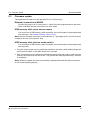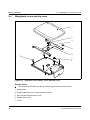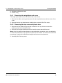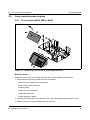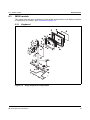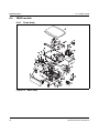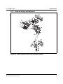
1
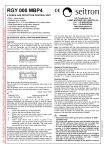
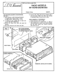
IM Series
Counter Service Scales
Service Instructions
ENGLISH
AWT35-000324-AA
*AWT35-000324*
17-09-2007
©Avery Berkel, 2007. All rights reserved.
The information contained herein is the property of AveryBerkel (a division of ITW Ltd) and is supplied
without liability for errors or omissions. No part may be reproduced or used except as authorized by
contract or other written permission. The copyright and the foregoing restriction on reproduction and
use extend to all media in which the information may be embodied.
Trademarks and acknowledgements
Avery Berkel is a registered trademark in certain jurisdictions. All brands and product names used
within this document are trademarks or registered trademarks of their respective holders.
IMPORTANT
When programming or configuring the equipment you must ensure that you comply with all relevant
standards and legislation. The example settings given in this book may not be legal for trade with the
public.
Contents
page no.
1
Safety and Warnings
5
1.1
Warnings
6
2
Installation
9
2.1
Installation
10
2.2
Cable management
11
2.3
Self service keyboards (IM300)
12
3
Displays and keys
13
3.1
Display
14
3.2
Keyboard overlay
15
4
Service mode
17
4.1
Service mode overview
18
4.2
Enter/Exit service mode
19
4.3
Navigating service mode menus
21
4.4
Diagnostics
22
4.5
Configuration
24
4.6
Calibration
31
4.7
Site gravity
32
4.8
Service PIN
33
4.9
Alternative currency setup
34
4.10
Clone machine
36
4.11 Data clone
37
4.12 Label editor menu
38
4.13 Service setup
43
4.14 Diagnostic logs
49
5
Service procedures
51
5.1
Power up/power down
52
5.2
Calibration
52
5.3
Firmware update
53
5.4
Weighplate, cross and top cover
54
5.5
Customer display assemblies
56
5.6
Front module/vendor displays
59
5.7
Column mounting
63
5.8
Main board
65
5.9
Loadcell
66
IM series Service Instructions
3
4
5.10 Printer
67
6
Exploded views
69
6.1
IM100 models
70
6.2
IM202 models
71
6.3
IM300 models
73
6.4
IM400 models
74
7
Schematics and wiring
77
7.1
External connections
78
7.2
Internal connections
80
8
Module information
85
8.1
Main board
86
8.2
Display PCB
88
9
Networking
91
9.1
Typical networks
92
9.2
Network protocol
94
9.3
Wiring/terminations
94
9.4
Network setup
95
9.5
Network map
99
9.6
Backup server operation
100
9.7
Local mode
101
IM series Service Instructions
Safety and Warnings
1
This chapter contains information about possible hazards and precautions you should
take.
Contents
1.1 - Warnings (page 6)
IM series Service Instructions
5
1.1 Warnings
Safety and Warnings
1.1
Warnings
1.1.1
Installation and service
THE EQUIPMENT CONTAINS NO USER SERVICEABLE COMPONENTS.
Installation and maintenance of the equipment must only be carried out by trained and
authorised personnel.
1.1.2
Electrical installation
The mains lead must be connected to a supply outlet with a protective earth contact. The
electrical supply at the socket outlet must provide over current protection of an
appropriate rating.
Pluggable equipment must be installed near an easily accessible socket outlet.
Permanently connected equipment must have a readily accessible disconnect device
incorporated in the fixed wiring.
USA
If the scale is connected to a 240V supply, the receptacle must be protected by a 15 amp
circuit breaker.
1.1.3
Risk of electric shock
To avoid the possibility of electric shock or damage to the machine, always switch off
the machine and isolate from the power supply before carrying out any routine
maintenance.
Always completely isolate from the power supply before:
O
removing the machine cover(s)
O
performing any routine maintenance
O
cleaning the machine.
1.1.4
Safe handling
To avoid the risk of the machine falling, where applicable, ensure that it is placed securely
on a flat and level surface.
When lifting, moving or supporting the machine, take its weight into consideration.
1.1.5
O
O
O
6
Additional service precautions
When the covers are removed, do not apply power to the unit unless specifically
instructed to do in this handbook.
When working on live equipment, exercise great care, use insulated tools and test
equipment, and do not work alone.
When testing or fault finding, exercise extreme care. Ensure that any test equipment
used is in good condition and capable of withstanding the existing voltages.
IM series Service Instructions
1.1 Warnings
O
Safety and Warnings
All tools used must have insulated handgrips. Test probes and jumper leads must be
in good condition with adequate insulation. Test probes with claw ends and jumper
leads must not have insecure parts that may fail during use.
1.1.6
Replacing batteries
CAUTION: Risk of explosion if battery is replaced by an incorrect type. Dispose of used batteries
according to instructions.
1.1.7
Cleaning the machine
CAUTION: Harsh abrasives, solvents, scouring cleaners and alkaline cleaning solutions,
such as washing soda, should not be used especially on the display windows. Under no
circumstances should you attempt to wipe the inside of the machine.
The outside of standard products may be wiped down with a clean cloth moistened with
water containing a small amount of washing up liquid. The outside of products
waterproofed to IP65, IP66 and IP67 may be washed down with water containing a small
amount of a proprietary detergent.
Cleaning the print head
CAUTION: Do not use metallic objects on the print head. Only use the recommended print
head cleaning kit.
1.1.8
Training
To avoid the risk of RSI (Repetitive Strain Injury) it is important to ensure that the machine
is placed on a surface which is ergonomically satisfactory to the user. It is recommended
that frequent breaks are taken during prolonged usage.
1.1.9
EMC compliance
The following warning may be applicable to your machine.
WARNING:
This is a class A product. In a domestic environment this product may cause radio
interference in which case the user may be required to take adequate measures.
IM series Service Instructions
7
Safety and Warnings
8
1.1 Warnings
IM series Service Instructions
Installation
2
IM300 and IM500 models have additional installation instructions. You should read the
relevant instructions before installing those models.
CAUTION: IM300 and IM500 models should not be installed by one person alone.
Contents
2.1 - Installation (page 10)
2.2 - Cable management (page 11)
2.3 - Self service keyboards (IM300) (page 12)
IM series Service Instructions
9
2.1 Installation
Installation
2.1
Installation
2.1.1
Check list
Kit List
Scale
Power supply
Documentation CD
Quick User Guide
Self service keyboard (IM300 only)
Installation Instructions (IM300 and IM500 only)
2.1.2
Location
Make sure that the work surface or counter is:
O
strong enough to support the weight of the scale
O
stable, steady and free from draughts and vibrations.
2.1.3
Handling
Mis-handling of the scale can affect the scale’s ability to weigh accurately.
2.1.4
10
Levelling
IM series Service Instructions
2.2 Cable management
2.2
Installation
Cable management
Cable clamps
Figure 2.1
External cable routes
IM series Service Instructions
11
Installation
2.3
2.3 Self service keyboards (IM300)
Self service keyboards (IM300)
Single and twin keyboard models
The self service keyboard is supplied as a separate item. It must be connected before the
scale will operate.
Follow the installation instructions (part number AWT35-000308) supplied with the IM300
kit.
CAUTION: Do not attempt to fix the self service keyboards by yourself. Get assistance from
a second person.
Note: After installation you may need to configure the keyboard from within Manager
Mode.
Refer to the User Instructions for further information.
12
IM series Service Instructions
Displays and keys
3
This chapter describes the keyboard and basic key functions.
Contents
3.1 - Display (page 14)
3.2 - Keyboard overlay (page 15)
IM series Service Instructions
13
3.1 Display
Displays and keys
3.1
Display
6
1
2
5
3
4
Figure 3.1
Typical weighing display
1. Metrological information
2. Price per unit
3. Price of goods
4. Product description (PLU text)
5. Weight information (net/tare weight)
6. Model number
14
IM series Service Instructions
3.2 Keyboard overlay
Keyboard overlay
À
A
g
Ä
G
Æ
H
N
M
N
?
S
Ø
Caps
Lock
Ó
*
Ü
:
Ú
Z
Space
(
XXX
£
$
F
/
#
L
K
Ô
!
R
P
U
€
E
°
J
T
Shift ALT
3.2.1
Ö
É
D
Í
O
Z
Y
D
I
N
S
Š
Ç
C
%
G
&
Figure 3.2
C
B
@
Q
+
V
)
R
R
-
=
W
X
.
;
0
7
8
9
4
5
6
1
2
3
0
“
,
=
Á
Å
,
3.2
Displays and keys
Enter
Cntrl
IM202 programming overlay
Keys
Reset the weight display to zero
Subtracts the weight of the container when weighing goods.
In receipt mode, retains the PLU until the transaction is entered.
Retains a tare, if in operation, until it is cancelled.
In label mode, the PLU is retained until it is cancelled.
Sets the scale to pre-pack if the machine configuration allows it.
Cancels a PLU or hand entered price.
Depending on the function in use, clears messages or characters from the display.
Totalises transaction.
In receipt mode, when the subtotal is displayed, prints a receipt.
In label mode, prints a label.
IM series Service Instructions
15
Displays and keys
3.2 Keyboard overlay
Confirms data entry.
Enables you to change the number of items when serving non-weighed items.
Override the programmed price of a PLU.
Cancels an unwanted transaction from an operator subtotal.
In label mode, when set to print totals labels only for ADD key transactions, it
cancels an unwanted transaction from the subtotal.
Depending on machine configuration, allows totals labels or totals and individual
labels to be printed.
Initiates a display test sequence.
Pressed again during the test sequence prints a test report.
Press operator key and type in PIN during test sequence to gain access to Manager
Mode.
Double zero key.
Move to the item above in the displayed list
Move to the item below in the displayed list
16
IM series Service Instructions
Service mode
4
CAUTION: When programming the scale you must ensure that you comply with all relevant
standards. The example settings given in this book may not be legal for trade.
Contents
4.1 - Service mode overview (page 18)
4.2 - Enter/Exit service mode (page 19)
4.3 - Navigating service mode menus (page 21)
4.4 - Diagnostics (page 22)
4.5 - Configuration (page 24)
4.6 - Calibration (page 31)
4.7 - Site gravity (page 32)
4.8 - Service PIN (page 33)
4.9 - Alternative currency setup (page 34)
4.10 - Clone machine (page 36)
4.11 - Data clone (page 37)
4.12 - Label editor menu (page 38)
4.13 - Service setup (page 43)
4.14 - Diagnostic logs (page 49)
IM series Service Instructions
17
4.1 Service mode overview
Service mode
4.1
Service mode overview
Setting the scale into service mode allows you to configure many aspects of the scales
functionality.
Service Mode
Diagnostics
Configuration
Country Config.
Calibration
Site Gravity
Service PIN
Alt. Cncy.
Setup
Diagnostics
Weighing Test
Keyboard Test
Network Test
Calibration
USB Test
Printhead Life
Dynamic RAM
Test
Static RAM
Test
Service PIN
Label Editor
Edit
Format
Label Editor
Restore
Format
Bank 1
Bank 3
Bank 2
Currency
Symbol
Service
Setup
Diagnostic
Logs
Country Config
Alt. Cncy. Setup
Currency
Rate
Copy
Format
Data Clone
Configuration
Site Gravity
Data Clone
Clone
Machine
Bank 4
Clone Machine
Euro
Wizard
Service Setup
List
Format
Printer Setup
Initialise Machine Currency Text
Serial Number
Config Wizard
Model Number
Diagnostic Logs
Print Logs
Figure 4.1
18
Set Log Size
Clear All
Logs
Service mode menu structure
IM series Service Instructions
4.2 Enter/Exit service mode
4.2
Service mode
Enter/Exit service mode
There are two levels of service mode available.
O
Full service access
Full access to all service options including calibration.
O
Restricted service access
Limited access to certain service options. Calibration is not available.
Note: For all service options, you will need the programming overlay on the keyboard.
4.2.1
Full service access
Full service mode allows unrestricted access to the service mode configuration menus.
To enter full service mode:
1. Switch on the scale.
2. On the underside of the scale, locate the access hole for the service switch.
3. Carefully insert a narrow bladed screwdriver until it just touches the service switch
Service switch access
Figure 4.2
Location of service switch access hole.
IM series Service Instructions
19
4.2 Enter/Exit service mode
Service mode
4.2.2
Restricted service access
Restricted access limits the changes you can make to the scale.
Restricted access excludes the following:
1. Changing the capacity
2. Changing the gravity zone compensation
3. Calibrating the scale.
To enter restricted service mode:
1. Switch off the scale and then switch it on again.
2. During the display countdown, enter the service PIN. (Default PIN is 9467.)
Note: To change the service PIN see Service PIN on page 33
4.2.3
Exit service mode
To return to manager or sales mode
20
Press
to return to manager mode.
Press
twice to return to sales mode.
IM series Service Instructions
4.3 Navigating service mode menus
4.3
Service mode
Navigating service mode menus
Use the following keys to navigate the menus:
Enter
Select the item
Enter a value
or
Back
Move up one menu level
Previous
Select previous item
Next
Select next item
Quick save
Save data entered up to this point
Home/Exit
Return to manager mode
Exit service mode
Numeric keypad
Select numbered menu item
IM series Service Instructions
21
4.4 Diagnostics
Service mode
4.4
Diagnostics
Diagnostics
Weighing
Test
Figure 4.3
Keyboard
Test
Network
Test
USB Test
Printhead
Life
Dynamic RAM Static RAM
Test
Test
Flash
Test
Diagnostics menu
The diagnostics menu allows you to perform a number of tests.
4.4.1
Weighing test
Displayed weight
Sub-divisions
Actual weight (number of divisions)
4.4.2
Keyboard test
Select keyboard size
65 - Standard.
84 - Large
TK keyboard 1
TK keyboard 2
O
O
22
Press each key on the keyboard in turn starting from the top left and working towards
the right for each row of keys.
Press the same key three times to exit test.
IM series Service Instructions
4.4 Diagnostics
4.4.3
Service mode
Network test
This tests that the scale’s network is working correctly.
The scale will talk to another device on the network over a number of cycles. A successful
test indicates that the network configuration is working correctly.
4.4.4
USB test
This hardware test checks that the USB port is working correctly.
4.4.5
Printhead life
This is for factory testing purposes only.
4.4.6
Dynamic and static RAM, and Flash test
Checks that the memory is functioning correctly.
IM series Service Instructions
23
4.5 Configuration
Service mode
4.5
Configuration
The configuration tables determine many of the scale’s operating parameters.
Configuration
Bank 1
Figure 4.4
Bank 2
Configuration display
Software version 7.0
Bank 1
Digit
1
Capacity (Not available in restricted access mode)
0
1
2
3
4
5
6
7
Not used
Not used
30lb x 0.01
50lb x 0.01
6kg x 1g
Not used
6kg AVR
Not used
8 15kg x 5g
9 15kg AVR
A Not used
B 30kg x5g
C Not used
D 30lb/15kg
E - T Not used
2
Tare system
0 Free
1 Free, Graduated
2 Free, Cumulative, Graduated
3 Free, Cumulative, Graduated, Proportional
3
Tare display
0 No tare display
1 Negative weight display
4
5
2 10 divisions
3 20 divisions
Bleep behind zero, over range and balance lost
0 Disabled
6
1 Enabled
Numeric entry timeout
0 Disabled
24
2 Separate tare display only
3 Separate tare and negative weight
Minimum weight disturbance
0 1 division
1 4 divisions
7
4 Free, Stored
5 Free, Graduated, Stored
6 Free, Cumulative, Graduated, Stored
7 Free, Cumulative, Graduated, Proportional,
Stored
1 Enabled
PLU auto recall timeout
IM series Service Instructions
4.5 Configuration
Service mode
Bank 1
0
1
2
3
4
None
0.6 seconds
1.0 seconds
0.3 seconds
0.4 seconds
5
6
7
8
9
8
0.5 seconds.
2.0 seconds
3.0 seconds
4.0 seconds
5.0 seconds
Receipt tax printing
0 None
1 Totals tax
2 Itemised tax
9
Weight filter type
0
1
2
3
Settling time 0.2s (71.2Hz)
Settling time 0.5s (71.2Hz)
Settling time 1.0s (71.2Hz)
Settling time 1.9s (71.2Hz)
4
5
6
7
10
Settling time 0.2s (81.2Hz)
Settling time 0.5s (81.2Hz)
Settling time1.0s (81.2Hz)
Settling time1.9s (81.2Hz)
Price base
0 Single price base (lb/kg)
1 Single price base (1/4lb/100g)
11
2 Dual price base (lb/kg)
3 Dual price base (1/4lb/100g)
Printer type
0 None
1 Receipt only
2 Label only
3 Label and Receipt
12
Default sales mode and machine type
0 Hand price mode, weighing
1 PLU price mode, weighing
13
2 Hand price mode, non-weighing
3 PLU price mode, non-weighing
Add function
0 None
1 Transaction + total
2 Total only
14
3 Receipt only
4 Transaction and receipt
Date type
0 Numeric
15
1 Alpha
Date format
0 DD MM YY
1 MM DD YY
2 YY MM DD
16
3 DD MM YYYY
4 MM DD YYYY
5 YYYY MM DD
Maximum transaction sequence number
0 999999
1 99999
2 9999
IM series Service Instructions
3 999
4 99
5 9
25
4.5 Configuration
Service mode
Bank 2
Digit
1
Dummy zero in unit price)
0 6 digit UP, 6 digit TP, no dummy zero
1 6 digit UP, 6 digit TP, dummy zero
2
Transaction rounding
0 Round to nearest 1
1 Round to nearest 5
2 Round to nearest 10
3
3 3 decimal places
4 0 on unit price, 1 on total price
5 Thousands separators
4
Punctuation
0 Decimal point
1 Comma
2 Inverted comma
5&6
Currency symbol
00.
01.
02.
03.
04.
05.
06.
07.
08.
09.
10.
11.
12.
13.
14.
User defined
£
$
R
F (French)
Kr
DM
S
Fr
f
Lit
P
E
K
M
7
15. D
16. RM
17. L
18. N$
19. Esc
20. Pta
21. Rp
22. mk
23. PX
24. SR
25. zt
26. Kc
27. SK
28. kr
29. DHS
30. Won
31. bt
32. Pts
33. EEK
34. Lt
35. €
36. Eur
37. R$
38. B
39. C
40. Q
41. TL
42. F (Belgian)
43. BD
44. LE
45. JD
46. KD
47. LL
48. RO
49. QR
50. SR
51. YR
52. Ft
53. kn
54. Lm
55. Ksh
56. RON
57. ROL
58. LEI
PLU auto recall timeout
0
1
2
3
4
None
0.6 seconds
1.0 seconds
0.3 seconds
0.4 seconds
8
5
6
7
8
9
0.5 seconds.
2.0 seconds
3.0 seconds
4.0 seconds
5.0 seconds
Receipt tax printing
0 None
1 Totals tax
26
3 Round to nearest 25
4 Round to nearest 50
Number of decimal places
0 No decimal places
1 1 decimal place
2 2 decimal places
9
2 5 digit UP, 6 digit TP, no dummy zero
3 7 digit UP, 7 digit TP, no dummy zero
2 Itemised tax
Weight filter type
IM series Service Instructions
4.5 Configuration
Service mode
Bank 2
0
1
2
3
Settling time 0.2s (71.2Hz)
Settling time 0.5s (71.2Hz)
Settling time 1.0s (71.2Hz)
Settling time 1.9s (71.2Hz)
4
5
6
7
10
Settling time 0.2s (81.2Hz)
Settling time 0.5s (81.2Hz)
Settling time1.0s (81.2Hz)
Settling time1.9s (81.2Hz)
Price base
0 Single price base (lb/kg)
1 Single price base (1/4lb/100g)
2 Dual price base (lb/kg)
3 Dual price base (1/4lb/100g)
11
Printer type
0 None
1 Receipt only
2 Label only
3 Label and Receipt
12
Default sales mode and machine type
0 Hand price mode, weighing
1 PLU price mode, weighing
2 Hand price mode, non-weighing
3 PLU price mode, non-weighing
13
Add function
0 None
1 Transaction + total
2 Total only
3 Receipt only
4 Transaction and receipt
14
Date type
0 Numeric
1 Alpha
15
Date format
0 DD MM YY
1 MM DD YY
2 YY MM DD
16
3 DD MM YYYY
4 MM DD YYYY
5 YYYY MM DD
Maximum transaction sequence number
0 999999
1 99999
2 9999
3 999
4 99
5 9
Country configuration
Country config.
Bank 3
Bank 4
Bank 3
Digit
1
Balance key range
0 ± 2%
2
1 ± 5%
+15% -5% Balance at power up
0 Disabled
3
1 Enabled
Large step behind zero
0 Disabled
IM series Service Instructions
1 Enabled
27
4.5 Configuration
Service mode
Bank 3
4
Reduced zero tracking
0 Disabled
5
Retained tare mode
0 Disabled
6
1 Enabled
Manual tare calculation
0 None
1 tare key
7
2 Zero key
3 Tare and zero key
Price interlock/NTEP operation
0 Disabled
1 Price and tare
8
2 NTEP operation.
Fix tare options
0 Fix tare and unit price
9
1 Fix tare only
Open cash drawer with zero total
0 Disabled
10
1 Enabled
Price 1/price 2 swap positions on label
0 Disabled
11
1 Enabled
Receipt total currency symbols
0 Disabled
12
1 Enabled
Minimum prepack weight
0 1 division
13
1 20 divisions
Prepack allows stored/grad tares
0 Disabled
14
1 Enabled
Triple zero key
0 Disabled
15
1 Enabled
Tax system
0 Inclusive
1 Exclusive
16
2 Inclusive, PoS only
3 Exclusive, PoS only
Tax reference in description
0 Disabled
28
1 Enabled
1 Enabled
IM series Service Instructions
4.5 Configuration
Service mode
Bank 4
Digit
1&2
Language
00
01
02
03
04
05
06
07
08
09
10
11
12
13
English (UK)
Spanish
RSA
French
German
Italian
Dutch
Danish
Polish
Czech
Portuguese
Finnish
Norwegian
Turkish
14
15
16
17
18
19
20
21
22
23
24
25
3
Greek
Croatia
Hungary
Sweden
Arabic
English (US)
Romanian
Estonian
Bulgarian
Russian
Ukrainian
English (Arabic)
Sales key layout
0
IM All markets Price Base
4
Manager key layout
0 IM European
1 IM Greek
5
2 IM Arabic
3 IM Cyrillic
Receipt algorithms - transaction count on receipt / display per transaction assigned
0
1
2
3
4
Algorithm
A
B
C
D
E
6
Weighed
1/1 1/1
1/1 1/1
1/1 n/1
1/1 n/1
1/1 n/1
n x (+ve non-weighed)
0/1
1/1
0/1
n/1
0/0
n x (-ve non-weighed)
Receipt formats
0 Receipt format 0 - Italian format which includes tare weight
1 Receipt format 1 - No symbols line, symbols printed with transaction data. First line contains text and
total price. Second line contains weight/multiplier and unit / item price.
2 Receipt format 2 - As receipt format 1 except total price printed on third line for weighed.
3 Receipt format 3 - Symbols line. First line contains text. Second line contains weight/multiplier, unit / item
price and total price.
4 Receipt format 4 - Each transaction contains its own symbols line.
5 Receipt format 5 - USA receipt format. Identical to format 1 except that 'X' and 'Items' is replaced by '@'
6 Receipt format 6 - Australian receipt format. Identical to format 5 except description not allowed to
encroach on the total prices column.
7
Condensed format
0 Disabled
8
1 Enabled
Change calculation
0 Disabled
9
1 Enabled
Direct entry prepack
0 Disabled
IM series Service Instructions
1 Enabled
29
4.5 Configuration
Service mode
Bank 4
10
Net weight
0 Grams
11
1 oz - lb/oz
USA total price legend
0 Disabled
1 Using net weight (per 100g)
2 Using actual weight (Danish)
12
3 Using net weight (per kg)
4 By product type
Back calculation of unit price
0 1 division
1 20 divisions
13 & 14
Country
00
01
02
03
04
05
06
07
08
09
10
11
12
13
14
15
16
17
18
19
20
15
UK
Spain
South Africa
France
Germany
Italy
Netherlands
Denmark
Poland
Czech Republic
Portugal
Finland
Norway
Turkey
Greece
Croatia
Hungary
Sweden
Saudi Arabia
General Export
Indonesia
21
22
23
24
25
26
27
28
29
30
31
32
33
34
35
36
37
38
39
40
41
Frequent shopper algorithm
0 Compute frequent shopper price from printed
weight
1 Compute frequent shopper price from backcalculated weight
16
30
Australia
New Zealand
USA
Ireland
UAE
Canada
Malaysia
Zimbabwe
Lithuania
Estonia
Egypt
Mexico
Panama
Belgium
Switzerland
Austria
Tunisia
Romania
Bulgaria
Russia
Ukraine
2 Compute frequent shopper price from saving and
back-calculated weight
3 Frequent shopper price scheme 3
Not used
IM series Service Instructions
4.6 Calibration
4.6
Service mode
Calibration
1 Ensure you are in full service mode - see page 19.
2 Select Calibration from the available options.
3 If the site and factory gravity factors differ, then you will be prompted to enter the factory
gravity factor. Refer to the local authority for details.
Use the left/right arrows to set the decimal point.
4 Calibrate with zero load.
Ensure there is no weight on the scale, then press ENTER.
5 Calibrate with full load.
Place a full load on the weighplate, then press ENTER.
Note: the last 3 digits will be unstable.
IM series Service Instructions
31
4.7 Site gravity
Service mode
4.7
Site gravity
If the scale has been moved to a different gravity zone, enter the site gravity
compensation factor. Refer to the local authority for details.
Note: This is the gravity factor for the location where the scale is to be used
32
IM series Service Instructions
4.8 Service PIN
4.8
Service mode
Service PIN
You can change the four digit restricted service access PIN from this menu. Only change
the PIN if you think that the user knows the service PIN and is tampering with the
machine's configuration.
IM series Service Instructions
33
4.9 Alternative currency setup
Service mode
4.9
Alternative currency setup
4.9.1
Currency rate and symbol
The currency rate and symbol setup options are used to configure a second currency.
1 Ensure you are in full service mode - see page 19.
2 Select Alt. Cncy Setup from the available options.
3 Press
to select Currency Rate.
4 Enter the required value for the currency.
Note: Use the ‘Previous / Next’ arrows to position the decimal point.
5 Use the ‘Previous / Next’ arrows to select Euro Symbol.
6 Enter the value for the Currency Symbol.
35 = € (See configuration bank 2, digits 5 & 6 for details)
34
IM series Service Instructions
4.9 Alternative currency setup
4.9.2
Service mode
Euro wizard
This converts the PLU file from the local currency to Euro currency. The scale will then
use the Euro as its primary currency.
CAUTION: Only a factory reset can undo this operation.
Euro rate and symbol procedure
1 Ensure you are in full service mode - see page 19.
2 Select Alt. Cncy Setup from the available options.
3 Use the ‘Previous / Next’ arrows to select Euro Wizard.
4 Set how the Euro will appear on the display / labels.
Label
0 = 2nd price field shows alternative currency
1 = 2nd price field shows promotional value
Barcode 0 = Barcode price printed as Euros
1 = Barcode prints alternate currency
Label/ 0 = Euro symbol
Display 1 = Euro text
=
5 Select Yes to complete the process or No to abort.
=Yes
=No
IM series Service Instructions
35
4.10 Clone machine
Service mode
4.10
Clone machine
This function allows you to update another machine on the network so that it is
functionally identical to the one you are using.
The clone function will copy the following information:
O
Executable files (application program)
O
PLU file
O
Label formats
O
Logos
O
Configuration and keyboard layouts
Note: Machine specific information is excluded. (e.g. capacity, calibration data or gravity
compensation factors)
Network ID restrictions
O
O
Application program - can be cloned irrespective of the network IDs of the two
machines.
Data - can be cloned only if both machines are using the same network ID
Clone procedure
1 Ensure you are in full service mode - see page 19.
2 Select Clone Machine from the available options.
3 Enter the IP address of the target machine.
36
IM series Service Instructions
4.11 Data clone
4.11
Service mode
Data clone
Data clone allows you to transfer all the data in one machine to another machine (or
machines) on the network.
The data clone function will copy the following information:
O
PLU file
O
Label formats
O
Logos
O
Configuration and keyboard layouts
Network ID restrictions
O
Data - can be cloned only if both machines are using the same network ID
For more information see Scale groups (Network ID) on page 93.
Clone procedure
1 Ensure you are in full service mode - see page 19.
2 Select Data Clone from the available options.
3 Enter the IP address of the target machine.
IM series Service Instructions
37
4.12 Label editor menu
Service mode
4.12
Label editor menu
Label Editor
Copy
Format
Edit
Format
Restore
Format
List
Format
The scale has 12 (0 - 11) standard label formats and four (12 - 15) nutritional label
formats. This menu allows the label formats to be edited as required. Each label can have
up to 26 fields on it.
Note: The maximum printable area on a label is 160mm x 60mm.
4.12.1 Copy Format
Copy format allows you to create an identical copy of an existing label format. The copy can then
be modified using the Edit Format option (see below).
4.12.2 Edit Format
This allows you to edit the label formats.
At any time you may:
O
Use the ‘List Format’ function to print the current settings.
O
Use the ‘Test’ key to print a sample layout.
Use the `List Format’ function to print the current settings.
1 Ensure you are in full service mode - see page 19.
2 Select Label Editor from the available options.
3 Select Edit Format from the available options.
4 Enter the number of the label format to be edited. (e.g. 5).
5 Use ‘Previous’ or ‘Next’ arrows to select the angle of rotation for the text & graphics on the
label
38
IM series Service Instructions
4.12 Label editor menu
Service mode
6 Enter the number of the field to be edited. (e.g. 8)
7 Use ‘Previous’ or ‘Next’ arrows to select the information that field is to display. (e.g Unit
Price)
8 Use ‘Previous’ or ‘Next’ arrows to select the angle of rotation for the selected field
9 Enter the number (or letter) for the font to be used
10 Enter the X1 and Y1 distances in mm (See field positioning XX)
(Use ‘Previous’ and ‘Next’ arrow keys to select between X1 & Y1)
X1 = distance from left
Y1 = distance from top
IM series Service Instructions
39
4.12 Label editor menu
Service mode
11 Enter the X2 and Y2 distances in mm (See????) (Use ‘Previous’ and ‘Next’ arrow keys to
select between X2 & Y2)
X2 = distance from right
Y2 = distance from bottom
To print a test label
To save and exit
To exit without saving
To move to the next field
Shift
Typical test print
Field area
Field number
Graphic Fld: 13
Ref. = 03
Fld:11
Fld:06
Fld:07
12
Fld:16
Fld:14
d:09
Barcode
Fmt Std: 14 Fld:00
Fld:10
Field reference
Fld:08
Fld:17
Fld:15
Store name
USR - User defined field
STD - Standard default label format
Figure 4.5
40
Note: This field appears in this
position on all labels
Typical label format test print
IM series Service Instructions
4.12 Label editor menu
Service mode
Field position notes
The position of the fields on a label are set by a bounding box. This uses the distances
X1, Y1, X2, Y2; illustrated as follows.
X1 & Y1
View
X2Y2
Label feed direction
X1Y1
Field
or
X1Y1
Field
X2Y2
View
Label feed direction
Field rotation 0°
Field rotation 90°
X2 & Y2
X2Y2
Label feed direction
Field rotation 0°
Field
or
Field
X1Y1
X1Y1
View
X2Y2
View
Label feed direction
Field rotation 90°
Note: The distances are entered for the direction in which the label is being viewed.
IM series Service Instructions
41
4.12 Label editor menu
Service mode
4.12.3 Restore format
This option allows you to restore the specified label format to its factory default.
4.12.4 List format
This option will print out details about all the fields that are used on the specified label
format
*** Label Format List ***
01-11-2000
10.39
Field information
42
Usr Label Format
Label Rotation
3
0B
Field 00 PLU Text
Font D
Co-ords:
0.7.1550.5
0B
Label number
49.3 48.8
IM series Service Instructions
4.13 Service setup
4.13
Service mode
Service setup
Service Setup
Printer Setup
Initialise Machine Currency Text
Serial Number
Config Wizard
Model Number
4.13.1 Printer setup
Do not adjust these settings unless there is a problem with the printer.
Density
This allows you to set the print density on the print out.
1 = light
9 = dark (default = 5).
If the print quality is poor check that the print head is clean. Poor quality printing can be
caused by using inferior quality paper.
Note: For machines with two printers, set the print density for the receipt (second) printer
using the Printer 2 menu option.
Sensor distance
This allows the parking position distance to be adjusted (mm). Default setting is 48.5mm
Note: You will need to reset the opto sensor distancefollowing a Factory Reset or replacing
the main board.
Label threshold (10 - 250)
Set the sensitivity of the label gap sensor.
10 = Very sensitive to gaps between labels.
250 = Not very sensitive to gaps between labels.
Default value = 50
Paper threshold (10 - 250)
Set the sensitivity of the paper sensor.
10 = Very sensitive to presence of paper.
250 = Not very sensitive to presence of paper.
Default value = 100
IM series Service Instructions
43
4.13 Service setup
Service mode
4.13.2 Initialise M/C
This allows you to:
O
Restart the machine
O
Set up the memory allocations.
The options are:
Warm restart
This is the equivalent of switching off the machine and then switching on.
Cold Start
This will restart the machine and clear all the battery-backed RAM. This will delete ALL
records except:
Service PIN
Sub net mask
Label formats and logos
Gateway IP address
Configuration banks
Number of receipts and transactions
Euro rate
Print density
IP address
Distance from sensor
Network ID
Diagnostic log size
Host port number
LCD contrast
Calibration and gravity factors
Factory reset
USE WITH CAUTION!
This will restore the machine to its factory default settings.
Factory reset will delete ALL records except for the MAC (Media Access Control)
address, calibration constants, gravity factors and bank 1, digit 1 of the machine
configuration.
Note: You will need to reset the opto sensor distance after a factory reset.
44
IM series Service Instructions
4.13 Service setup
Service mode
Factory reset values
IP Address
Reset to 88.200.100.5
Network ID
Reset to 0
Host port number
Reset to 3001
Sub net mask
Reset to 255.0.0.0
TCP/IP Gateway Address
Reset to 0.0.0.0 (disabled)
Logos
All (user logos) deleted
Label formats
Reset to default settings
Calibration
Unchanged
Gravity
Unchanged
Configuration banks
Reset to default settings except for digit 1 bank 1
Alt. Cncy. conversion rate
Reset to 1.00
Print density
Reset to 5
Number of receipts and trans.
Reset to 20 receipts and 8 transactions
Distance from sensor to printhead
Reset to 48.5mm
LCD contrast
Reset, but no change until machine is switched off and on.
Service PIN
Reset to 9467
Diagnostic log size
Reset to small
Audit mode
Enabled
Distance printed (mm)
Reset to zero
Delete PLU file
This option deletes all the PLUs stored in the PLU file.
Set Trans Memory
This allows you to set the amount of memory allocated for transactions and receipts.
Memory setting guidelines
Note: Changing memory settings will induce a cold start and should therefore be done
before other (customer) data is set.
Each machine will store transactions according to the ‘Set Trans Memory’ option
(selected from within the ‘Initialise M/C menu).
You can set the following:
O
Num Receipts (Default = 20)
The max number of receipts stored.
O
Num Trans / Recpt (Default = 8, Max = 99)
The max number of individual transactions stored for each receipt.
IM series Service Instructions
45
4.13 Service setup
Service mode
Audit settings
The Trans memory required is closely associated with the Audit settings defined within
manager mode. See the separate user instructions for more information.
Trans memory - Client machines
The memory allocated should reflect the requirements of the installation.
Example:1 - Label
Example scale requirements:
50 labels per hour (1 transaction per label
8 hours trading required in local mode (network fail)
Memory requirements would be
Num Receipts = 400
Num Trans per receipt = 2
Example:2 - Receipt
Example scale requirements:
20 receipts per hour
Average of 4 transactions per receipt
8 hours trading required in local mode (network fail)
Memory requirements would be:
Num Receipts = 160
Num Trans per receipt = 4
Trans memory - Server machines
Settings notes - single servers
For a server, receipts are only stored when live (prior to being totalised). Consequently,
the maximum number of receipts stored will be the same as the number of operators
using the system at any one time.
Example:server requirements:
10 operators on system
Up to 100 live transactions at any one time
(assume equal split between operators)
Memory requirements would be:
Num Receipts = 10
Num Trans per receipt = 10
This would also limit the largest receipt, on the system, to 100 transactions (i.e. 10 x 10).
Note: If an audit trail is required, the number of receipts and transaction stores should be
set according to the length of trail required
46
IM series Service Instructions
4.13 Service setup
Service mode
Settings notes - dual servers
Linear / Circular Buffer
The server buffer can be set to either linear or circular.
Manager Mode
Audit
Server buff mode
Set to linear - If totals and/or audit trail integrity is vital.
The number of receipt stores and transaction stores will determine how long trading
can continue before an audit full condition is reached.
Set to circular - If the ability to continue trading is more important.
The number of receipt & transaction stores will dictate after how long information will
start to be overwritten.
The buffer type is set within manager mode. See the separate user guide for more
information on circular / linear buffers.
Consolidation of dual servers
When communications between dual servers breaks down, both will continue as servers,
potentially with clients. As trading continues on both, totals, receipts and transactions will
be generated. When the servers are reunited, transactions and receipts will be
consolidated, so that both servers will now have a complete set of receipts and
transactions. Totals data will not be collected. It will be regenerated from the receipt and
transaction data.
Note: For server consolidation, audit mode must be enabled.
Delete firmware
USE WITH CAUTION!
This option deletes the .uboot file.
Before selecting this option make sure you have a USB memory stick containing the new
firmware in the root directory connected to the scale. The firmware must have the
filename appimage.uboot.
4.13.3 Currency text
The user defined currency text is 3 digit field that can be used instead of the default
currency text (as set in config bank 2 digits 5 & 6). See Configuration on page 24 for more
information.
Note: To use this user defined currency text, set config bank 2 digits 5 & 6 to 00.
IM series Service Instructions
47
4.13 Service setup
Service mode
4.13.4 Serial Number, Config Wizard, Model Number
Serial number
Factory set scale serial number.
Config wizard.
Enables streamlined Country Configuration on reboot.
Model number
Allows you to enter the three digit model number on the display.
48
IM series Service Instructions
4.14 Diagnostic logs
4.14
Service mode
Diagnostic logs
The scale stores a number of logs to record various events. This option is used to print
and configure the logs.
Print Logs
Select from the following
O
Print system log
O
Print key log
O
Printcomms. log
O
Print all logs
System log: This prints a report showing all the events that have occurred with the
machine, including the number of times that the machine has been switched on and off.
Log number
Events
74 Date: 31:08:99 Time: 09:14:30
Warm boot occurred
Brown outs = 3
Power offs = 3
Reaction time =256μS
Warning time = 115mS
Key log: This prints a report showing which keys have been pressed.
Log number
Key number
74
75
76
77
78
Time:
Time:
Time:
Time:
Time:
09:51:53
09:51:53
09:51:53
09:51:53
09:51:53
Key=63
Key=34
Key=15
Key=27
Key=45
Comms log: This prints a report showing the history of the scale network traffic.
Log number
Key number
74 09:51:53 Sent Packet
36 Bytes in Packet
SCALE INQUIRY Request
00.00.00.24.00.00.00.F1.00.00.
00.00.00.00.00.02.FF.00.00.00.
00.00.00.00.00.00.00.00.00.00.
00.00.00.01.00.
IM series Service Instructions
49
4.14 Diagnostic logs
Service mode
Set log size
This option sets the size of the log. If you select a different log size, then you must cold start the
machine. Log size options are:
O
None - No logs will be stored
O
Small - 100 events. (Uses 30K of the available memory)
O
Medium* - 500 events. (Uses 160K of the available memory)
O
Large* - 1000 events. (Uses 650K of the available memory)
Note: A larger log size will reduce the amount of memory that can be used for PLUs.
* These require a RAM expansion board to be fitted.
Clear All Logs
This clears all the data from the logs.
4.14.1 Printhead life
This is for factory testing purposes only.
50
IM series Service Instructions
Service procedures
5
This chapter describes common service and maintenance procedures.
Contents
5.1 - Power up/power down (page 52)
5.2 - Calibration (page 52)
5.4 - Weighplate, cross and top cover (page 54)
5.3 - Firmware update (page 53)
5.5 - Customer display assemblies (page 56)
5.6 - Front module/vendor displays (page 59)
5.7 - Column mounting (page 63)
5.8 - Main board (page 65)
5.9 - Loadcell (page 66)
5.10 - Printer (page 67)
IM series Service Instructions
51
5.1 Power up/power down
Service procedures
5.1
Power up/power down
On/Off switch
Figure 5.1
Location of On/Off switch
Service notes:
O
Power up / down using the switch shown above.
CAUTION: Even when the unit is switched off, mains voltage is still present inside the unit.
5.2
Calibration
For the calibration procedure see Calibration on page 31
52
IM series Service Instructions
5.3 Firmware update
5.3
Service procedures
Firmware update
The application firmware can be upgraded in one of three ways.
Ethernet connection to MX050
Connect the scale to a PC and select a *.uboot file to be programmed into the scale.
Refer to MX050 Service Instructions for more detail.
USB memory stick (scale service menu)
You must have a USB memory stick containing the new firmware to be programmed
into the scale. See Delete firmware, section 4.13.2.
Note: the new firmware must have a fixed filename of “appimage.uboot”, this file must be
located in the root of the memory stick
USB memory stick (service mode switch)
You must have a USB memory stick containing the new firmware to be programmed
into the scale.
1. Plug the memory stick into the scale then switch on the scale, whilst holding down the
service mode switch on the Main board for 3 seconds.
2. After 3 seconds you can release the switch and the new firmware will be read from the
memory stick and burnt into the scale. (The process will take approximately 2 minutes
to complete)
Note: When the update has been successfully completed the scale will reboot and return
to the normal weighing display.
IM series Service Instructions
53
5.4 Weighplate, cross and top cover
Service procedures
5.4
Weighplate, cross and top cover
1
2
3
4
5
7
6
Figure 5.2
Exploded view of plate, cross and top cover
Service notes:
O
The cross must be fitted with the arrow pointing to the front of the scales.
3. Weigh plate.
4. Rubber seal fitted over cap head screw recess.
5. M6 x 20 cap head screws (2 off).
6. Rubber foot (4 off).
7. Cross.
54
IM series Service Instructions
5.4 Weighplate, cross and top cover
Service procedures
8. Weights and Measures seal
9. Rubber bung
5.4.1
Removing the weighplate and cross
The weigh plate rests on the four rubber feet on the cross.
1. Remove the rubber seal to gain access to the two cap head screws in the centre of the
cross.
2. Remove the two cap head screws retaining the cross and lift off the cross.
5.4.2
Removing the top cover and printer door
1. Remove the five rubber bungs and the screws from the top of the cover and the
retaining screw in the printer housing.
2. Remove the Weights and Measures seal and the screw beneath the seal.
Note: Once this seal has been broken or removed certain procedures, such as calibration
or load cell replacement, may require the scale to be re-verified. You should ensure that all
procedures comply with local/national weights and measures requirements.
3. Carefully lift off the top cover.
IM series Service Instructions
55
5.5 Customer display assemblies
Service procedures
5.5
Customer display assemblies
5.5.1
IM100
Figure 5.3
Removing the customer display
Service notes:
1. Remove weigh plate, cross and top cover (see Weighplate, cross and top cover on
pages 54 and 55).
2. Disconnect the rear display cable assembly.
3. Lift the customer display assembly clear of the base cover.
56
IM series Service Instructions
5.5 Customer display assemblies
5.5.2
Service procedures
IM300 keyboard assembly
1
Figure 5.4
Disassembling the self service keyboard
Service notes:
The spacers (1) are an essential part of the assembly and must be replaced when reassembling the unit.
The connection between the keyboard loom and keyboard tail must be sealed with
adhesive tape.
1. Remove the four screws retaining the rear cover support plate.
2. Disconnect the keyboard cable assembly from the rear cover support plate.
3. Remove the six screws securing the keyboard assembly and keyboard mat to the front
cover assembly.
Note: Reverse the procedure to assemble the self service keyboard.
IM series Service Instructions
57
5.5 Customer display assemblies
Service procedures
5.5.3
IM400 customer display
Figure 5.5
Disassembling the customer display
Service notes:
It is not necessary to remove the complete head assembly.
For easier access you can place the scale upside down on a suitable surface with the
column and head assembly hanging down over the edge.
1. Remove the two screws securing the lower cover and remove the cover.
2. Disconnect the two display cable assemblies for the display interface.
3. Remove the two screws securing the upper cover and bezel assemblyand remove them
from the head.
4. Remove the star washer and unclip the display assembly and bezel from the upper
cover.
5. Remove the two screws securing the display interface assembly to the bezel.
Note: Reverse the procedure to assemble the customer display assembly.
58
IM series Service Instructions
5.6 Front module/vendor displays
5.6
Service procedures
Front module/vendor displays
5.6.1
Front module IM100, IM202, IM300
Figure 5.6
Removing the front cover and display interface
Service notes:
Removal of the front cover allows access to the vendor display and keyboard.
1. Disconnect the following cables from the main board:
Front and rear display cable assemblies
Power input power assembly
Earthing strap
Load cell cable assembly
USB cable assembly
Printer assembly cables
2. Carefully free the main board assembly from the two retaining clips and lift it clear.
3. Remove the two screws retaining the front module.
IM series Service Instructions
59
5.6 Front module/vendor displays
Service procedures
4. Unclip the front module and slide it forward until it is clear of the base moulding.
Note: It may not be necessary to completely remove the main board before removing the
front module. Disconnect the earth strap and the USB cable assembly from the main board
then stand the main board up to access the two screws.
5.6.2
Vendor display and keyboards
Figure 5.7
Removing/replacing the display interface assembly
Service notes:
Monobloc and tower models
1. Remove weigh plate, cross and top cover (see Weighplate, cross and top cover on
pages 54 and 55).
2. Follow steps 1 to 4 of Front module IM100, IM202, IM300 on page 59
3. Disconnect the front display cable assembly and the keyboard screen cable
assemblies.
4. Remove the two retaining screws and lift the display assembly clear of the front cover.
Two piece models (IM400)
1. Follow steps 1 to 3 on page 58 to remove the lower cover and the customer display and
bezel assembly.
2. Disconnect the display cable assembly, the keyboard and screen cableassemblies.
3. Remove the two retaining screws and lift the display assembly clear of the front cover.
Note: For better access you can remove the keyboard/display module from the mounting
plate.
1. Remove the two screws and washers securing the module to the mounting plate
60
IM series Service Instructions
5.6 Front module/vendor displays
Service procedures
2. slide the module off the mounting plate.
5.6.3
Vendor display (IM202)
Insert screwdriver
Insert screwdriver
Figure 5.8
Tower display
Service notes:
1. Gently insert a 7mm flat bladed screwdriver into one of the access holes in the lower
cover until it locates in the slot in the clip. Turn it hrough 90 degrees and push upwards.
Repeat with the other access hole.
2. Lift the upper cover to remove it.
3. Lift out the display interface assembly and disconnect the display cable assembly.
4. To remove the lower cover undo the four socket head cap screws securing it to the
column.
IM series Service Instructions
61
Service procedures
5.6 Front module/vendor displays
Replacing a display interface
Take care to replace the display interface in the correct position.The customer and
vendor displays are not interchangeable as they have different jumper settings.
62
IM series Service Instructions
5.7 Column mounting
5.7
Service procedures
Column mounting
5.7.1
IM202, 400
Figure 5.9
Attaching the column mounted display
Service notes:
It is advisable to remove the display pod from the column before attempting to attach or
remove the column from the scale body. The display and column assembly is top heavy
when separated from the scale body.
1. Remove weigh plate, cross and top cover (see Weighplate, cross and top cover on
pages 54 and 55)).
2. Push up the column bracket cowl to unclip it from the base cover.
3. Remove the socket head cap screw and the earth strap.
4. Slide the column support bracket backwards away from the base cover to release it.
1. Remove the four socket screws attaching the column support bracket to the column.
2. Slide the column bracket cowl off the column.
When replacing looms, thread them through from the top of the column and through the
holes provided in the column support bracket.
IM series Service Instructions
63
5.7 Column mounting
Service procedures
5.7.2
IM300
Figure 5.10 Attaching the IM300 column and display (single keyboard
configuration)
Service notes:
For details of IM300 twin keyboard configuration and assembly see the IM300 installation
kit instructions AWT35-000308
64
IM series Service Instructions
5.8 Main board
5.8
Service procedures
Main board
Figure 5.11 Removing the main board.
Service notes:
1. Remove weigh plate, cross and top cover (see Weighplate, cross and top cover on
pages 54 and 55)).
2. Disconnect the following cables from the main board:
Front and rear display cable assemblies
Power input power assembly
Earthing strap
Load cell cable assembly
USB cable assembly
Printer assembly cables
3. Carefully free the main board assembly from the two retaining clips and lift it clear.
Note: The two screws shown are not fitted. Should the retaining clips break, then use two
self tapping screws of an appropriate size (M3 or smaller, less than 8mm length) to secure
the main board.
IM series Service Instructions
65
5.9 Loadcell
Service procedures
5.9
Loadcell
Figure 5.12 Removing the loadcell
Service notes:
1. Remove weigh plate, cross and top cover (see Weighplate, cross and top cover on
pages 54 and 55)).
2. Remove the pan head retaining screw and the earth straps.
3. Disconnect the load cell cable assembly from the main board.
4. Remove the four cap head screws retaining the load cell assembly and remove the
load cell.
66
IM series Service Instructions
5.10 Printer
5.10
Service procedures
Printer
5.10.1 Printer assembly
Figure 5.13 Removing the printer
Service notes:
1. Remove the USB support bracket.
2. Disconnect the earth strap from the printer.
3. Disconnect from the main board:
the printer optical sensor cable assembly
the printer stepper motor cable assembly
the printhead interface cable assembly.
4. Remove the three screws securing the printer assembly to the base cover.
IM series Service Instructions
67
Service procedures
68
5.10 Printer
IM series Service Instructions
Exploded views
6
This chapter contains exploded views of the main assemblies. Full explodes views and
part numbers can be found in the IM series Parts List
Contents
6.1 - IM100 models (page 70)
6.2 - IM202 models (page 71)
6.3 - IM300 models (page 73)
6.4 - IM400 models (page 74)
IM series Service Instructions
69
6.1 IM100 models
Exploded views
6.1
IM100 models
6.1.1
Scale body
Figure 6.1
70
Monobloc model scale body
IM series Service Instructions
6.2 IM202 models
6.2
Exploded views
IM202 models
6.2.1
Scale body
Figure 6.2
Scale body for head up/tower display models
IM series Service Instructions
71
6.2 IM202 models
Exploded views
6.2.2
Head up display
Figure 6.3
72
Head up/tower customer and vendor display
IM series Service Instructions
6.3 IM300 models
6.3
Exploded views
IM300 models
This model uses the same scale body as the IM100 except that the rear display interface
is replaced by an overlay. (see Scale body on page 70)
6.3.1
Keyboard
Figure 6.4
Single keyboard configuration
IM series Service Instructions
73
6.4 IM400 models
Exploded views
6.4
IM400 models
6.4.1
Scale body
Figure 6.5
74
IM400 body
IM series Service Instructions
6.4 IM400 models
6.4.2
Exploded views
Head up display and keyboard
Figure 6.6
IM400 keyboard and vendor/customer display.
IM series Service Instructions
75
Exploded views
76
6.4 IM400 models
IM series Service Instructions
Schematics and wiring
7
CAUTION: When programming the scale you must ensure that you comply with all relevant
standards. The example settings given in this book may not be legal for trade.
Contents
7.1 - External connections (page 78)
7.2 - Internal connections (page 80)
IM series Service Instructions
77
7.1 External connections
Schematics and wiring
7.1
External connections
7.1.1
Overview
4
5
6
3
2
1
Figure 7.1
Overview of external connections
1. On/Off switch
2. Cash drawer
3. Power supply
4. Expansion interface (Wifi)
5. USB (scanner)
6. Ethernet network connector
7.1.2
Scanner connection
The scanner should be connected to the USB port or the extended USB connector
underneath the scale.
Serial setting
78
O
9600 Baud
O
No parity
O
1 stop bit
IM series Service Instructions
7.1 External connections
Schematics and wiring
The scanner must be configured to interpret EAN/UPC family barcodes or Code 39
barcodes. The type of barcode will depend on the application to be used.
Refer to the instructions supplied by the scanner manufacturer for details of how to do
this.
7.1.3
Expansion Interface (P11)
Pin
1
Function
+VS
2
3
+3V3
4
0V.
5
EXP I/O pin 1 (SCLK)
6
EXP I/O pin 2 (SDI)
7
EXP I/O pin 3 (SDO)
8
EXP I/O pin 4 (CS_bar)
9
USB serial data+
10
USB serial data-
11
RESET_bar
12
13
RS232-RXD
14
RS232-TXD
15
RS232-RTS
16
RS232-CTS
IM series Service Instructions
79
7.2 Internal connections
Schematics and wiring
7.2
Internal connections
7.2.1
IM100
Figure 7.2
80
Main board, displays, keyboard, transducer and printer
IM series Service Instructions
7.2 Internal connections
7.2.2
Schematics and wiring
IM202
Figure 7.3
Main board, displays, keyboard, transducer and printer
IM series Service Instructions
81
7.2 Internal connections
Schematics and wiring
7.2.3
IM300 body
Figure 7.4
82
Main board, loadcell, front display/keyboard, printer.
IM series Service Instructions
7.2 Internal connections
7.2.4
Schematics and wiring
IM300 keyboards
Figure 7.5
IM300keyboards
IM series Service Instructions
83
7.2 Internal connections
Schematics and wiring
7.2.5
IM400 loadcell, displays and keyboard
Figure 7.6
84
Main board, loadcell, displays and keyboard
IM series Service Instructions
Module information
8
This chapter contains layout and electrical information for PCBs and hardware within the
scale.
Contents
8.1 - Main board (page 86)
8.2 - Display PCB (page 88)
IM series Service Instructions
85
8.1 Main board
Module information
8.1
Main board
8
9
7
6
10
5
11
4
3
Figure 8.1
86
2
1
16
15
14
13
5
12
AWT25-000094
1.
J7
Cash drawer
2.
J1
Power supply
3.
P15
On/Off switch
4.
P8
Printer opto sensor
5.
J6, J4 Front and rear displays (interchangeable)
6.
P7
Printer stepper motor
7.
P6
Print head interface
8.
P10
Load cell
9.
P9
USB
10. P5
Multi-ICE (not fitted)
11. P3
Battery back-up (normally on)
P2
Reset (normally off)
P12
Debug (normally off)
IM series Service Instructions
8.1 Main board
Module information
P4
Debug (normally off)
12. BT1
Battery
13. J5
Ethernet
14. J3
USB (usually scanner)
15. P11
Expansion interface (Wifi)
16. P13
Wlan (not used)
8.1.1
Pin outs
Loadcell connector
Pin
Function
1
Load cell power
2
0V
3
Serial data from load cell
4
Serial data to load cell
5
Serial clock to load cell
6
Load cell select
IM series Service Instructions
87
8.2 Display PCB
Module information
8.2
Display PCB
There are two variants of the display interface depending on whether the interface board
is driving screens/screens and keyboard or keyboard only.
Model
Description
Module 1
Module 2
IM100
Mono scale
Display and keyboard
Display
IM202
Tower scale
Keyboard
Display
IM300 (1)
Self service scale
Display and keyboard
Keyboard
IM300 (2)
Self service twin head
scale
Display and keyboard
Keyboard
IM400
Two piece scale
Display and keyboard
Display
IM500
Hanging scale
Display and keyboard
Display
8.2.1
Module 3
Display
Display
Display/keyboard variant
This PCB is used for both customer and vendor displays.
It drives the graphics panel and can be connected to a membrane keyboard.
1
2
LK1
3
4
LK2
7
5
6
Figure 8.2
AWT25-000092
1. To main board or another display board
These connectors are interchangeable.
88
IM series Service Instructions
8.2 Display PCB
Module information
2.
Keyboard screen tail
3.
Keyboard earth
4.
Bleeper
5.
Address configuration links (see table)
6.
Not fitted (programming - factory use only).
7.
Not fitted on display variant.
8.2.2
Keyboard only variant
This PCB can be connected to a membrane keyboard and a self service keyboard. It
does not support a graphics panel.
1
2
LK1
3
4
LK2
7
5
6
Figure 8.3
AWT25-000235
1. To main board or another display board
These connectors are interchangeable.
2.
Keyboard screen tail
3.
Keyboard earth
IM series Service Instructions
89
8.2 Display PCB
Module information
4.
Bleeper
5.
Address configuration links (see table)
6.
Not fitted (programming - factory use only).
7.
Self service keyboard connector (P3).
8.2.3
Link settings for display interface
AWT25-000092
Module 1
LK1
LK2
Resistor link
Front display and keyboard
IM100, IM300, IM400
Keyboard on
ON
Front
ON
Not fitted
Front display only
IM202
Keyboard off
OFF
Front
ON
Not fitted
OFF
Not fitted
OFF
Not fitted
Test mode
ON
Rear display only
IM100, IM202, IM400
Keyboard off
OFF
Rear
AWT25-000235
Module 1
Iinternal keyboard
IM202
LK1
Keyboard 1
Test mode
90
ON
LK2
Internal
OFF
Resistor link
ON
Fitted
ON
Fitted
Self service 1
IM300
Keyboard 1
ON
Self service
OFF
Fitted
Self service 2
IM300
Keyboard2
OFF
Self service
OFF
Fitted
IM series Service Instructions
Networking
9
A network allows a number of scales to be connected together. Scales on a network can
share resources and information
Contents
9.1 - Typical networks (page 92)
9.2 - Network protocol (page 94)
9.3 - Wiring/terminations (page 94)
9.4 - Network setup (page 95)
9.5 - Network map (page 99)
9.6 - Backup server operation (page 100)
9.7 - Local mode (page 101)
IM series Service Instructions
91
9.1 Typical networks
Networking
9.1
Typical networks
9.1.1
Introduction
A network allows a number of scales to be connected together. Scales on a network can
share resources and information (operators, PLUs etc.).
Networked scales are assigned to groups. The network can contain up to 99 groups,
each having up to 10 scales. See
The machines can be connected to either one physical network hub or to several hubs.
Two scales can be connected together without the use of a hub. A simple cross cable is
used to connect the two machines together.
9.1.2
Multi scale network
Scales are connected together using one or several hubs as required. The number and
position of the hubs required is determined by the store layout and the type of hub used.
For example, hub arrangement could be affected by:
O
Proximity of machines to each other.
O
Number of network inputs available at each hub.
Figure 9.1
92
Typical multi-scale network
IM series Service Instructions
9.1 Typical networks
9.1.3
Networking
Scale groups (Network ID)
Network ID = 1
(Grpoup 2)
Network ID = 0
(Grpoup 1)
Network ID = 2
(Grpoup 3)
Figure 9.2
Network with scale groups
O
Machines can be put into groups of up to ten scales.
O
The scale group is assigned by the network ID number.
O
Up to 99 groups of scales can be connected to a network, giving a total of 990 scales.
O
Each group of scales will have a server and a number of client scales.
Note: For scales to share PLU information etc. with each other, they must be within the
same group. (I.E. have the same network ID number
See Manual network configuration on page 96 for details of network ID and other settings.
IM series Service Instructions
93
9.2 Network protocol
Networking
9.2
Network protocol
IM series scales’ network protocol and speed are as follows:
9.3
O
TCP ICP protocol.
O
10Mbs or 100 Mbs, 10 base T ethernet connection.
Wiring/terminations
Note: Before setting up an in-store network, obtain the appropriate IP addresses from the
store IT administrator.
Enter the addresses at the machines before connecting the network. See 9.4, Network
setup for more information.
For wiring and termination details refer to the ‘Connecting PC networks’ book, part
number 76102-559.
9.3.1
Cable lengths
The maximum cable length between each machine and the hub is one hundred metres.
Note: It is usual to allow 5m at either end for the patch cable from the scale to the wall
socket. This allows 90m for the cable run between network wall socket and patch panel.
If the connections between hubs use 10 base T connections, then there should be no
more than four hubs in series.
94
IM series Service Instructions
9.4 Network setup
9.4
Networking
Network setup
The network settings are configured from within manager mode.
To enter manager mode you can:
1. Enter service mode (see page 19).
2. Press the
key on the programming overlay.
or
1. From sales mode, press
and enter the manager PIn.
2. Follow the steps on screen.
For more detailed information on the manager menu operation see the separate user
instructions.
Set up notes:
O
For DHCP networks, set the IP address at each scale to 0.0.0.0.
IP addresses will then be allocated by the DHCP server for the network.
O
O
For new installations, using Auto Configure to install machines to a network is a very
quick way of getting all the machines working.
Where Auto Configure is not suitable you can manually alter each machine’s network
settings.
9.4.1
Auto Configure
You can use this function to set up a stand-alone network of scales ‘out of the box’.
Auto configure will:
O
O
O
Detect all the machines that are connected to the network and have the same network
ID.
If there are no servers, it will make the machine that you are using into the server. The
machine ID will be made into ID1 or the next available ID number. The server will then
find each client machine in turn and give it a machine ID.
If a server already exists, then the machine you are using will become a client machine
and be given the next available machine ID.
Note: This option will only assign scales within a single group. (i.e up to 10 scales, having
the same network ID.
For greater than 10 scales, only 10 will be auto-configured. The remainder must be
manually configured to be in a different group (with a different network ID).
O
Machine IDs will be allocated in no particular order, so may not follow any logical
pattern.
IM series Service Instructions
95
9.4 Network setup
Networking
Auto configuration procedure:
1. Connect all the scales to the network hub and switch on.
2. Ensure that the network ID at each scale is set.
3. At the server scale, go to ‘Auto configure’ and press
.
The scale that you are using will automatically detect the other scales within the group.
This machine will become the server and the rest of the machines will be client
machines.
Auto configure can also be used to add a new scale into an existing group. When doing
this you may need to update the scale's PLU file by performing a network dump.
1. Connect all the scales to the network hub and switch on.
2. Ensure that the network ID at each scale is set.
3. At the server scale, go to ‘Auto configure’ and press
.
The scale that you are using will automatically detect the other scales within the group.
This machine will become the server and the rest of the machines will be client
machines.
Auto configure can also be used to add a new scale into an existing group. When doing
this you may need to update thescale's PLU file by performing a network dump.
9.4.2
Manual network configuration
For each scale,you may manually configure the settings described in this section.
Machine ID
Used to set the scale’s ID within its group.
Setting
Description
Machine ID
0 = stand alone scale (not networked).
1 - 10 = The machine ID within its group of
scales.
Server / Client
Set the scale to be either a server or a client
scale.
Before setting a client machine to be a server you should:
O
clear all transactions.
O
clear all totals.
If a server already exists on the network then:
96
O
the new server becomes the back up server.
O
an existing back up server will revert to client status.
IM series Service Instructions
9.4 Network setup
O
Networking
If you change a back up server to be a server, the old server becomes the back up.
Note: See Backup server operation on page 100, for more information.
Network dump
For a group of scales (all sharing the same network ID); this option synchronises all data held at
the client machines with that of the server.
M/c Setup dump
This option transfers all machine information (not system data) to the specified scale.
9.4.3
Advance settings
If you are installing a scale to an established network, then you must gather information
about the network. The easiest way to do this is to use an existing scale to print a test
report (press the test key twice). The settings of the new scale must be set so it will
communicate with the existing scales on the network.
IP Address / Sub net mask
The IP address of the scale consists of two parts, the network address and the machine
address. The network address must be the same as all the other scales on the same
network, and the machine address must be different from the other scales on the same
network.
The network address depends on which sub-net mask is used, for example for an IP
address of 88.1.1.7:
Sub-net mask
255.0.0.0
255.255.0.0
255.255.255.0
Network address
88.1.1.7
88.1.1.7
88.1.1.7
Machine address
88.1.1.7
88.1.1.7
88.1.1.7
For DHCP networks, set the IP address at each scale to 0.0.0.0. IP addresses will then
be allocated by the DHCP server for the network.
Note: When manually setting up a network (i.e. DHCP is not applicable), obtain the IP
addresses from the store IT administrator. Enter the addresses at the machines before
connecting the network.
Host name
For networks using DHCP, a unique text identifier may be programmed for each scale on
the network.
Gateway IP address
A gateway can be used to bridge between 2 devices with different network addresses.
The gateway will have a network address the same as the scale’s and will re-route
communications as required.
IM series Service Instructions
97
9.4 Network setup
Networking
Network ID
A number 0-99 which is used to assign a scale to a particular group. See Scale groups
(Network ID) on page 93.
Host port number
The host port number should only be changed if there is a conflict between the scale and
some other piece of equipment. All machines in the same network must have the same
base port number.
Ping IP Address
Used to test communications between the scale and another known IP address.
Data clone
Clones data from this scale to another within the same group. See Data clone on page 37.
9.4.4
Removing a scale
A scale can be removed from the network using the following option:
Manager mode >> Communication >> Machine ID
In brief
To remove a client scale from the network:
O
Go to the client to be removed and set the machine ID to 0.
This will remove the client from the network and also inform the server of the change.
To remove a scale that is already off-line (fault reported at the server):
1. Go to the server and view the network map.
2. Press
to accept the map.
3. Press Yes to save the change (and clear the fault)
98
IM series Service Instructions
9.5 Network map
9.5
Networking
Network map
The network map shows the status of all the machines in the network group.
Max 15kg Min 100g e=5g
IM 100
1 - 10
SCCOXXCCCX
O
Press
S = Server
B = Back up server
C = Client
O = Off-line
E = PLU file error
X = No machine present
L = Local mode
to accept the map
Note: If a machine has been removed from the network, pressing ‘Yes’ to save will remove
it from the network map.
IM series Service Instructions
99
9.6 Backup server operation
Networking
9.6
Backup server operation
The backup server is a backup of the primary server. It is synchronised with the primary
and hence contains identical information. It is used as a fail-safe for when the primary
server is off line.
O
O
O
O
O
O
O
O
O
100
If the primary server goes down, the backup server will become the primary server.
When restored, the previous primary server will become the backup server.
The receipt and transaction memory settings on the backup server must be identical to
the main server.
Although the backup and server continuously synchronise, the system should not be
operated for extended periods with one server switched off. If this is the case (e.g.
repair) the totals, transactions and the audit list should be cleared before reinstating a
second server to ensure that they are synchronised.
The date and time of synchronisation start and finish is stored in the system log.
If you attempt to clear totals or transactions with backup off-line, a warning message is
given.
If more than one server is set the server that powers up first will be the primary server
with the second set to the backup server.
In the instance of a communications failure between backup and primary servers, the
backup server will become primary, when the cable is reconnected there will be two
servers. In this instance the first server to detect this will demote the other to backup
server.
The backup server acts as client in terms of clearing totals etc. i.e. the request is sent
to the primary server, the backup server will also perform the request locally.
If both servers have failed the client will ask if the user wishes to enter local mode. on
confirmation all totals and transactions will be cleared from the client local memory.
The first transaction or total request, for each operator on the local machine will
display a warning to re-enter transactions.
IM series Service Instructions
9.7 Local mode
9.7
Networking
Local mode
If a client scale becomes disconnected from the server (e.g. because of a network fault).
It will operate in local mode.
A machine operating in local mode will generate and store, totals, receipts and
transactions locally.
9.7.1
Local mode recovery
When the network is restored, the server will recover transaction data from all machines
in local mode, and restore all local machines as clients.
The server will then re-generate the local machine totals using the transaction data
collected.
Note: If the local mode machine fails to store all transactions (e.g. because of insufficient
memory) then the totals generated by the server will be incorrect.
9.7.2
Transaction memory in local mode
For a scale operating in local mode, the transaction memory stores both live and cleared
transactions until the server is back on line and able to synchronise the data. It is
therefore important that sufficient transaction memory is allocated. See Memory setting
guidelines on page 45.
IM series Service Instructions
101
Networking
102
9.7 Local mode
IM series Service Instructions
Index
A
F
ADD key 16
Alternative currency 34
currency rate and symbol 34
Auto Configure 96
Factory reset 44
Factory reset values 45
Field position 41
Fix key 15
B
G
Backup server 100
Gravity 32
C
I
Calibration 31
Clear key 15
Client 93
Clone
data 37
machine 36
Cold Start 44
Comms log 49
Configuration tables 24
country configuration 27
Currency text 47
Initialise 44
Initialise machine 44
IP Address 97
IP addresses 95
D
Data clone 98
DHCP 95, 97
Diagnostics 22, 23
dynamic RAM test 23
keyboard test 22
network test 23
printhead life 23
weighing test 22
Dual server 47
E
Edit Format 38
Enter key 16
Euro wizard 35
setup 35
Explode views
IM100 body 70
IM202 head up display 72
IM202 scale body 71
IM300 self service keyboard 73
IM400 display and keyboard 75
IM400 scale body 74
IM series Service Instructions
K
Key log 49
L
Label editor 38
Log size 50
M
M/c Setup dump 97
Machine address 97
Machine ID 96
Memory settings 45
guidelines 45
N
Network 92
Advance settings 97
auto configure 95
backup server 100
cable lengths 94
data clone 98
gateway 97
host name 97
host port number 98
local mode 101
local mode recovery 101
local mode transaction memory 101
map 99
primary server 100
setup 95
sub net mask 97
103
wiring 94
Network address 97
Network dump 97
Network ID 93, 98
O
Override key 16
P
Price base key 16
Primary currency 35
Print Logs 49
Printer setup 43
density 43
sensor 43
Printhead life 50
server 46
V
Void key 16
W
Warm restart 44
Wiring
networks 94
Z
Zero key 15
R
Restart 44
S
Secondary currency 34
Server 93
Service mode 17, 51, 77, 91
enter/exit 19
full service access 19
navigating menus 21
overview 18
restricted service access 20
Service PIN 33
Service procedures
column mounting 63
customer display 56
firmware update 53
front module/vendor displays 59
loadcell 66
main board 65
replacing a display 62
tower display 61
vendor display and keyboards 60
Service setup 43
Single server 46
System log 49
T
Total/print key 15
Trans memory
client 46
104
IM series Service Instructions
IM series Service Instructions
105
Avery Berkel
Foundry Lane,
Smethwick, West Midlands,
England B67 9DF
Tel: +44 (0)870 903 2000
Email: [email protected]
www.averyberkel.com