1
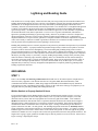
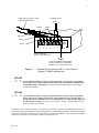
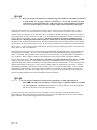
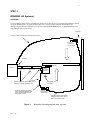
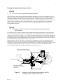
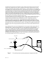
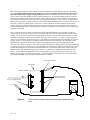
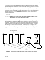
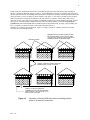
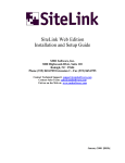
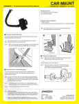
PROPERTY SENTINEL™ LIGHTNING AND BONDING GUIDE Sentinel Systems Corporation 1620 Kipling Street Lakewood, CO 80215 Phone: 800-456-9955 Rev. 1.22 6/30/98 1 Lightning and Bonding Guide This checklist serves to help simplify, inform and ensure that your storage facility has been installed with the basic bonding and grounding features necessary to protect it from lightning, electrical noise and other possible electrical phenomenon. It was designed and written to be easily understood by eliminating highly technical discussion, vocabulary, and terms associated normally with this subject matter. The checklist acts as a straightforward approach to educate, assist and aid in the most general sense, the fundamentals associated with grounding and bonding a typical storage facility. In addition, this checklist is not intended or approved to act as a substitute or replacement for National Electrical Code (NEC) requirements. It serves to act as a general, informational, and instructive approach to grounding and bonding a typical storage facility, and in no way should be viewed as a complete and detailed description of all topics or subject matter related to bonding and grounding issues. It should also be emphasized that there are no provisions or guarantees of complete avoidance of electrical complications. Regardless of how well a facility or structure is bonded or grounded, it should never be considered exempt or immune to or from any and all electrical phenomenon such as lightning or electrical noise. Bonding and grounding issues are extremely important to the protection, performance and operation of your Sentinel Systems security products. A properly bonded and grounded storage facility is much less susceptible to electrical occurrences such as electrical noise and lightning. The terms bonding and grounding simply mean to connect various equipment together to an earth ground potential. This is done to eliminate the possibility for a difference in potential to develop between two or more important electrical and/or mechanical devices, equipment or components that may be providing security to your facility. Properly bonding and grounding a storage facility will also greatly reduce the chance of attracting surges caused by lighting. Below is a checklist that will aid, instruct and help to ensure that your storage facility is properly grounded and bonded. Please read each question and check “YES” or “NO” for each of the topics presented below. If you have checked “NO” to any of these topics, it is extremely important that you make any necessary arrangements and adjustments to completely fulfill any grounding and/or bonding requirements described. GROUNDING: STEP 1 There is one and only one electrical ground location that should exist for all Sentinel Systems computer-based electrical security equipment. This includes such devices as keypads, DSBs (Door Status Boards), CIMs (Communication Interface Modules), SSMs (Surge Suppression Modules) and standalone Property Sentinel II Central Processor Units. Depending on the model or system you have will dictate what type of equipment you are using and where the particular grounding and bonding should occur. WinSen Sentinel or Property Sentinel III Users If you own the Sentinel Systems WinSen Sentinel or Property Sentinel III gate interface software, your site is equipped with a CIM that is located within approximately 6 feet of your PC (Personal Computer). The CIM interfaces between your PC and various peripheral devices such as keypads and/or DSBs. A four conductor shielded communication cable (Belden 9418 or equivalent) should be attached to the CIM as shown in Figure 1 illustrated on Page 2 and in Drawing 28 of your Property Sentinel User's Manual. Notice that the shield of this communication cable is terminated at TB1-7 of the CIM. Figure 1 on Page 2 and Drawing 28 also illustrate a separate connection from TB1-7 to earth ground. The shielding and ground connections are absolutely vital for proper performance, protection and operation of your Sentinel Systems security products. A 12 gauge (12 AWG) stranded copper wire can be used to connect TB1-7 of the CIM to earth ground. A cold-water-pipe or the ground terminal of a standard 115 VAC receptacle can be used as the ground electrode for the earth ground connection. The length of the 12 gauge, copper ground wire should be kept as short as possible not to exceed 20 feet. Please refer to Figure 2 on Page 3 depicting this concept. Rev. 1.22 2 TO POWER SUPPLY COMM. CABLE, 18 AWG, 4 COND., SHIELDED, BELDEN 9418 GREEN SHIELD RED BLACK WHITE 1 2 3 4 5 6 7 8 COMM. INTERFACE MODULE (CIM), MODEL 430 12 AWG, STRANDED, COPPER WIRE TO COLD WATER PIPE, OR GROUND TERMINAL OF 115 VAC RECEPTACLE Figure 1: Electrical ground location at TB1-7 of the CIM via a 12 gauge (12 AWG) stranded wire. YES NO 1) Is your WinSen Sentinel or Property Sentinel III security system properly grounded by having TB1-7 of your CIM connected to the shield of the four conductor communication cable (Belden 9418 or equivalent)? See Figure 1 above and Drawing 28 of your Property Sentinel User's Manual. YES NO Is your WinSen Sentinel or Property Sentinel III security system properly grounded by 2) having TB1-7 of your CIM connected to an earth ground electrode (cold-water-pipe, or ground terminal of a standard 115 VAC receptacle) using a 12 AWG stranded copper wire less than 20 feet in length? See Figure 1 above, Figure 2 on Page 3, and Drawing 28 of your Property Sentinel User's Manual. If you have entered “YES” to checklists 1 and 2 then proceed to Step 2, otherwise you must stop and correct your system ensuring proper installation of the grounding parameters and techniques explained. Please refer to Figure 1 above, Figure 2 on Page 3 or Drawing 28 of your Property Sentinel User's Manual. After instructions presented in Checklists 1 and 2 have been corrected or completed, proceed to Step 2. Rev. 1.22 3 STEP 2 If you answered “YES” to Checklists 1 and 2 then the next step is to ensure that proper continuity exists between TB1-7 of your CIM and an earth ground electrode (cold-water-pipe, or ground terminal of a standard 115 VAC receptacle). This can be done using a standard DMM (Digital Multi-Meter). Set the DMM to the scale that measures resistance. Place one lead of the DMM on the screw fastening the shield and ground wire at TB1-7 of the CIM. Place the other lead to any convenient cold-water-pipe, or ground terminal of a standard 115 VAC receptacle. Please refer to Figure 2 below illustrating the DMM measurement and lead placement locations. Scrape off any paint, oil, dirt, etc. on the surfaces contacted by the DMM leads, as there may possibly be an undesirable impedance created, contradicting a true and accurate continuity measurement. SIDE VIEW OF 120 VAC RECEPTACLE RECEPTACLE FACEPLATE 00.3 Ω DMM (DIGITAL MULTI-METER) 12 AWG. STRANDED COPPER WIRE TO COLD-WATER-PIPE OR GROUND TERMINAL OF 120 VAC RECEPTACLE WALL RECEPTACLE GROUND LUG 1 2 3 4 5 6 7 8 COMM. INTERFACE MODULE (CIM), MODEL 430 GROUND CLAMP ATTACHING BONDING WIRE TO COLD-WATERPIPE COLD-WATER PIPE Figure 2: Rev. 1.22 NOTE: COMMUNICATION CABLE SHIELDING MUST ALSO BE CONNECTED TO TB1-7 MEASURE THE CONTINUITY BETWEEN THE CIM AND THE GROUNDING LOCATION. A RESISTANCE OF A FEW TENTHS OF AN OHM (0.3 – 0.6 Ω) ENSURES PROPER GROUNDING. Illustration of grounding procedures and the DMM lead placement locations. 4 A correct reading should indicate approximately 0 ohms (0 Ω). If the resistance reading is higher or indicating an “open circuit”, check the measurement again using a different area of the cold-water, pipe, or 115 VAC ground terminal. Make sure there is no paint, dirt or other substances impeding the actual measurement. If you still are reading a high resistance or open circuit measurement, then the system is not properly grounded and the source of this discontinuity must be determined. YES NO Is your WinSen Sentinel or Property Sentinel III security system properly grounded by 3) reading approximately 0 ohms (0 Ω) from TB1-7 of your CIM to a cold-water-pipe or ground terminal of a standard 115 VAC receptacle? The DMM leads should be clear of any paint, dirt, oil or other substances that may produce false or inaccurate measurements. Please refer to Figure 2 on Page 3 for grounding procedure illustration. If you have entered “YES” to Checklist 3 and successfully received a favorable continuity measurement of approximately 0 ohms (0 Ω), then proceed to Step 3, otherwise you must stop and correct your system ensuring proper continuity of the ground wiring parameters as previously described and illustrated. Property Sentinel II Users If you own the Sentinel Systems Property Sentinel II Central Processor Unit (CPU), your site is equipped with a Surge Suppression Module (SSM). You may also have an RS-232 link cable attaching the Property Sentinel II to your PC (Personal Computer). In this configuration, you should be running the WinSen Property Manager or Property Manager II property management software package from your PC. The PC then transfers the most current tenant status information to the Property Sentinel II via the RS-232 link cable. The SSM interfaces between your Property Sentinel II and various peripheral devices such as keypads and/or DSBs. The model and/or version of your SSM and Property Sentinel II unit will dictate how your system should be grounded. Since a variety of designs and configurations have been manufactured, upgraded, and replaced over many years, it would be extremely confusing and difficult to attempt to explain and illustrate each and every different configuration. Over time, we have consistently modified and even changed many aspects of the Property Sentinel II system including various firmware changes, SSM modifications and even the type of communication cabling required. For these reasons, it makes it very difficult to document and define every type of configuration that may still be in use. The best alternative in this situation is to observe the drawings enclosed in your respective Property Sentinel II User's Manual. The drawings are very helpful when considering how and where to ground the system. In most, but not all circumstances, terminal TB1-13 of the SSM should be grounded using a 12 gauge (12 AWG) stranded copper wire. A cold-waterpipe or the ground terminal of a standard 115 VAC receptacle can be used as the ground electrode for the earth ground connection. The length of the 12 gauge, copper, ground wire should be kept as short as possible not to exceed 20 feet. Refer to your Property Sentinel II User's Manual to also determine which terminal(s) the shielding from the communication cable(s) should be attached to. It is suggested and highly advised that the information, drawings and illustrations contained in your respective Property Sentinel II User's Manual be the primary source of information concerning any type of grounding information, illustrations or subject-matter. It should be closely observed and followed and be the first and ultimate source of information regarding your particular Property Sentinel II system. Please contact Sentinel Systems Corporation at 800-456-9955 if you have any questions related to the version or type of Property Sentinel II system you may have. YES NO Does your Property Sentinel II User's Manual indicate where on the SSM, the 1A) communication cable(s) shielding should be terminated? Note that the shielding of the communication cable may be referred to as the GND, or DRN conductor in the enclosed drawings located near the back of your Property Sentinel II User's Manual. This communication cable is illustrated as a 3 conductor, shielded, 18 AWG, Belden #8770. Rev. 1.22 5 YES NO Does your Property Sentinel II User's Manual suggest that TB1-13 of the SSM be terminated 2A) to earth ground via a 12 gauge (12 AWG.) stranded wire. If so, is TB1-13 of the your SSM connected to an earth ground electrode (cold-water-pipe, or ground terminal of a standard 115 VAC receptacle) using a 12 AWG, stranded, copper wire less than 20 feet in length? Please note that in almost every circumstance, answering “YES” to Checklist 1A will usually dictate a “YES” to Checklist 2A as well, or vise versa (both answers will be “NO”). If this is not the case however, please contact Sentinel Systems Corporation. If you answered “YES” to Checklists 1A and 2A on Page 4, then the next step is to ensure that proper continuity exists between TB1-13 of your SSM and an earth ground electrode (cold-water-pipe, or ground terminal of a standard 115 VAC receptacle). This step only applies to systems in which the Property Sentinel II User's Manual specifically illustrates the use of TB1-13 for an earth ground termination point. If this matter is not mentioned or illustrated in any drawings contained within your Property Sentinel II User's Manual, skip Checklist 3A and proceed directly to Step 3. If your Property Sentinel II User's Manual specifically illustrates the use of TB1-13 for an earth ground termination point, please perform the following continuity measurement and check “YES” or “NO” to Checklist 3A. This continuity measurement can be performed using a standard DMM (Digital Multi-Meter). Set the DMM to the scale that measures resistance. Place one lead of the DMM on the screw fastening the shield and ground wire at TB1-13 of the SSM. Place the other lead to any convenient cold-water-pipe, or ground terminal of a standard 115 VAC receptacle. Refer to Figure 2 on Page 3 illustrating this concept using a similar configuration with the Property Sentinel III system. The only difference is that TB1-7 of a CIM is shown instead of TB1-13 of a SSM. Scrape off any paint, oil, dirt etc. on the surfaces contacted by the DMM leads as there may possibly be an undesirable impedance created contradicting a true and accurate continuity measurement. A correct reading should indicate approximately 0 ohms (0 Ω). If the resistance reading is higher or indicating an “open circuit”, check the measurement again using a different area of the cold-water, pipe, or 115 VAC ground terminal. A correct reading should indicate approximately 0 ohms (0 Ω). Make sure there is no paint, dirt or other substances impeding the actual measurement. If you still are reading a high resistance or open circuit measurement, then the system is not properly grounded and the source of this discontinuity must be determined. YES NO Is your Property Sentinel II system properly grounded by reading approximately 0 3A) ohms (0 Ω) from TB1-13 of your SSM to a cold-water-pipe or ground terminal of a standard 115 VAC receptacle? The DMM leads should be clear of any paint, dirt, oil or other substances that may produce false or inaccurate measurements. If you have entered “YES” to question 3A and successfully received a favorable continuity measurement of approximately 0 ohms (0 Ω), then proceed to STEP 3, otherwise you must stop and correct your system ensuring proper continuity of the ground wiring parameters described above. Rev. 1.22 6 STEP 3 BONDING (All Systems): OVERVIEW The term bonding simply means to mechanically connect two or more devices to an earth ground potential by means of a good conducting wire (12 gauge stranded copper wire). This procedure eliminates the possibility for a difference in potential to develop between two or more important mechanical devices, or equipment that may help in providing security to your facility. BONDING EXISTING CONDUIT CONTAINING COMMUNICATION CABLE KEYPAD, ENCLOSURE AND PEDESTAL BONDING VERTICAL LIFT GATE FENCE MAN GATE BONDING FENCE OFFICE GATE OPERATOR CHASSIS BONDING THE GATE AREA WITH 12 GAUGE, STRANDED, COPPER, BONDING WIRE EXISTING CONDUIT CONTAINING RELAY WIRE AND BONDING WIRE WHICH IS GROUNDED TO GATE OPERATOR CHASSIS EARTH GROUND LOCATION KEYPAD, ENCLOSURE AND PEDESTAL EXISTING CONDUIT CONTAINING COMMUNICATION CABLE, RELAY WIRE, AND BONDING WIRE Figure 3: Rev. 1.22 Illustration of bonding the gate area, top view. S U R R O U N D I N G F E N C I N G 7 Generally speaking, bonding the gate area includes, the keypad pedestals (gooseneck), gate operator including gate arm, surrounding fencing, and any other steel structures such as buildings or sheds located in close vicinity to gate area. All of these items should be bonded together using the gate operator chassis as the only true earth ground location for the gate area. The DSB enclosures and storage buildings (if steel) should also be bonded together and are usually already done so via the electrical service. This idea however, should be verified by testing continuity between each steel building and the electrical service ground. A continuity test should also be performed between each DSB enclosure and its accompanying steel building. If the storage buildings do not have power, or are of a masonry construction, the DSB enclosures need to be bonded together exclusively using 12 gauge stranded copper wire. The absolute minimum requirement is that the keypad housings, gate structure, DSB enclosures and storage buildings are all bonded at the same potential. Bonding the Gate Area of Your Storage Facility: The first step in properly bonding your storage facility is to bond the gate area. This area generally includes the keypad pedestals (gooseneck), gate operator including gate arm, surrounding fencing, and any other steel structures or buildings within close vicinity (within 150 ft.) of gate structure. See Figure 3 above illustrating the bonding technique for the gate area. As mentioned, all these items should be bonded together using 12 gauge, stranded, copper wire with the gate operator chassis as the true mechanical earth ground location for the gate area. The absolute minimum bonding requirement for the gate area is that the gate structure and all pedestals (keypad faceplate, keypad enclosure and pedestal) be bonded at the same potential. It is highly recommended that any surrounding fencing and other steel structures in close vicinity (approx. 150 ft.), also be included in the bonding scheme. Refer to Figure 3 above illustrating this grounding and bonding configuration. PEDESTAL BRACKET PEDESTAL KEYPAD RELAY WIRING BONDING WIRE CONNECTED TO #12 AWG, 1/4” STUD, SPADE OR RING LUG BONDING WIRE COMING UP THROUGH PEDESTAL STAND 1/4” HEX NUT COMMUNICATION CABLE COMING UP THROUGH PEDESTAL STAND 1/4-20 x 1/2” CARRIAGE BOLT 1/4” FLAT WASHER (OPTIONAL) 1/4” LOCK WASHER Figure 4: Rev. 1.22 Illustration of bonding the keypad enclosures, transparent side view. 8 Bonding the keypad pedestals (gooseneck): YES NO Are each of your keypad enclosures properly bonded? 4) This can be done by simply removing each keypad and observing whether or not any type of bonding wire exists and if so, it should be fastened somewhere to the inside back of the keypad enclosure. Please refer to Figure 4 above illustrating the bonding wire apparent inside the keypad enclosure. If bonding wire(s) exist, continuity checks should still be performed to reassure proper bonding continues to be prevalent throughout the entire system. If you checked “YES” to Checklist #4, please continue to Checklist #5 and then to Checklist #6 only to perform the detailed continuity tests described. If no bonding wire(s) exists, you must stop and proceed to Checklist #6, following all the instructions. YES NO If keypad enclosures are bonded, are the keypad pedestal(s) grounded to the gate 5) operator chassis? It is important to have at least one connection from the linked and bonded keypad pedestal(s) to the gate operator chassis. This will ensure that all keypads are bonded together at the same potential and are grounded via the gate operator chassis (See Figure 3 on Page 6). A continuity test using a DMM will again ensure that proper bonding and grounding is prevalent. Using a DMM, place one lead to the surface of gate operator chassis to which the bonding wire should be fastened to, and the other lead to the closest convenient keypad pedestal. If this seems to be difficult because the pedestal(s) and gate operator chassis are separated by a significant distance, there are other options. In this situation, the DMM leads can be extended using any type of general purpose copper wire or by placing one lead to any convenient cold-water-pipe, or ground terminal of a standard 115 VAC receptacle and the other lead of the DMM to any convenient keypad enclosure or pedestal. Refer to a similar illustration described in Figure 2 on Page 3. A measurement of close to 0 ohms (0 Ω) should be observed from the DMM display no matter what method of measurement is used. BONDING WIRE CONNECTED TO #12 AWG, 1/4” STUD, SPADE OR RING LUG OL Ω BONDING WIRE COMMUNICATION CABLE COMMUNICATION CABLE CONTAINS FOUR CONDUCTORS AND A SHIELD Figure 5: Rev. 1.22 Illustration of five necessary measurements insuring bonding isolation, transparent side view. 9 If an open circuit or a resistance of above 5 ohms (5 Ω) is observed, check to ensure that no foreign debris is prohibiting continuity between the DMM leads and the surfaces being tested. If an unacceptable reading still persists, the source of the discontinuity must be discovered and corrected immediately before any further bonding is continued. At least one connection from the linked and bonded keypad pedestal(s) to the gate operator chassis must exist. YES NO If no bonding currently exists inside the keypad enclosure(s), each keypad pedestal must be 6) bonded together and grounded to the gate operator chassis. Bond together each keypad pedestal by fastening a 12 gauge, stranded, copper bonding wire to one of the existing 1/4-20 x 1/2” carriage bolts mounting the keypad enclosure to pedestal stand. The bonding wire must travel up through the inside of each pedestal shaft via the same conduit used for the communication cable. In other words, conduits carrying communication cable and/or keypad relay wiring , can also be used to carry the bonding wire between each keypad pedestal and gate operator. If bonding wire is or will be installed and sharing conduits with communication cable and/or relay wiring, continuity checks using a DMM should be made to ensure bonding isolation with each and every new run of bonding wire. It should be emphasized, that the entire bonding wire system is a completely separate and isolated system directed only toward mechanical devices and structures. KEYPAD RELAY WIRING PEDESTAL BRACKET PEDESTAL BONDING WIRE CONNECTED TO 12 AWG 1/4” SPADE OR RING LUG 1/4” HEX NUT BONDING WIRE COMING UP THROUGH PEDESTAL STAND COMMUNICATION CABLE COMING UP THROUGH PEDESTAL STAND 1/4-20 x 1/2” CARRIAGE BOLT 1/4” FLAT WASHER (OPTIONAL) 1/4” LOCK WASHER REMOVE A SMALL AREA OF PAINT ON EACH SIDE OF PEDESTAL BRACKET AND KEYPAD ENCLOSURE ADJACENT TO CARRIAGE BOLT TO ENSURE CONTINUITY Figure 6: Rev. 1.22 Illustration of installing bonding wire to the keypad enclosures, transparent side view. 10 The bonding scheme requires that even though the 12 gauge, stranded, copper bonding wire may share the same conduit(s) as the communication cable, it must be a completely isolated network, separated from the electrical conductors and shielding contained within the communication cable. A simple continuity test can be performed using a DMM to ensure isolation of the bonding network. This can be done by connecting one of the DMM leads to the shielding conductor (uninsulated drain wire) of the communication cable and the other lead to the bonding wire. An open circuit must exist. Please note that the continuity measurement between the communication cable shield and the bonding wire should be performed before the bonding wire is connected to earth ground, otherwise an open circuit will not exist since both wires eventually terminate at an earth ground location. The bonding wire(s) measured by the DMM should also, already be bonded to keypad pedestals, but not grounded to gate operator chassis before testing for isolation can be achieved. Repeat the isolation inspection process for each of the other conductors present within the communication cable leaving one lead of the DMM connected to the bonding wire at all times. Figure 5 on Page 8 illustrates the five different measurements necessary to properly test for bonding isolation. If isolation does not exist for each and every conductor within the communication cable, a ground fault is sure to exist. Ground faults on any of the communication conductors cannot be tolerated. There absolutely must be complete isolation between the communication cable wiring and bonding wire. Isolation must also exist between the bonding wire and any other wiring that may be sharing the same conduit(s). Places where ground faults can easily arise are usually inside keypad enclosures and in underground conduits. Proper isolation is absolutely essential to the performance and operation of the system. Please refer to Figure 5 on Page 8. The bonding wire(s) should be grounded via the gate operator chassis after all keypad pedestals and entire gate area have been successfully bonded and tested for isolation. Proper bonding procedures start by first terminating both sides of each 12 gauge, stranded, copper, bonding wire implemented with a 1/4” spade or ring lug equipped with a #12 wire-end barrel. To bond each pedestal, conveniently choose one of the four, existing, 1/4-20 x 1/2” carriage bolts mounting each keypad enclosure to the pedestal stand. Carefully scrape off a small area of paint on both the inside and outside of each keypad enclosure, only directly adjacent to where the chosen, threaded, carriage-bolt shaft enters through the existing hole of the enclosure. Repeat this same process for the pedestal-mounting hole used for the same bonding wire and carriage bolt. Figure 6 above demonstrates this process. This will ensure continuity between the keypad enclosure, pedestal and bonding wire. Place a 1/2” lock-washer on the threaded carriage bolt shaft so that it makes first contact with the inside of the keypad enclosure. ENCLOSURE PEDESTAL BRACKET PEDESTAL 00.0 Ω 1/4-20 x 1/2” CARRIAGE BOLT Figure 7: Rev. 1.22 First continuity check measuring requirement, transparent side view. 11 Next, place the spade or ring lug (whichever is used) onto the threaded carriage bolt shaft. Finally, secure 1/2” lock washer and bonding wire spade or ring lug tightly with optional, flat washer(s), and 1/2” hex nuts. Be sure that no paint, residue, or foreign debris is prohibiting continuity between bonding wire connection, keypad enclosure and pedestal. The 12 gauge, copper, bonding wire should be used to eventually, physically connect and link each and every keypad pedestal. A variety of continuity checks should be performed after each individual pedestal is bonded. These tests should be performed using a DMM set for measuring resistance. In this case, proper bonding will indicate virtually no resistance will exist 1) between the bonding wire and outside of keypad enclosure, 2) between the bonding wire and pedestal and 3) between the actual keypad faceplate and its accompanying pedestal. To measure each of these requirements, start by disconnecting keypad from enclosure. Place one lead of the DMM on the carriage bolt used to fasten the bonding wire to the inside of keypad enclosure, and place the other lead anywhere on the outside of enclosure. See Figure 7 above demonstrating this continuity measurement. Be sure that no paint, residue, or foreign debris is prohibiting continuity between the carriage bolt and/or keypad enclosure. A measurement of close to 0 ohms (0 Ω) should be observed from the DMM display. Next, leave the DMM lead currently on the carriage bolt as is, and place the other lead anywhere on the outside of the pedestal. See Figure 8 below demonstrating this continuity measurement. Once again, be sure that no paint, residue, or foreign debris is prohibiting continuity between the DMM lead and pedestal surface. A reading of virtually 0 ohms (0 Ω) should again be observed from carriage bolt to pedestal. Finally, with the keypad fastened to keypad enclosure, place one lead of the DMM on any one of the eight button head screws fastening the keypad faceplate to the keypad enclosure, and place the other DMM lead anywhere on the outside of the accompanying pedestal. Again, a measurement of close to 0 ohms (0) should be observed from the DMM display. Figure 9 below illustrates this continuity test. If an open circuit or a resistance of above 5 ohms (5 Ω) is observed during any part of the continuity tests just described, check to ensure that no foreign debris is prohibiting continuity between the DMM leads and the surfaces being tested. If an unacceptable reading still persists, the source of the discontinuity must be discovered and corrected immediately before any further bonding is continued. Any discontinuity present within the entire bonding arrangement will defeat the entire purpose of the bonding procedure. After all bonding and continuity tests have been successfully performed on the first and initial pedestal, repeat the entire installation and bonding process for each additional pedestal using the same bonding wire to physically connect the pedestals. Eventually all pedestals should be connected together via the 12 gauge, copper, bonding wire. ENCLOSURE PEDESTAL BRACKET PEDESTAL 00.0 Ω 1/4-20 x 1/2” CARRIAGE BOLT Figure 8: Rev. 1.22 Second continuity check measuring requirement, transparent side view. 12 When connecting pedestals, the same conduit used by the communication cable should be shared by the bonding wire. It should be emphasized that the bonding wire needs to be completely isolated from any other wires it shares the conduit with as Figure 5 on Page 8 illustrates. When all pedestals have been successfully bonded, they will all be at the same potential via the connecting bonding wire. This important detail should be verified by performing a continuity test between each pedestal. This involves placing one lead of a DMM on one pedestal or keypad enclosure and the other lead to any other existing pedestal or enclosure. It may, however, be difficult if the pedestals are separated by a significant distance. In this situation, the DMM leads can be extended using any type of electrically conductive, general purpose, copper wire. Overall, virtually no resistance should exist between all keypads, enclosures, pedestals and the gate operator chassis, if the gate area is to be considered successfully and properly bonded and grounded. The bonding wire should also be completely isolated from any other wiring present in shared, conduit runs. Now it is important to have at least one connection from the linked and bonded, keypad pedestal(s) to the gate operator chassis. If the gate operator chassis is not linked to any pedestal(s), the same 12 gauge, stranded, copper, bonding wire can be used to connect the keypad pedestal(s) to the gate operator chassis ground. Figure 3 on Page 6 illustrates grounding the bonded keypad pedestals. This can be done by using a 1/4” spade, or ring lug equipped with a #12 wire-end barrel, along with an 8-18 x 1” self drilling screw and accompanying lock washer. Be sure that no paint, residue, or foreign debris is prohibiting continuity between the linked surfaces. This procedure can be implemented in conjunction with the same hardware and bonding techniques used with bonding the keypad enclosure seen in Figure 6 on Page 9. This will ensure that all keypads are bonded together at the same potential and are grounded via the gate operator chassis. Using a DMM, place one lead to the surface of the gate operator chassis to which the bonding wire is fastened to and the other lead to any convenient keypad pedestal. If this seems to be difficult because the pedestal(s) and gate operator chassis are separated by a significant distance there are other options. In this situation, the DMM leads can be extended using any type of general purpose copper wire or by placing one lead to any convenient cold-water-pipe, or ground terminal of a standard 115 VAC receptacle and the other lead of the DMM to any convenient keypad enclosure or pedestal. BUTTON HEAD SCREWS ENCLOSURE PEDESTAL BRACKET PEDESTAL KEYPAD FACEPLATE AND PUSH BUTTONS 1/4-20 x 1/2” CARRIAGE BOLT 00.0 Ω Figure 9: Rev. 1.22 Third continuity check measuring requirement, transparent side view. 13 A measurement of close to 0 ohms (0 Ω) should be observed from the DMM display no matter what method for measuring continuity is used. The measuring procedure is similar to that of the three continuity tests performed in Figures 7-9 on Pages 10-12 and in Figure 10 on Page 13. Remember, conduits carrying communication cable and/or keypad relay wiring, can also be used to carry the bonding wire between each keypad pedestal and/or gate operator. If the bonding wire is sharing the conduits, continuity checks should continuously be made using a DMM to ensure bonding isolation between bonding wire and all conductors within the communication cable and keypad relay wiring. Figure 5 on Page 8 illustrates this process. The entire bonding wire scheme is to be a completely separate and isolated system directed only toward mechanical devices and structures. Figure 3 on Page 6 illustrates a bonded and grounded gate area. YES NO Is the entire gate structure bonded? This generally includes the gate chassis, gate arm, 7) housing and any tracks used in a slide-type gate operation. Next, it is important to make sure that the entire gate structure is bonded. This includes the gate chassis, gate arm, housing and any metal tracks used in a slide type gate operation. The bonding requirements depend on the type of gate utilized although the general concept of bonding the entire gate structure is still the same and can easily be accomplished. Testing the bonding of an entire gate structure is once again the identical procedure performed in bonding keypad pedestals. Using a DMM, test the continuity between the gate operator and arm. If virtually 0 ohms (0 Ω) exists, the gate arm is already in effect bonded. Repeat this process for all other aspects of gate structure. If a portion of the gate structure is not bonded, the same 12 gauge, stranded copper, bonding wire can be used to connect or bond that portion to the rest of the gate. This can be done by using a 1/4” spade or ring lug equipped with a #12 wire-end barrel, along with an 8-18 x 1”, self drilling screw, and accompanying lock washer. STEEL STORAGE BUILDINGS STANDARD 115 VAC RECEPTACLE 00.0 Ω DSB ENCLOSURES Figure 10: Rev. 1.22 Continuity test between each storage building and a 115 VAC receptacle 14 Be sure that no paint, residue, or foreign debris is prohibiting continuity between the bonded surfaces. This procedure can be implemented in conjunction with the same hardware and bonding techniques used with bonding the keypad pedestals. In addition, any surrounding metal fencing and structures should also be included in the bonding network. A continuity test using a DMM should be performed between the surrounding fencing and gate structure. If the fencing is to be properly bonded, a reading of 0 ohms (0 Ω) will again signify a bonded system. If bonding is required, use 12 gauge, stranded, copper, bonding wire to connect or bond the surrounding fencing to the gate structure. This procedure can be implemented utilizing the same hardware and bonding techniques implemented in bonding the gate structure. Repeat this process for any other metal buildings or permanent structures within the general gate area (approx. within 150 ft.). Figure 3 on Page 6 illustrates a completely bonded and grounded gate area. YES NO If you have metal storage buildings and accompanying DSB enclosures, are they grounded 8) and bonded? If your storage buildings do not have power, are not metal or are of masonry construction, skip to Checklist 9. Finally to complete the bonding procedure, all metal storage buildings and accompanying DSB enclosures should be bonded. If your storage facility does not have individually alarmed storage units, you only need to be concerned with the proper bonding of your metal storage buildings. In most circumstances, storage facilities constructed of metal are already bonded and grounded via the electrical service. This would then suggest that the DSB enclosures are bonded since they should be physically fastened to the metal storage buildings. Continuity tests should, however, be performed to verify these two important bonding issues. Place one lead of the DMM to the metal surface of one building and the other lead to the metal surface of the adjacent building as shown in Figure 10 above. Use any general purpose, electrical wire to extend the leads of the DMM, if necessary. A measurement of close to 0 ohms (0 Ω) should be observed on the DMM display. This situation means that both buildings are bonded correctly to the same electrical service ground. This measurement should be repeated for each and every metal storage building or structure as illustrated in Figure 10 above. If a resistance greater than 5 ohms (5 Ω) is prevalent, it is possible that there may be two, different, electrical service grounds, or ground potentials. STEEL STORAGE BUILDING 00.0 Ω DSB ENCLOSURE Figure 11: Rev. 1.22 Continuity test between each DSB enclosure and its accompanying storage building 15 In this occurrence, all DSB enclosures need to be bonded using the procedure utilized for storage buildings of masonry construction discussed on Pages 14 and 15. If the buildings have all been successfully tested, by being at the same potential, then the last building tested should also be checked for continuity with the ground terminal of the most convenient 115 VAC receptacle as shown in Figure 10 on Page 13. Once again, a reading of no more than 5 ohms (5 Ω) should be measured by the DMM. If an open circuit or a resistance of more than 5 ohms (5 Ω) is observed, check to ensure that no foreign debris is prohibiting continuity between the DMM leads and the surfaces being tested. If an unacceptable reading still persists, the metal storage building, or structure is not properly grounded and each individual DSB must be bonded together and grounded using 12 gauge, copper, bonding wire. Next, a continuity test should be made to ensure that each DSB enclosure is bonded to its accompanying metal structure. Figure 11 on Page 14 depicts a continuity test between a DSB enclosure and a steel storage building. DSB ENCLOSURES BONDING WIRE FASTENED TO BACK OF DSB ENCLOSURE USING 12 AWG, #8 STUD, RING LUG AND LOCK WASHER. CHECK CONTINUITY FROM ENCLOSURE TO BONDING WIRE CONDUIT CARRYING COMM. CABLE AND BONDING WIRE TO DSB LOCATIONS CONDUIT TO OFFICE CARRYING COMMUNICATION CABLE AND BONDING WIRE FROM TB1-7 OF CIM OR TB1-13 OF SSM LOCATED IN OFFICE Figure 12: Rev. 1.22 Illustration of bonding DSB enclosures on buildings without power or of masonry construction 16 It is important to note that each DSB enclosure should be bonded to the metal storage building it is fastened to regardless if the metal storage building is grounded or not. There is a chance that paint or debris may be prohibiting a clean bonding connection between the DSB enclosure and the metal storage building. Perform a continuity check by placing one lead of the DMM on the DSB enclosure and the other lead to the metal building surface. A measurement of close to 0 ohms (0 Ω) should be observed on the DMM display. This measurement should be repeated for each and every DSB enclosure attached to a metal storage building or structure. YES NO If your storage buildings do not have power, or are constructed of masonry or non9) conducting material, are the accompanying DSB enclosures grounded and bonded? If the storage buildings do not have power, are not grounded via the electrical service, or are constructed of masonry or non-conducting material(s), each DSB enclosure should be bonded using a 12 gauge, stranded, copper wire. This procedure can be implemented in conjunction with the same hardware and bonding techniques used in bonding the keypad enclosures and pedestals. The same conduits used by the communication cable connecting each DSB, can be shared by the bonding wire as long as the bonding network is completely isolated. Please verify this condition by performing continuity checks as illustrated in Figure 5 on Page 8, ensuring bonding wire separation. The bonding wire should be pulled up through the existing conduit and then fastened to the inside rear of each DSB enclosure as shown in Figure 12 on Page 15. Use one of the existing screws fastening the DSB enclosure to the storage building, to also fasten the bonding wire to the enclosure. This process is similar to the one used in fastening the bonding wire to the inside of keypad enclosure using one of the existing carriage bolts as described in Figure 6 on Page 9. All DSB enclosures should eventually be connected together via the bonding wire. When all DSB enclosures have been successfully bonded, they will be at the same potential via the connecting bonding wire. This important detail should be verified by performing a continuity test between each bonded DSB enclosure. This involves placing one lead of a DMM on the outside of one DSB enclosure and the other lead to the outside of another DSB enclosure. It may, however, be difficult if the enclosures are separated by a significant distance. In this situation, the DMM leads can be extended using any type of general purpose, copper wire. Overall, virtually no resistance should exist between all DSB enclosures. This is the same principle previously described in bonding each one of the keypad pedestals illustrated in Figure 3 on Page 6. Be sure that no paint, residue, or foreign debris is prohibiting continuity between the bonding wire and DSB enclosure surface. After all DSB enclosures are properly bonded, at least one connection must be established between the bonded DSB enclosures and earth ground. This is accomplished by grounding the bonded DSB enclosures to terminal TB1-7 of the CIM or TB1-13 of the SSM as noted in Figure 12 on Page 15. An existing, cold water pipe or ground terminal of a standard, 115 VAC receptacle can also be used to ground the bonded DSB enclosures. This condition is similar to how the bonded keypad pedestals are grounded via the gate operator chassis. Again, the same conduits used by the communication cable can be shared by the bonding wires as long as the bonding network is completely isolated. All ground faults must be avoided. The bonding network must not make any physical connection with any other electrical wiring. At this stage, if all instructions were properly performed and followed, you should have a well-grounded and bonded storage facility. Congratulations, you can feel confident that your facility is now better protected against ground faults, lightning surges, voltage spikes, and other electrical hazards that can easily be induced into any electrical system. It should be stressed however, that although your facility may be completely protected against electrical entities, there are no guarantees. This does not mean that your facility is invincible to lightning, it simply means that your site is properly protected. If you should need further assistance or have any questions or comments related to the information contained in this checklist, please contact Sentinel Systems Corporation at 800-456-9955. We will gladly assist you in any way possible. Rev. 1.22