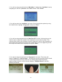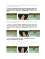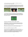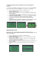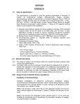
1
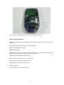
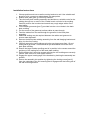
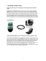
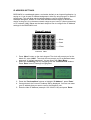
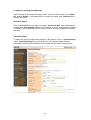
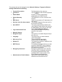
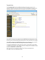
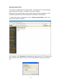
BIOPUNCH INDEX
1. YOUR NEW BIOPUNCH SYSTEM
•
•
•
Checklist
Setup Requirements
Power Requirements
2. INSTALLATION GUIDE
•
•
•
19
Introduction
Terminal Log Off/Status
User Administration
- Attendance Report
- Daily Report
- View Event Log
- Add Event Log
- View User List
- Add New User
- Departments
- User Messages
Tools
- Upgrade Firmware
- Download Report
6. TROUBLESHOOTING
•
•
•
12
Fingerprint Enrollment
Automatch vs. Pin Number Verification
Removing employees
Clocking
5. BIOPUNCH WEB UTILITY
•
•
•
8
Connecting Directly to a PC
Connecting to a Network via a Switch/Hub
IP address settings
4. ENROLLING AND REMOVING EMPLOYEES
•
•
•
•
3
Parts List
Mounting Instructions
3. NETWORK CONNECTIONS
•
•
•
2
Fingerprint problems
Network/communication problems
Frequently Asked Questions
43
1. YOUR NEW BIOPUNCH SYSTEM
Checklist
Please ensure the following items are included in the Biopunch box:
•
•
•
•
•
•
Biopunch Clocking Unit
User Manual CD
Crossover Network Cable (Black) [for connection DIRECTLY to
PC/Notebook]
Straight Network Cable (White) [for connection to network point/hub/switch]
A 12V DC Switching Power Supply (Input: 100 - 240 VAC 50/60 Hz)
1 Power Cord [according to Country Specification]
Setup Requirements
•
•
•
•
Windows 95/98/2000/NT/XP
RJ45 Cabling for Network Connectivity.
Straight Network Cable (To connect to your corporate network via
Hub/Switch)
Crossover Network Cable (To connect directly to your Computer with a
network card)
Power Requirements
•
•
A 12V DC switching power supply (provided).
Please do not share the power supply with any external devices. Electronics
are sensitive and it could interfere or damage your Biopunch unit.
2
2. INSTALLATION GUIDE
Introduction
Please ensure you have the correct tools and you are comfortable with carrying out
the installation set out below. If the unit is damaged due to the use of incorrect tools
or inferior workmanship, your guarantee will be voided. Please make use of our free
2 week telephonic support from delivery date to double check anything that you are
unsure about.
Positioning and installation considerations
In order to establish a suitable position for the clock, you will need to consider the
following:
• The clock should be positioned in an area where employee traffic can flow
freely during clocking time.
• The clock must also be positioned next to a 220V AC power plug.
• Only use switching power supply provided with unit of 12V DC, 1 Amp
capacity. If required, use an appropriate UPS (uninterrupted power supply)
with battery backup. This will ensure unit will still operate in the event of a
power failure.
• The clock will have to be connected via a network cable to a network point,
hub port or directly to a computer network card (for direct connection – see
section 3 below). You will need to consider the cable run between the clock
and the network point, hub or PC when planning the clock position.
• Ensure the clock is mounted at the correct height to allow ease of use and
correct finger positioning.
• Mounting the clock in strong sunlight may affect user visibility of the LCD.
Ensure that the LCD and LED’s are clearly visible in all lighting conditions.
The ideal height for the Biopunch clock to be mounted is 1 m 320 mm
from the floor to the bottom of the clock, as shown in the diagram
below:
3
Parts List
Part 1
Part 2
Part 3
Part 4
Part 5
Part 6
4
Part 7
Part 8
Part 9
Part 10
Part 11
5
The Figure above shows the input for power and also network cable.
Parts List Descriptions
Part 1: This shows the back of the BIOPUNCH clock and the Allen key used to unscrew the
back plate.
Part 2: Extra securing Allen cap screw for the back plate.
Part 3: Back plate once removed.
Part 4: Power Supply
Part 5: Black cross-over network cable (to connect directly to your computer), White network
cable (to connect to a hub or switch on your local network).
Part 6: Wall mounting screws (for wall plugs).
Part 7: Rubber Grommets for cut out holes if used.
Part 8: Special Allen Key for back plate screw.
Part 9: Seals for molding securing screws.
Part 10: Wall plugs.
Part 11: Securing screws for the molding.
6
Installation Instructions
1. Choose position and secure wall mounting bracket to wall. Use suitable wall
plugs for brick, concrete or plasterboard- as appropriate.
2. Ensure back plate [part 3] is correctly earthed.
3. Take the back plate molding assembly and decide on a suitable route for the
cabling through one or more of the 3 cable knock out holes in the molding.
Carefully remove the knockout and smooth any rough edges with a file or
sand paper.
4. Fit the rubber grommets [part 7] provided into the cut out holes in the back
plate molding.
5. Cut the centre of the grommet to allow cables to pass through.
6. Feed the cables from the wall through the grommet in the back plate
assembly.
7. Additional sealing may be required between the cables and grommet to
ensure water tightness.
8. Remove the back plate molding assembly from the wall hanging bracket and
align it to the front casing.
9. Carefully secure the two moldings using the securing screws [part 11] and
seals [part 9] provided. These should be pre-assembled to the rear of the
back plate molding.
10. Ensure the large weather proofing seal is in position in the recess around the
periphery of the mating face of the back plate molding.
11. Evenly tighten the 8 securing screws ensuring the two moldings are correctly
mated. Take care not to over tighten screws.
12. Engage the upper locating tags of the brackets by hooking the assembly into
position.
13. Secure the assembly into position by tightening the locking screw [part 2]
from the underside of the unit ensuring that it engages with the locking tab of
the wall mounting bracket.
7
3. NETWORK CONNECTIONS
Connecting Directly to a PC Network Card Using Crossover Network
Cable
Connecting your BIOPUNCH directly to your PC can be done using the supplied
BLACK crossover cable. Should you require a longer cable; most PC stores can
make one up for you but be sure to mention that you want a CROSSOVER Cable.
Connect the crossover cable to the network card on your PC. Plug the other end of
the crossover cable into the port located behind the BIOPUNCH clock. Once both
ends are plugged and the connection is detected you will see a green light on the
port of the BIOPUNCH clock. This means that communication between the clock and
the PC is successful. You can now proceed to the IP address settings section below.
Connecting BIOPUNCH to your PC Network (LAN) using Patch cable
Connecting your BIOPUNCH to your PC Network (LAN) via a network point, hub or
switch can be done with the supplied WHITE patch cable or a straight network cable
(Standard Network Cable). Should you require a longer cable; most PC stores can
make one up for you. Connect the patch cable to the network point or hub/switch
port. Plug the other end of the patch cable into the port located behind the
BIOPUNCH clock. Once both ends are plugged and the connection is detected you
will see a green light on the port of the BIOPUNCH clock. This means that
communication between the clock and the network point or hub/switch is successful.
You can now proceed to the IP address settings below.
8
IP ADDRESS SETTINGS
BIOPUNCH is a web-based system, and works similarly to an Internet Application. In
saying so, it has its own IP Address assignment, either by using Dynamic or Static IP
Assignment. This will allow web browsing software, such as Internet Explorer,
Netscape Navigator, Mozilla or most other standard web browsers to access the
device as long as it is in the same network range as your host PC (direct connection)
or PC network (LAN). Below are the basic steps on how to configure the IP Address
settings for the BIOPUNCH unit.
Keypad Layout
------ Menu
-------- Back
------ Enter
|
|
|
|
Previous Next
1. Press “Menu” button on the clock keypad. The clock will prompt you for the
Admin ID, enter “A999”. The clock will now prompt you for a password enter
password “1” (default password). You are now in the ‘Main Menu’.
2. Select the ‘IP Setting’ icon by navigating with the ‘Previous/next’ buttons.
Press ‘Enter’ once IP Settings is highlighted.
3. Press the ‘Previous/Next’ buttons to highlight “IP Address”, press ‘Enter’.
4. Once selected, the Current IP Address will be displayed. You can now enter
your IP address that you want to use for the Biopunch unit.
5. Enter the New IP Address (example: 192.168.001.103) and press ‘Enter’.
9
6. If successful, a “Success” message will be displayed and the green LED will
be on.
7. Press ‘Enter’ to modify other settings in the IP Settings sub menu like the
“Gateway” of your network.
8. Once you are back in the “IP Setting” sub menu, navigate using the
‘Previous/Next’ buttons until ‘Gateway’ is highlighted then press ‘Enter’.
9. The Current Default Gateway address will be displayed. You can now enter
your Default Network Gateway Address. (Example: 192.168.001.001)
10. Once entered, press ‘Enter’.If successful, a “Success” message will be
displayed and the green LED will be blinking.
11. Press the ‘Menu’ button to go back to the Administrator Menu Screen, or hit
‘Back’ twice to exit from the system.
Once the IP (Internet Protocol) configuration on the BIOPUNCH clock has been
correctly configured as explained above you can then test for connectivity by
following the following steps:
10
1. Click on the ‘Start’ button in Microsoft Windows on your host PC or any of
your PC’s on your network. Click on ‘Run’. Type in ‘CMD’ and click ‘OK’. A
MSDOS PROMPT screen will appear.
2. Type in ‘Ping’ [leave a space] and the IP address you assigned to the clock in
step 5 above e.g. ‘Ping 192.168.001.100’. Then press ENTER.
3. If connectivity is successful, you will see a message displayed 3 times on the
MSDOS screen i.e. ‘REPLY FROM 192.168.001.100: BYTES=32 time>1ms
TTL=128’.
4. This means your system is setup correctly and can now be seen over the
network or the Web Interface on the BIOPUNCH clock.
Example:
•
Standalone PC using direct connection with crossover cable: Configure the IP
address information on the PC as follows:
o Right-click on My Network Places. Then right-click Local Area
Connection and select Properties. Highlight Internet Protocol (TCP/IP)
and select properties.
o Select the bullet: Use the following IP address. Enter an IP address
e.g. 192.168.001.010
o Enter a subnet mask of 255.255.255.0
o Enter a default gateway of 192.168.001.001
o When you configure the IP address for the Biopunch clock as
described above use an address of 192.168.001.011. Use the same
subnet mask and gateway as the PC when entering this information
into the Biopunch clock.
o NOTE: If you already have information in these fields on your PC we
do not recommend you change anything. Rather contact the IT
technician who configured your system for advice.
•
PC on network: Check the IP address information by following the abovementioned steps and do the following:
o Ensure that the IP address you use for the Biopunch clock falls within
your address range e.g. if your PC address is 192.168.001.020, you
can use any IP address that reads 192.168.001.xxx.
o Xxx can be any number between 002 and 254 but CANNOT be a
number that is being used by any of your other network devices (the
number must be unique).
o You must ensure that the subnet mask and gateway addresses on the
Biopunch clock are the same as your PC addresses.
Note:
• Not all PC’s will be configured with this information (especially in a standalone environment). If you are unsure about this part of the installation
contact your PC Technician or alternatively contact our offices during the 2
week free support period.
• Not all PC networks have Default Gateways etc. If you are unsure about this
part of the installation contact your PC Technician or alternatively contact our
offices during the 2 week free support period.
• The above are examples only. Addresses may be different for your particular
environment.
• If you cannot establish communications with the Biopunch clock then refer to
the Trouble-shooting and FAQ guide at the end of this manual before phoning
for assistance.
11
4. ENROLLING AND REMOVING EMPLOYEES
ENROLLING EMPLOYEES
In order to ensure the clock gives you hassle-free service it is vital that it is
configured correctly and your employees’ fingerprints are enrolled properly. If an
employee’s fingerprint is enrolled correctly the probability of the clock rejecting their
clocking is greatly reduced. Please pay special attention to the instructions below.
Understanding the term “Fingerprint Core“
A fingerprint core is a point located within the innermost curving ridge of any given
finger found center between the tip and first crease of the finger.
It is highly recommended that the fingerprint core be big and clear for a successful
enrollment and good quality image. For this reason we recommend using a thumbprint.
Good Print
Bad Print
Make sure the fingerprint image captured is of the core of the finger presented.
12
Keypad Layout.
------ Menu
------ Back
------ Enter
|
|
Previous Next
Capturing Fingerprints (NOTE: Instruction video included on CD!)
Before carrying out this procedure we recommend using the thumb for enrollment as
it presents a larger image for capture (the images below indicate enrolling the index
finger but this is for demonstration purposes only). Having said this should the thumb
not be a viable option then other fingers can be used i.e. index finger, middle finger
and ring finger (in that order).
This clocking unit requires 5 images of the same finger for successful enrolment. This
is to try compensate for any misaligned finger placements when employees clock.
Details on how to enroll the 5 images are presented below.
To start the process, do the following at the clock:
1. Press “Menu” button on the clock keypad. The clock will prompt you for the Admin
ID, enter “A999”. The clock will now prompt you for a password enter password “1”
(default password).
13
2. You will now be presented with the “Main Menu”. Highlight the “Add User” icon by
navigating to it with the “previous” and “next” buttons. Press “Enter”.
3. You will now be in the “Add User” sub menu. Scroll through the options by using
the “next” button. Highlight “Fingerprint” and press “Enter”.
4. You will now be presented with the “New User (FP)” screen. At this point you will
need to enter a unique ID number for the employee you are about to enroll. This
number will be used by the software to link an employee’s name to the fingerprint you
are enrolling. We recommend using an ID number from one to four digits long. Enter
the unique ID number for the employee and press “Enter”.
5. You will now be presented with the “Fingerprint” sub-menu. The screen will
display “Finger 1/5 – wait for finger”. The employee should now place his/her thumb
on the sensor and ensure the entire core is centrally aligned with the sensor,
applying slight pressure, until the screen displays “Template Stored”, and then
remove your thumb.
14
6. The clock will prompt you to press "Enter". Press “Enter” to proceed with capturing
the second image of the same thumb.
7. The clock will now display “Finger 2/5 – wait for finger”. Place the same thumb
on the sensor except that this time the thumb must be slightly aligned to the left but
still ensuring the that the entire core of the thumb is presented to the sensor. Apply
slight pressure, until the screen displays “Template Stored”, and then remove your
thumb.
8. The clock will prompt you to press "Enter". Press “Enter” to proceed with capturing
the third image of the same thumb.
9. The clock will now display “Finger 3/5 – wait for finger”. Place the same thumb
on the sensor except that this time the thumb must be slightly aligned to the right but
still ensuring the that the entire core of the finger is presented to the sensor. Apply
slight pressure, until the screen displays “Template Stored”, and then remove your
thumb.
10. The clock will prompt you to press "Enter". Press “Enter” to proceed with
capturing the fourth image of the same thumb.
11. The clock will now display “Finger 4/5 – wait for finger”. Place the same thumb
on the sensor. The thumb must be centrally aligned (as in step 5 above) except that
this time the thumb must be placed slightly higher on the sensor but still ensuring that
the entire core of the thumb is presented to the sensor. Apply slight pressure, until
the screen displays “Template Stored”, and then remove your thumb.
15
12. The clock will prompt you to press "Enter". Press “Enter” to proceed with
capturing the fifth image of the same thumb.
13. The clock will now display “Finger 5/5 – wait for finger”. Place the same thumb
on the sensor. The thumb must be centrally aligned (as in step 5 above) except that
the thumb must be placed slightly lower on the sensor but still ensuring that the entire
core of the thumb is presented to the sensor. Apply slight pressure, until the screen
displays “Template Stored”, and then remove your thumb.
14. If all images are accepted, an acknowledgement message “User Added” will
appear. You have now successfully enrolled multiple images of the same thumb for
the same employee. By enrolling the thumbprint multiple times you are enabling the
system to be more forgiving if an employee doesn’t place their thumb in the exact
same position every time.
Automatch and Pin Number Verification (PNV) explained
Automatch allows your employees to clock without first having to punch in their
unique ID number on the keypad. All they need to do is present their thumb on the
sensor when clocking. This is a great feature of the clock as it requires very little
input from your employees at clocking time.
PNV requires the employee to enter their unique ID number first and then present
their thumb on the sensor before the clock will authenticate the clocking.
When to use automatch and when to use PNV?
We recommend that you use automatch as it is the easiest method for your
employees to clock. However PNV is slightly quicker when the clock authenticates a
fingerprint and it is more forgiving when it comes to bad quality fingerprints. We
suggest that you try the automatch method first and should you experience any
performance or image quality issues then disable automatch for the problem
employees (this will automatically enable PNV for that employee).
16
To enable Automatch (can be enabled at the clock or through the
software)
As mentioned above PNV is enabled by default on the clock. To enable automatch
at the clock itself (thereby disabling PNV) for an employee do the following:
1. Login onto the clock as administrator as explained above.
2. Press the “Menu” button.
3. Navigate to the “Automatch” icon using the “previous” and “next” buttons
and press “Enter”
4. The clock will prompt you to enter the employee’s unique ID number. Punch
in the number and press “Enter”.
5. The system will present you with a screen displaying “automatch enabled”.
You have now successfully enabled automatch for this employee.
6. You will need to repeat this process for each employee that requires
automatch.
7. Automatch can also be enabled per employee in the built-in software. Please
refer to the software section in this manual for further information.
REMOVING EMPLOYEES
After enrolling users into the system, you can manage them with the User
Management option under the Administrator Menu. To remove an employee from the
clock, do the following:
1. Login onto the clock as administrator as explained above.
2. Press the “Menu” button.
3. Navigate to the “User management” icon using the “previous” and “next”
buttons and press “Enter”.
4. To delete a user, press the “previous” or “next” button until “Delete User”
has been highlighted and press “Enter”.
5. Punch in the unique ID number of the employee that has to be deleted, e.g. 6
and press “Enter”.
6. Repeat this process for all employees that have to be removed from the
clock.
17
CLOCKING
•
•
•
When using automatch, employees will present their thumb on the
sensor exactly as you’ve enrolled them (see above). The employee
must keep their thumb in place until the clock gives a ‘Welcome’
message for an ‘In’ clocking or a ‘Goodbye’ message for an ‘Out’
clocking.
When using PNV, employees must first punch in their unique ID no.
and then present their thumb on the sensor as exactly as you’ve
enrolled them (see above). The employee must keep their thumb in
place until the clock gives a ‘Welcome’ message for an ‘In’ clocking or
a ‘Goodbye’ message for an ‘Out’ clocking.
See the troubleshooting section at the end of the manual for other
possible clock messages when clocking.
18
5. BIOPUNCH WEB UTILITY
BIOPUNCH comes standard with a built in Web Utility which can be viewed from any
local computer on the network via an Internet browser. It supports Internet Explorer,
Netscape Navigator, Mozilla or any other standard web browser. This allows for
remote administration.
Accessing the Web Utility
Open your web browser, e.g. Internet Explorer. In the ‘address bar’ of Internet
Explorer at the top of the page (where you usually type the address of the website
you wish to view) type in the IP Address of the BIOPUNCH clock e.g. 192.168.1.11
The login page will now appear. Click on “Secure”, highlighted in blue to login using
secure data transfer.
After selecting “Secure” login, the above screen will be displayed. To go on and login
to view the web interface of the BIOPUNCH clock, select either “Accept this
certificate permanently” or “Accept this certificate temporarily for this session”.
It is recommended that you select the “Permanently” option so that this is only done
once. Otherwise it will be necessary to go through this procedure each time one logs
in. Once the option has been selected and the “OK” button has been clicked, the Log
In page will reappear.
The log in information will be exactly the same as if you were physically accessing
the main menu at the BIOPUNCH clock.
Next to “Login ID” type in “A999” and next to “Password” type in “1”.
19
Under password you will see the “Login Level” drop down menu as shown above.
Click on the down arrow to access the menu. You will now be presented with the
following options, “Personal User”, “User Administrator”, “Network Administrator”
or “Super Administrator”.
Each login level has different restrictions which will restrict a User from accessing
certain parts of the program. It is recommended that you choose “Super
Administrator” which has no restrictions and all functions will be accessible. Once
Super Administrator has been selected you may continue to click the “Login” tab.
20
Terminal Status
After logging in under Super Administrator (Default ID: A999, password: 1). The
“Terminal Status” screen will be displayed.
This displays information of the clock such as the Model Number, Serial Number, and
Firmware Version and so on.
On the left hand side of the screen you will see all the various options divided into
groups.
“Terminal”, “User Administration”, “Access Control”, “Terminal Settings” and
“Terminal”.
Under the “Terminal” category, you will have two options available to you. “Log Off”
and “Terminal Status”. Log off will take you back to the log in screen and Terminal
Status shows the BIOPUNCH info.
21
User Administration
Attendance Report
Under User Administration, select the option listed as “Attendance Report”, by
clicking this, following screen should be displayed:
This option will give you a summary of the last 3 sets of IN/OUT clocking of any given
user.
There are 4 different searching options available to view the Attendance Report
which include “User ID”, “Department”, and “Period” or specify the “Dates To &
From”.
The information that can be viewed is “User ID” followed by “Name”, “Date”,
“Weekday” and “IN/OUT” recorded times. Moreover, you get an overview of the Total
Hours worked by any given employee on any day. This information can then be
exported to Excel or text files.
This can be done by selecting the drop down menu next to “Format”. The options
you will have available are to export as a .txt (text) file or a .csv file (excel) file
format. Once you have selected the format you want to export the report as, select
the “export” button. A save as screen will now appear. Click on save and select the
folder you wish to save the report to.
22
Daily Report
Under User Administration, select the option listed as “Daily Report”, by clicking this
following screen should be displayed:
This option will give you a summary of the first IN and the last OUT clocking of any
user.
There are 4 different searching and export options available to view the Daily Report
which include “User ID”, “Department”, and “Period” or specify the “Dates To &
From”.
The information that can be viewed is “User ID” followed by “Name”, “Date”,
“Weekday” and “First IN” & “Last OUT” & whether the user is currently INSIDE or
not represented by a black / grey dot, which depict OUT and IN respectively.
23
View Event Log
Under User Administration, the first option listed is “View Event Log”, by clicking this
following screen should be displayed:
There are 6 different searching options available to view the Event Log which include
“User Name”, “User ID”, “Department”, “Event”, “and Period” or specify the “Dates
To & From”.
The information that can be viewed is “User ID” followed by “Name”, “Department”,
“Date”, “Time”, “Event”, “Terminal” and “Remark”.
To sort the list, click on the column header, for instance, to sort by Event, click on the
column header “Event”, which is in blue, and the list will be sorted in alphabetical
order. By default, the displayed list is sorted by Date/Time.
24
Deleting Event Logs
To delete event logs, click on the drop-down menu at the bottom of the page, and
you have an option to delete ALL logs EXCEPT “none”, “this week”, “these 2
weeks”, “this Month”, or “these 2 months” records. NB: All logs will be deleted
except for the option chosen.
Click on Submit to delete the log. Once deleted, the logs are not retrievable via the
BIOPUNCH unless you have a backup copy of it on your PC.
Add Event Log
There are many times when a user forgets to clock in or clock out from their terminal.
This option is especially introduced for Administrators to make the export of the data
more accurate so that it can be easily handled by any payroll system without much
hassle.
Only User Administrators and Super Administrators have the power to add/modify an
event log, which could cause changes to the report and must be treated carefully.
The following shows you how to add an event log into the system.
25
Select “Add Event Log” under User Administration on the left of your screen, and
the above screen should be displayed.
Enter the Employee ID for whom the event is being added, and enter the Date &
Time in yyyy/mm/dd (Year, Month and Day) & hh:mm:ss (Hours, Minutes and
Seconds) formats. Select the Event (In or Out) & Terminal being added from the drop
down menu.
Click “Add” to append the event to your unit or “Reset” to cancel any changes made.
Once the Add is successfully completed, the confirmation message “Add Event Log
Successful” should appear in red.
View User List
To view the users already enrolled in the system, by fingerprint, click on “View User
List” under User Administration from the left column. The following page will be
displayed:
26
There are 4 different searching options available to view the User List which includes
“Last Name”, “First Name”, “User ID”, or “Department”.
The information that can be viewed is “User ID” followed by Last Name, First Name,
Other Name, Active, FP, SMC, PSW, A/M and IN/OUT.
Description of Information displayed:
i. Active – The Status of the User, Green – Active, Red - Inactive
ii. FP – Whether Fingerprint is an available authentication option.
iii. SMC – Whether Smart Card is an available authentication option.
iv. PSW – Whether Password / PIN is an available authentication option.
v. A/M – Whether Auto-match is an available authentication option.
vi. In/Out – Whether the user is currently In or Out of Premises.
If these descriptions are active a black dot (●) will be displayed in that specific
column. If it is inactive or not available it will be grayed out.
To Sort through the list or Manage Users
To sort the list, click on the column header, for instance, to sort by Last Name, click
on the column header “Last Name”, which is in blue, the page will refresh and the list
will be sorted in alphabetical order. By default, the displayed list is sorted by ID.
To Delete/Deactivate/Activate Users
To delete users from the system, you can select the checkboxes on the left of the ID
under User List.
If all the users need to be deactivated/deleted/activated, click the “Select All” to check
ALL boxes. To cancel the selection, click on “Deselect All”. Once selected, click the
respective buttons at the bottom of the page, as shown below.
27
Once deleted, the user will no longer be in the system and all their relevant
information will be removed from the system, so make sure you really want to delete
them before carrying out the process.
Deactivation can take place if users or employees are no longer required to use the
system for a period of time. Once you deactivate a user, the dot in the column
“Active” will appear grey. To activate them again, check the box next to their ID and
click “Activate”. This is a lot more flexible than deleting a user, since it will keep the
user in the system but just restrict access for the specified time.
To Add New Users
There are 2 ways of adding users to the system; you can either add them directly at
the web interface, or from the unit. It is however better to add the employees from the
Web Interface because this allows you to enter in the employee details like first
name, last name, etc and then add the fingerprint template at the BIOPUNCH unit
afterwards. Now let us look at how to add a user directly from the web interface.
To Add A New User:
Click on “Add New User” from the left column under “User Administration”, the
following page will be displayed:
28
Enter the User ID (unique pin number), Last Name, First Name, Other Name, and
Admin Level and enter the password in the following field. Check the relevant boxes
for the relevant Access Group, this will limit or give them access at different times
depending on the configuration made.
Select the Department for which the user works, and what level the fingerprint
security should be. It ranges from Low – Normal – High – Highest. Low security looks
the minimum matching points on the finger and decreases the probability of “failed
rates” when employees clock. High security looks at max points on the finger but it is
suggested that by default all users are set to the lowest possible security level if the
unit is to be used purely for time keeping purposes.
Should any employees still struggle to clock on the low security setting you can
enable a “lowest” security level. This can be enabled as follows:
Type this link into a web browser of your choice, i.e. Internet Explorer.
http://192.168.1.100/cgi-bin/enableLowestFPLevel.cgi
The IP address typed in above should be the IP details assigned to your BIOPUNCH
clock.
29
Select “Enable” and then click “Modify”. Red writing will appear at the top of the
page informing you that the Security Level was updated. The page will automatically
go back to the Terminal Status page when done.
Go back to “Add New User” and select “Fingerprint Security Level”. There will now
be a new security option (LOWEST) available for selection as shown below.
See troubleshooting guide for more information on solving “failed rate” problems.
30
Select the status of the user, whether they can use Auto Match or Password. Auto
match enables the employee to clock without entering a Pin Number First. Click
“Add” to add the new user.
31
Departments
This option under User Administration can be used to add new departments, modify
existing departments or delete them.
To Add a New Department:
Click on “Departments” under User Administration from the left column. Enter the
Department name and description and click “Add” to append the department to the
existing list.
To Modify Existing Departments:
Click on the Department ID (Numbers in Blue), make the changes you desire, after
which, clicking “Modify” would confirm the modification, or “Reset” will abort the
modification.
To Delete Existing Departments:
Select the check boxes of the Departments to be deleted, once selected, click
“Delete” to remove them from the list of Departments, or “Clear” to abort the deletion.
Please note deleting a Department will cause its underlying Access Groups to
be deleted too.
32
User Messages
This option can be used to send personalized messages to individual users, which
will be displayed once they have authenticated (clocked) at the BIOPUNCH unit.
To Add a New Message:
Click on “User Messages” under User Administration on the left column, the
following screen should be displayed.
Enter the User ID of the user this message is for, and enter the message in the User
Message text box.
Click “Add” to attach the message to the user’s info on the BIOPUNCH unit or
“Reset” to abort the message. Please ensure that the message does not contain
more than 21 characters per line, a maximum of 3 lines are accepted per message.
Optionally, the message can either be displayed on the LCD screen of the
BIOPUNCH or sent directly to their E-mail address, or both.
33
To delete an existing User Message:
Check the box of the relevant message, and if all need to be checked, click “Select
All”, and hit “Delete”. If the delete does not need to be made, click “Deselect All” to
uncheck all boxes.
Access Control
This model BIOPUNCH unit does not support “Access Control” and is designed as
a stand alone time keeping clock. It is not advised to set up access groups, triggers
or holidays. Any modifications of the clock for access control or triggers will void the
warranty.
Terminal Setup
To make any system configuration changes to the system, click on “Terminal Setup”
under “Terminal Settings” from the left column. All system changes that are
technically related will be available from this option for the network administrator.
34
The options that can be changed include Network Settings, Fingerprint Related
Setting & Miscellaneous Setting:
•
•
•
Terminal Description
IP Address
or
Subnet Mask
•
Default Gateway
the
DNS Server
•
Security Level (for Auto match)
•
Auto IN/OUT
•
Log Unauthorized Event
•
•
Network Camera
Weigand Output
•
Language
•
Web server Port
•
Allowed IP
•
SMTP Server
•
Emergency Password
•
Administrator's Email Address
•
The Description of the terminal
The IP Address of the terminal (Dynamic
Static)
If DHCP, it will be automatically
assigned by your DHCP server.
The address for it to be connected over
Internet.
Used to map names to IP addresses and
vice versa.
The Global Fingerprint Security level for
the clock for all users.
This option automatically switches the
user’s IN/OUT status when they clock on
the BIOPUNCH unit. Here you can also
select “Reject Repeated Event”.
This option will record every denied
access to the system.
N/A
This option is to enable Weigand output
from the unit.
This option lets you select between
various languages.
The port at which you would
communicate with BIOPUNCH.
This allows the specific IP Address to be
enabled / disabled.
For sending messages directly to e-mail,
provide a valid SMTP Server address
which does not require additional login
ID/Password verification.
Emergency passwords are for distress
situations where employees can key in
the specified password before their
individual PIN to send an alert to the
Email Address specified below.
Specify an E-mail address where
distress email should be sent to.
35
Terminal Clock
The “Terminal Clock” can be modified according to the region you are in. It is
extremely important to have the correct time set for time attendance purposes or for
reporting purposes since that’s the time the system will record for any clockings.
If the SNTP (Time server) is enabled, then the BIOPUNCH will follow the time of the
local time server, either provided by the government or other authorities in the region.
If the SNTP is disabled, the BIOPUNCH will either have to follow the time on the PC
or a time can be set for the device according to the local time settings.
To enable the BIOPUNCH to follow the time on the PC, select “On” for Auto Adjust.
To disable this auto adjust, select “Off” and the time setting will be available for users
to input the “New Date” and “New Time”.
Also, time can be set according to regional Time Zones as presented here.
Click “Set” to save any modifications made.
36
Backup System Data
The system’s configuration files can be saved. It is helpful, just in case something
goes wrong with the system, to rollback to a previous setting.
Backing up is an essential part of any computer parts or Internet Appliance; it can
provide the added security and flexibility that is needed for these devices.
To backup the system configuration, click on “Backup System Data” under Tools
from the left column of options.
Once selected, click “Download” to download the data on to the PC. The system will
then prompt to save the file in the PC, click on the specified location and save the
file.
37
Restore System Data
If changes made to the system since the previous backup caused the system to work
improperly or malfunction, you can always rollback to the previous setup by selecting
the “Restore System Data” option under Tools in the left column.
Click “Browse” to locate the specified file, once located, click “Open”.
Then click “Upload” to upload the file back into the system for the previous
configuration to take place.
Firmware Upgrade
Firmware releases will be carried out on a regular basis and will be available for
download on our website i.e.
To upgrade your unit with the latest firmware, click on “Firmware Upgrade” from the
left column under “Tools”.
38
Click “Browse” to locate the firmware (once downloaded to your machine from our
website). Click “Open” once the file has been located, and “Upload” to upload it to
your system.
You will then be prompted to upgrade the BIOPUNCH firmware. This should take a
couple of minutes.
Once upload is clicked, the system will install the new firmware and your system will
reboot automatically to let the new changes take effect.
Also from this page, the current firmware version can be seen, and the upgrade
count is also available to show you how many times the system has been upgraded,
for your reference purposes.
Download Report
The Download Report option allows for easy download of attendance reports of
employees in excel or text format.
Reports can be downloaded by various different options, as shown below.
39
Reports can either be downloaded by:
• User Name
• User ID
• Department
• Trigger
• Period
• From / To (Date yy/mm/dd)
• Format – Excel or Text (Compulsory option)
Click “Download” for the report to be downloaded to your system for payroll or other
management purposes.
40
Capture Fingerprint
The BIOPUNCH can capture a fingerprint in real time and help in analysis of why
certain fingerprints are being rejected by the unit or what is causing the rejection.
This option helps the technicians better understand the fingerprint issues and what
they can do to improve readings.
Click the “Capture Fingerprint” option under Tools from the left column, which will
display the image above, to save the image, right click on it and click “Save Target
As”, the system will then prompt to ask where to save the image and the name of the
file. Click “Save” once completed.
These images should only be used for analysis purposes.
41
Reboot
To reboot the BIOPUNCH remotely, the 'Reboot' option can be selected.
Click on the 'Reboot' button to reboot the unit.
42
6. TROUBLESHOOTING
Fingerprint Problems
1. Problem: When enrolling fingerprints or when the employee clocks a “Error bad quality” message appears.
Possible reasons:
• The employee is not keeping their thumb on the sensor long enough
or is moving the thumb while the system is scanning their image.
Ensure that the employee keeps their thumb still and waits for clock to
authenticate before moving on.
• The employee’s thumb is dirty or damaged (scarring). Clean the
thumb properly. If there is scarring on the thumb, re-enroll a different
finger using the procedures mentioned above.
• The fingerprint security level is too high. Try lowering the security level
through the software (see enrolling fingerprints in manual). If the
employee still struggles to clock enable the ‘lowest security’ level in
the software for this employee (see enrolling fingerprints in manual). If
this still does not work your final resort is to disable ‘automatch’ for this
employee. He/she will be required to punch in their ID before clocking
(see enrolling fingerprints in manual).
• Good Vs Bad captured Fingerprint Image:
A good fingerprint image is one in which the core of the fingerprint is
well-defined and easily recognizable. The core of a finger is defined as
the "point located within the inner most recurving ridge". It is normally
located in the MIDDLE of the fingerprint. It is therefore critical when
enrolling that you place the finger on the scanner where the entire
core can clearly be seen. An example of a good & bad Image is
displayed as follows:
Good Image: A reading where the whole fingerprint core can be seen
clearly.
43
Bad Image: An image where the crackles & displacement of the
fingerprint core decries it unrecognizable.
2. Problem: When enrolling fingerprints a “User exist override?” message
appears.
Possible reason:
• You are enrolling an employee with an ID number that already exists
on the clock. If you are enrolling a new employee ensure that you
select a unique ID number for the employee. Press the “back” button
to cease the override. If you are re-enrolling fingerprints for an existing
employee then press the “enter” button to proceed with the override.
3. Problem: “Access denied” message appears when clocking.
Possible Reason:
• Employee has entered the incorrect pin number (only applicable for
PNV method).
• Fingerprint being presented does not exist on the clock i.e. employee
has not been enrolled or is using the incorrect finger to clock.
44
Network/Communication Problems
1. Problem: Lights (LED’s) do not appear on PC network card, hub/switch or on
the back of the Biopunch clock (where network cable plugs in).
Possible Reason:
• Faulty cable or faulty PC network card or faulty hub/switch port. Try a
different network cable. Ensure your network card is installed and
functioning in Microsoft Windows. Try replacing your network card. Try
a different port on your hub/switch.
2. Problem: LED’s are on but still no communications.
Possible Reason:
• Network setup incorrectly. Ensure you have NO duplicate IP
addresses for your network devices. Ensure your IP addresses all fall
within the same network range. See network configuration section
above. If you still cannot solve your problem you may need to consult
an IT technician for help.
Frequently Asked Questions
1. Question: My employees hands are often very dirty, scarred and worn down
due to the nature of my business i.e. bricklayers, sand papering etc. Should I
be considering Fingerprint in my environment?
Answer: There is no doubt that the success of any fingerprint system is
dependant on decent quality fingerprints. Any time a finger is damaged or
dirty it can produce a failed reading. Whilst we believe Biopunch is one of the
most flexible fingerprint readers on the market we cannot guarantee that the
system will work seamlessly in these harsh environments.
2. Question: I’m not very technically inclined. Will I be able to install this system
myself?
Answer: The system is designed as a DIY solution. Having said this, some of
the concepts may foreign to you and may present a problem or two. We
recommend you make use of our 2 week free telephonic support offer (from
shipment date) to overcome any problems. You may also need to consider
using an IT technician if necessary.
3. Question: My employees are labourers who have not been exposed to a
technical system such as this. Will they be able to use this Biopunch clock?
Answer: The answer is yes! As long as the employee remembers which
finger he was enrolled with and places his finger in the same position (as
enrolled) every time, he will be able to clock. This is a big reason why we
enroll the same finger 5 times over in slightly different positions. This allows
the system to be more accommodating should the employee miss-align his
finger when clocking.
4. Question: Why should I purchase your Biopunch system over somebody
else’s?
Answer: Biopunch is being distributed and supported through Eco Time
Technology. Eco Time has been in the Time and Attendance Industry for 15
years and has a well proven track record. Guarantees and support will be
provided by Eco Time. You will have peace of mind that your Biopunch clock
will be well supported through a local Service Provider.
45
5. Question: Can I integrate my Biopunch system at a later stage with Time and
Attendance software that auto incorporates shift rules etc?
Answer: This is possible. Contact Eco Time Technology for further
information.
6. Question: What if my Biopunch clock is maliciously damaged by somebody.
How will this affect my warranty?
Answer: Unfortunately your warranty will not cover these instances. A typical
example is if the reader lens has been scratched which will significantly affect
the clocks ability to function properly. Should you return the unit and our
technicians detect foul play we will quote you on repairs. Please familiarise
yourself with our Terms and Conditions for clarity.
7. Question: Can I purchase more than one Biopunch clock for my business?
Answer: Yes. Although this requires a bit more technical input, it can be
done. Contact Eco Time Technology for more information.
8. Question: Can I connect a siren/bell to my Biopunch Clock?
Answer: This model is not designed to support bells/sirens. Should you
choose to modify the Biopunch clock for this purpose your warranty will be
voided.
9. Question: Can I connect a door trigger for access control to my Biopunch
Clock?
Answer: This model is not designed to support triggers for access control.
Should you choose to modify the Biopunch clock for this purpose your
warranty will be voided.
46