1
1018 - IP65 INSTRUCTION MANUAL
INTRODUCTION:
The entire staff of Meteor would like to thank you for selecting the
1018 (IP-65) LUMENATOR as your fixture of choice. We have
expended that extra effort to make sure you are more then pleased
and satisfied with your purchase.
Please check and make notice of any external cosmetic box damage
caused by transportation. Notify your dealer – he in turn will notify us.
If there is any damage – either inside the box or outside the box –
DO NOT INSTALL THE DEVICE. There is a possibility that
something may have come undone or unplugged.
Unpack the Lumenator. Inside the box – you should find:
- Protective packing
- The Lumenator
- One power cable
- One XLR cable
- Instruction manual
DESCRIPTION:
FEATURES:
- 16 BIT DIMMING
-
OVER TEMPERATURE Protection
Can set DMX Address via Controller
4, 6 or 9 DMX channels selectable for numerous
applications.
Automatic Identify Master Signal and change to
Slave mode.
Step-less RGBW COLOR mixing
Color CALIBRATE function
Equipped with 18 - 10w LEDS (4 in 1)
Switch-mode power supply – 90v-240v AC.
A qualified person must carry out the Electrical connection (to power). If the
external “flexible” cable or power cord of this fixture is damaged, it HAS to
be and will be replaced by the manufacturer or service agent or a similarly
qualified person in order to avoid hazard or electrical shock.
Make sure that the available voltage is NOT higher than stated at the end of
this instruction guide / manual.
Make sure the power cord is NEVER “crimped” or damaged by sharp edges.
If it is – replacing a cable must be done by an authorized dealer trained in
electrical repair.
Always disconnect from electrical MAINS, when the 1018 Lumenator is NOT
in use or before cleaning it. Definitely before cleaning it.
You could wind up getting a severe electrical shock.
Only handle power cord by the PLUG.
Never PULL out the plug by tugging on the power cord.
Very strong possibility of getting serious electrical shock.
NEVER LOOK DIRECTLY INTO THE LIGHT FIXTURE WHILE IT IS
POWERED UP – SENSITIVE PEOPLE MAY SUFFER FROM EPILECTIC
SHOCK (far fetched) BUT IT COULD HAPPEN.
IMPORTANT:
Damage caused by the disregard of this user manual IS NOT SUBJECT TO
WARRANTY. The DEALER is not and will not ACCEPT LIABILITY for any
resulting defects or problems caused by not following instructions.
IGNORANCE is NOT A VALID WARRANTY ISSUE.
*** PLEASE MAKE NOTE:
The power cord has been deliberately left OFF as most IP65 FIXTURES
ARE USED OUTSIDE and are usually hardwired into APPROVED
OUTSIDE WEATHER-PROOF JUNCTION BOXES.
Do not plug into standard unprotected outlet, except for test purposes.
SAFETY INSTRUCTIONS:
This lighting fixture has left our factory in perfect condition. In order to
maintain this condition and to ensure safe operation, it is absolutely
necessary for the user to follow the instructions and caution notes written in
this user manual.
This fixture falls under protection-class 1. Therefore it is essential that the
device should be grounded.
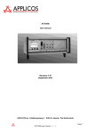
111111
MAKE SURE TO PRESS
11t11THE MIDI/ADD BUTTON AFTER
2
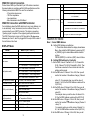
DMX-512 Control Connection
Product has a DMX Input fitted with 3-pin XLR outdoor connectors.
Screened cables in compliance with EIA-485 specifications and the
following characteristics MUST be used for connections.
- 2 Conductors plus screen
- 120 Ohm impedance
- Low capacitance
- Max. transmission rate 250 kBaud
DMX-512 Connection with DMX Terminator
For installations where the DMX cable has to run a long distance or is
in an electrically “noisy” environment, such as a Dance Venue, it is
recommended to use a DMX Terminator. This helps in preventing
“ghosting signal” corruption of the original signal by electrical noise.
The DMX Terminator is simply an XLR plug with a 120 ohm resister
between pins 2 and 3, which is plugged into the output XLR socket of
the last fixture in the chain.
Chan
CH 7: 7 Channel Mode
diCS Inst: Instant Mode: Light on / off instant
DELA: Delay Mode: Light on / light off delay
for 5 Seconds
CnFg (parameter config)
Loc Active self lock keyboard - no operation
LoCc
on the button for 30 seconds
Unloc: Deactivate self lock keyboard if NO
operation on the button for 30 seconds
StAt HoLd: Hold DMX status when no DMX signal
oFF: Light OFF when no DMX signal
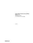
MAIN FUNCTIONS:
Axxx: Current DMX Address
A – Setting DMX Address using Buttons
DISPLAY Menu:
Menu 1
Menu 2 (conf. Menu 1)
Axxx (address)
DMX Address Setting
SPed (Auto Speed)
Auto Speed setting (00 is fastest)
at 0 - Auto Mode 0 - fade mode
Auto Mode
at 1 - Auto Mode 1: 3 color change mode
at 2 - Auto Mode 2: 7 color change mode
Ad 0 Audio Mode 0: Fade mode
Audi (audio mode)
Ad 1 Audio Mode 1: 3 color change mode
Ad 2 Audio Mode 2: 7 color change mode
Ad 3 Audio mode 3: strobe with 7 color
CoLr (show color mode)
R for Red, G for Green, B for Blue
Hr (Power on time)
Xxxx Time in hour for Power on.
CCAL (color Calibrate)
(Continued)
r
Red Calibrate Mode
g
Green Calibrate Mode
b
Blue Calibrate Mode
tEp (temperature)
xxxC Temperature in C
tEp (temperature)
xxx Temperature Calibrate
Chan CH 4: 4 Channel Mode
Chan CH 6: 6 Channel Mode
Chan CH 9: 9 Channel Mode
3
1 – Press Enter Button when the display shows Axxx
Menu, then adjust the DMX address by pressing {UP}
or {DOWN} to get to desired Base address channel
number.
PRESS {ENTER} to confirm or {ESC} return to Menu
B – Setting DMX address by Controller
1 – Set the DMX Value of Channel 5 to 10-15, Channel 6 to
20-26, Channel 7 to 30-36, Channel 8 to 40-46. Then
the fixtures connected to the controller will enter the
address setting mode.
2 - Set the DMX value of Channel 1 from 0-59, then you will
see the first number of the address change ( Channel
1
value) 10. For example: when you set the value of
channel 1 to 20, the first DMX address number will be
2 (20/10=2)
3 – Set the DMX value of Channel 2 from 0-99, then you will
see the first number of the address change (Channel 2
value)/10.
For example: when you set the value of channel 2 to
30, the first DMX address number will be 2(30/10=3)
4 - Set the DMX value of Channel 3 from 0-99, then you will
Chan
see the first number of
the address change (Channel 3
value) 10.
For example: when you set the value of channel 1 to
40, the first DMX address number will be 3(40/10=4)
5 - Set the DMX value of Channel 4 from 255, then you will
4
5 - Set the DMX value of Channel 4 from 255, then you will
see SAVE the DMX address set by the controller.
CAUTION: It won’t save the address if the ADDRESS number is OVER 512
6 – Setting the value of Channel 5-8 out of the value range
shown on the step 1 will cause the device will exit the
setting address mode.
SPEd : Auto Run Mode:
Setting Auto Run Mode
1 – Press ENTER button when Auto Menu appears, then
CnFg: PARAMETER CONFIG
Press ENTER button when menu reads CnFg. Then choose
the parameters by pressing UP or DOWN button then press
{ENTER}.
CHAn: CHOOSE THE CHANNEL MODE:
Choose the Channel mode by pressing {UP} or {DOWN}
button then press {ENTER} to confirm. Ch3 is 3 channel
mode, Ch5 is 5 channel mode, CH9 is 9 channel mode.
DiCS: CHOOSE INSTANT or DELAY Mode.
adjust the mode by pressing UP or DOWN button.
Setting Audio Run Mode
1 – Press ENTER button when Audi Menu appears, then
adjust the mode by pressing UP or DOWN button.
CoLr: Show Color Mode
1 – Press ENTER button when CoLr Menu appears, then
adjust the mode by pressing UP or DOWN button.
HR – Show the time Power ON
A – Show Time:
TECHNICAL SPECIFICATIONS:
Press ENTER Button when show Hr Menu appears, then you
will see the run time is on. When the time is over 9999 hours,
then the first number will be a hexi-decimal – for example –
A999 means 10999 hours, B999 means 11999 hours, C999
means 1299 hours. Once the first number is over 1599, the
first number will be null.
B – Clear the Time:
WATER PROOF – IP65 RATED
POWER CONSUMPTION – 120 W
IP65V POWER IN / IP65 PASS CONNECTOR
IP65 3-PIN DMX IN CABLE/ IP65 DMX 3PIN OUT
POWER SUPPLY- 100V – 240V AC 50Hz / 60 Hz
NET WEIGHT: 9lbs
SHIPPING WEIGHT: 11lbs
Press ENTER Button when show Hr Menu appears, and then
press up and down button AT the same time for 3 seconds.
Then the time will clear to 0000 simultaneously
CCAL – Color Calibrate
Press ENTER button when menu reads CCAL. Then choose
the r,g,b calibrate by pressing (UP) or (DOWN) button.
Press ENTER to enter individual colors. Adjust brightness of
the color you choose pressing (UP) or (DOWN) button.
Press ENTER to confirm or ESC to return to main menu
tEp -
Temperature Information
Press ENTER button when menu reads tEp. You will see the
temperature of the LED in unit. If there is no temperature
sensor, it will read err.
CAUTION:
The brightness WILL decrease gradually when the LED temperature
is over 120F and if it is over 150F – unit will BLACK OUT –
protection. SAVE the DMX address set by the controller.
5
6
CLEANING and MAINTENANCE:
We recommend frequent cleaning of this fixture.
Please use a soft lint-free and moistened cloth.
NEVER USE ALCOHOL or any KIND OF SOLVENTS.
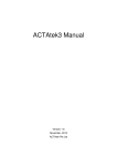
METEOR LUMENATOR
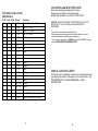
DMX PROFILE:
4 CH. 6 CH. 9 CH.
1
1
1
2
2
2
3
3
3
4
4
4
5
5
6
6
7
7
8
9
Values
0 - 255
0 - 255
0 - 255
0 - 255
0 – 255
8 - 255
0-9
10 – 19
20 – 29
30 - 39
40 - 49
50 - 59
60 - 69
70 - 79
80 - 89
90 - 95
96 - 127
128 - 159
160 - 191
192 – 255
0 - 255
0 – 255
Functions
Master Dimmer ( 0 - 100%
Red ( 0 - 100%)
Green ( 0 - 100%)
Blue ( 0 - 100%)
White
strobe (slow to fast
Null
Red
Green
Blue
White
Yellow
Magenta
Cyan
RGB
ALL ON
Macro 1
Macro 2
Macro 3
Macro 4
Speed of Macros (slow to fast)
Speed of Dimmer (fast to slow)
7
CAUTION: ALWAYS DISCONNECT POWER FROM THE FIXTURE
BEFORE ANY TYPE OF CLEANING OR MAINTENANCE IS
PERFORMED.
- There are no serviceable parts inside this unit.
- Maintenance and service operations should be carried out by only
authorized dealers or qualified service technicians.
- If you need any spare parts – PLEASE use only AUTHORIZED / factory
specified GENUINE REPLACEMENT PARTS.
INSTALLATION SAFETY:
This fixture must be installed at a vibration-free, Oscillation-free and
Fire-resistant free location. Although the unit is rated as IP65 – that
DOES NOT MEAN IT CAN BE SUBMERGED or USED
UNDERWATER. TROUBLE SHOOTING / OFTEN ASKED
QUESTIONS:
8