Download MetPak
Transcript
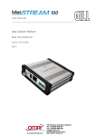
MetPak
User Manual
Doc No. 1575-PS-0001
Issue 2
Gill Instruments Limited
Saltmarsh Park,
67 Gosport Street,
Lymington,
Hampshire.
SO41 9EG
UK
Tel: +44 (0) 1590 613500
Fax: +44 (0) 1590 613501
E-mail: [email protected]
Website: www.gill.co.uk
MetPak
Doc No 1575-PS-0001 Issue 02
1
CN 4240
March 2006
MetPak
Doc No 1575-PS-0001 Issue 02
CN 4240
March 2006
Contents
Contents..............................................................................................................................................................................2
1
FOREWORD .............................................................................................................................................................3
2
INTRODUCTION .....................................................................................................................................................3
3
PRINCIPLE OF OPERATION................................................................................................................................4
3.1
WIND SPEED AND DIRECTION SENSOR ...................................................................................................................4
3.2
RADIATION SHIELD ...............................................................................................................................................5
3.3
TEMPERATURE AND RELATIVE HUMIDITY SENSOR ................................................................................................6
4
OPTIONS AND SPECIFICATION .........................................................................................................................7
4.1
OPTIONS AND PART NUMBERS AVAILABLE............................................................................................................7
4.2
SPECIFICATION ......................................................................................................................................................8
4.3
ASPIRATION SHIELD ..............................................................................................................................................9
4.4
TEMPERATURE AND HUMIDITY SENSOR .................................................................................................................9
4.5
COMPLETE ASSMEBLY ..........................................................................................................................................9
5
INSTALLATION REQUIREMENTS ...................................................................................................................10
6
INSTALLATION.....................................................................................................................................................11
6.1
INSTALLATION GUIDELINES .................................................................................................................................11
6.2
BENCH SYSTEM TEST ...........................................................................................................................................11
6.3
ELECTRICAL........................................................................................................................................................12
Cable .........................................................................................................................................................................12
Connecting the Analogue Output (Option 3 and 4) ...................................................................................................13
Connecting to an SDI-12 Interface (Option 1 and 2).................................................................................................14
Connections to WindSonic cable for MetPak options 5 and 6. ..................................................................................15
7
MECHANICAL .......................................................................................................................................................16
Orientation ................................................................................................................................................................16
Alignment...................................................................................................................................................................16
Mounting ...................................................................................................................................................................16
8
OUTPUT FORMATS..............................................................................................................................................18
8.1
GILL FORMAT– POLAR, CONTINUOUS (DEFAULT FORMAT) AVAILABLE FOR RS232 PROGRAMMING PORT. ...........18
9
ANALOGUE OUTPUTS AND OPTIONS ............................................................................................................20
9.1
ENTERING CONFIGURATION MODE (SEE SECTION 8.1 FOR MESSAGE FORMAT) ......................................................21
9.2
RETURNING TO MEASUREMENT MODE .................................................................................................................21
9.3
CHECKING THE CONFIGURATION ..........................................................................................................................21
9.4
CHANGING A SETTING .........................................................................................................................................21
9.5
POWER-UP MESSAGE...........................................................................................................................................21
9.6
ANALOGUE SETTINGS ..........................................................................................................................................22
Polar mode direction calculation ..............................................................................................................................22
Magnitude scaling .....................................................................................................................................................22
Error conditions ........................................................................................................................................................22
Disabled outputs ........................................................................................................................................................22
9.7
CONFIGURATION / DIAGNOSTIC INFORMATION ....................................................................................................23
10
METPAK SDI-12.................................................................................................................................................23
10.1
SDI-12 COMMANDS ...................................................................................................................................24
11
MAINTENANCE & FAULT-FINDING............................................................................................................25
11.1
CLEANING .......................................................................................................................................................25
11.2
SERVICING ......................................................................................................................................................25
11.3
FAULT-FINDING ...............................................................................................................................................25
11.4
RETURNING UNIT.............................................................................................................................................26
11.5
STATUS (ERROR) CODES ..................................................................................................................................26
12
TESTS...................................................................................................................................................................27
12.1
BENCH TEST ....................................................................................................................................................27
12.2
SELF-TEST (STILL AIR) FOR WINDSONIC WIND SENSOR. ..................................................................................27
12.3
CALIBRATION..................................................................................................................................................27
13
APPENDICES......................................................................................................................................................28
13.1
GLOSSARY & ABBREVIATIONS ........................................................................................................................28
13.2
GUARANTEE....................................................................................................................................................28
13.3
ELECTRICAL CONFORMITY ..............................................................................................................................29
13.4
MODEL 41003 MULTIPLATE RADIATION SHIELD MANUAL ..............................................................................30
13.5
ROTRONIC HYRGOCLIP S3 MANUAL ..................................................................................................................0
13.6
CAMPBELL CS215 TEMPERATURE AND HUMIDITY PROBE MANUAL ................................................................0
2
MetPak
1
Doc No 1575-PS-0001 Issue 02
CN 4240
March 2006
FOREWORD
Thank you for purchasing the MetPak manufactured by Gill Instruments Ltd. To achieve optimum performance we
recommend that you read the whole of this manual before proceeding with use. Do NOT remove black “rubber”
transducer caps.
Gill products are in continuous development and therefore specifications may be subject to change and design
improvements without prior notice.
The information contained in this manual remains the property of Gill Instruments and should not be copied or
reproduced for commercial gain.
2
INTRODUCTION
The Gill MetPak is a compact and lightweight multi-sensor instrument that measures the most essential weather
parameters. Gill ultrasonic technology, as used in the proven WindSonic instrument, measures wind speed and direction.
Temperature and humidity are measured using industry standard probes housed in a naturally aspirated radiation shield.
The instrument uses a rugged U-bolt mounting clamp that attaches to any vertical pipe up to 50mm diameter.
The instrument can be supplied with either a digital SDI-12 output or a four channel analogue output option, suitable to
interface to industry standard data loggers. Low power consumption enables the instrument to be used in remote
locations where power is at a premium. An electrical junction box is fitted to the mounting bracket allowing convenient
termination of all electrical cables.
3
MetPak
Doc No 1575-PS-0001 Issue 02
3
PRINCIPLE OF OPERATION
3.1
Wind Speed and Direction Sensor
CN 4240
March 2006
The MetPak uses the WindSonic wind speed and direction sensor. WindSonic measures the times taken for an
ultrasonic pulse of sound to travel from the North transducer to the South transducer, and compares it with the time for a
pulse to travel from S to N transducer. Likewise times are compared between West and East, and E and W transducer.
If, for example, a North wind is blowing, then the time taken for the pulse to travel from N to S will be faster than from
S to N, whereas the W to E, and E to W times will be the same. The wind speed and direction can then be calculated
from the differences in the times of flight on each axis. This calculation is independent of factors such as temperature.
Figure 1 Time of Flight details
4
MetPak
Doc No 1575-PS-0001 Issue 02
CN 4240
March 2006
Figure 2 Compass Points
3.2
Radiation Shield
The Multi-Plate Radiation Shield protects temperature and relative humidity sensors from error-producing solar
radiation and precipitation. This shield relies on a combination of plate geometry, material and natural ventilation to
provide effective shielding
5
MetPak
3.3
Doc No 1575-PS-0001 Issue 02
CN 4240
March 2006
Temperature and Relative Humidity Sensor
Two types of temperature and humidity probes are available dependant on the option ordered.
Campbell CS215 temperature and relative humidity probe.
The CS215 probe utilises a novel single chip element that incorporates both a temperature and RH sensor. Each element
is individually calibrated with the calibration corrections stored on chip. The element is easily changed in the field.
Replacement of the element effectively fully recalibrates the probe both for temperature and humidity thus minimising
downtime and calibration costs.
Low power electronics within the CS215 controls the measurement made by the sensor element, applies temperature and
linearization corrections to the readings and presents the data via an SDI-12 compatible interface to a datalogger.
The probe is fitted with a custom-made, yet low-cost sintered plastic filter to minimise the effects of dust and dirt on the
sensor. The filter is lightweight and hydrophobic thereby minimising the effect of the time response of the sensor.
The probe housing is designed to withstand permanent exposure to all weathers and to fit into a range of radiation
shields including lower cost compact shields.
Rotronic HygroClip.
The HygroClip modules are complete instruments, with integrated temperature compensation and highly flexible power
requirements. Calibration data is maintained within the integrated electronics. It provides linear analogue output signals
for % rh and °C.
Fig 3 Position of Temperature and Relative
Humidity Probe in the Radiation Shield
6
MetPak
Doc No 1575-PS-0001 Issue 02
4
OPTIONS AND SPECIFICATION
4.1
Options and Part Numbers Available
Product and Part
No.
Option 1
CN 4240
March 2006
Description
MetPak
Wind speed, wind direction, temperature & humidity, with SDI-12
output. White WindSonic sensor mounted on a six-plate aspiration
shield, fitted with Campbell Scientific CS215 Temperature and
Humidity probe. Complete with mounting bracket and handbook.
1575-PK-001
Option 2
MetPak
White WindSonic Windspeed & direction sensor with SDI-12 output,
mounted on a six plate aspiration shield.Customer to fit temperature
and humidity sensor of their choice up to 15mm dia.
Complete with mounting bracket and handbook.
1575-PK-002
Option 3
MetPak
Wind speed, wind direction, temperature & humidity, with analogue
output. White WindSonic sensor mounted on a six-plate aspiration
shield, fitted with Rotronic HygroClip S3 Temperature and Humidity
probe. Complete with mounting bracket and handbook.
.
1575-PK-003
Option 4
MetPak
White WindSonic Windspeed & direction sensor with analogue output,
mounted on a six plate aspiration shield. Customer to fit temperature
and humidity sensor of their choice up to 15mm dia.
Complete with mounting bracket and handbook.
1575-PK-004
Option 5
WindSonic for MetPak
White WindSonicWindspeed & Direction, sensor fitted with 1 meter of
cable and aspiration shield mounting adaptor and SDI -12 output.
Distributor to mount on their own aspiration shield and fit their own
probe.
1575-PK-005
7
MetPak
Doc No 1575-PS-0001 Issue 02
Option 6
WindSonic for MetPak
CN 4240
March 2006
White WindSonicWindspeed & Direction, sensor fitted with cable and
aspiration shield mounting adaptor and analogue output. Distributor to
mount on their own aspiration shield and fit their own probe.
1575-PK-006
4.2
Specification
Wind Sensor
Output
Units of measure
Output frequency
Parameters
or
Wind Speed
Range
Accuracy
Resolution
Wind Direction
Range
Accuracy
Resolution
Output formats
0-5V
Data Logger
Anemometer status
Environmental
Moisture protection
Temperature
Humidity
EMC
Standards
Metres/second (m/s),
Knots, Miles per hour (mph),
Kilometres per hour (kph),
Feet per minute (fpm)
1, 2, or 4 outputs per second
Digital
Analogue
Polar - Speed and Direction Polar - Speed and Direction
UV - 2 axis, signed Speed
Tunnel - U Speed and U Direction
0 – 60 m/s
± 2% (12m/s)
0.01 m/s
0 – 30m/s, 0 – 50m/s, 0 – 60m/s,
± 2% (12m/s)
0.01 m/s
0 - 359°
0 - 359°
or 0 - 539° (Wraparound mode)
±3° (20m/s)
1°
± 3° (20m/s)
1°
± 1% of full scale N.B. Analogue output impedance = 1KΩ
SDI-12 V1.3
Status OK and Error codes included as part of output message from
RS232 programming port.
IP65
Operating -35°C to +70°C Storage -40°C to +80°C
Operating <5% to 100%
EN 61000-6 - 3 (Emissions)
EN 61000-6 - 2 (Immunity)
Manufactured within ISO9001: 2000 quality system
8
MetPak
4.3
Doc No 1575-PS-0001 Issue 02
CN 4240
March 2006
Aspiration Shield
Secification for model 41003 is contained in appendix 13.4
4.4
Temperature and Humidity Sensor
Specification for the CS215 and HygroClip,temperature and relative humidity are contained in appendices 13.5 and 13.6
4.5
Complete Assmebly
Material:White thermoplastic UV-stabalized for long term weather resistance. Gloss white painted aluminium mounting bracket
(with moulded plastic V-block and satinless steel U-bolt) which allows it to be attached to a vertical pipe of any diameter
between 25mm and 50mm.
Power Requirement:Option 1
6-16Vdc @ 22mA typical
Option 3
10-28Vdc @ 28mA typical
Power requirements for the other options are dependant on temperature and relative humidity probes fitted. Refere to
manuals in appendices 13.5 and 13.6.
Size and Weight:Size
Weight
142mm dia x 380mm height (instrument)
1.1kg (including bracket)
For delivery the MetPak is contained in custom designed packaging. All the packaging should be retained for use if the
unit has to be returned at any time.
9
MetPak
Doc No 1575-PS-0001 Issue 02
CN 4240
March 2006
5 INSTALLATION REQUIREMENTS
Host system
Access to the RS232 output from the MetPak is provided for programming and fault detection via a
socket in the junction box. This can be connected to a PC fitted with a RS232 interface, and a suitable
Terminal Emulation software package. (For example Hyperterminal for Windows™ 9x, Windows™
2000 and XP or Terminal for Windows™ 3.n will normally be available on your PC.) WindCom is
available from the Gill website.
Equipment with input/output compatibility to the WindSonic Option selected.
For example, Chart recorder or Data logger, using the WindSonic Analogue output or SDI-12 output.
Cable
- To connect between the MetPak and the host system
See Section 7.3 Cable type for cable specification.
There are restrictions on the maximum cable lengths for correct operation.
The cable should be routed up the inside of the mounting tube.
Mounting Pipe
Mounting fits vertical pipe 25-50mm (1-2in) diameter.
See Figure 3 in section 7.4 Alignment & Mounting Details
For non-hostile environments, Aluminium tube can be used.
For hostile environments, you should select a material suitable for the intended environment. For
example, stainless steel 316 for marine use.
10
MetPak
6
Doc No 1575-PS-0001 Issue 02
CN 4240
March 2006
INSTALLATION
Do NOT remove the black “rubber” transducer caps. Warranty is void if the coloured security seal is damaged or
removed.
6.1
Installation Guidelines
The MetPak has been designed to meet and exceed the stringent standards listed in its specification.
As with any sophisticated electronics, good engineering practice should be followed to ensure correct operation.
•
Always check the installation to ensure the MetPak is not affected by other equipment operating locally, which
may not conform to current standards, e.g. radio/radar transmitters, boat engines, generators etc.
Guidelines –
o Avoid mounting in the plane of any radar scanner – a vertical separation of at least 2m should be
achieved.
o Radio transmitting antennas, the following minimum separations (all round) are suggested
VHF IMM – 1m
MF/HF – 5m
Satcom – 5m (avoid likely lines of sight)
•
Use cables recommended by Gill. If cables are cut and re-connected incorrectly (perhaps in a junction box) then
EMC performance may be compromised if cable screen integrity is not maintained.
•
Earth loops should not be created – wire the system in accordance with the installation guidelines.
•
Ensure the power supply operates to the MetPak specification at all times.
Avoid turbulence caused by surrounding structures that will affect the accuracy of the sensors such as trees, masts and
buildings. The WMO make the following recommendations:
•
6.2
The standard exposure of wind instruments over level open terrain is 10m above the ground. Open terrain is
defined as an area where the distance between the sensor and any obstruction is at least 10 times the height of the
obstruction.
Bench system test
Note : Prior to physically mounting the MetPak in its final location, we strongly recommend that a
bench system test is carried out to confirm the system is configured correctly, is fully functional and
electrically compatible with the selected host system and cabling (preferably utilising the final cable
length). The required data format, units, output rate, and other options should also all be set up at
this stage.
11
MetPak
6.3
Doc No 1575-PS-0001 Issue 02
CN 4240
March 2006
Electrical
Cable
Cable type
Generic description – Twisted pairs with drain wire, screened with aluminised tape,
with an overall PVC sheath. Wire size 7/0.2mm (24 AWG)
The table shows some suitable manufacturers’ references; other manufacturers’ equivalents can be used.
Application
No. of pairs
Analogue
4
SDI-12
2
Gill ref.
026-03156
-
Belden ref.
9728
Batt
electronics ref.
91199
9729
-
Cable length
The maximum cable length is dependent on the chosen communication.
The table shows the typical maximum lengths at the given baud rates, using the recommended cable. If any problems of
data corruption etc are experienced, then a slower baud rate should be used. Alternatively, a thicker or higher
specification cable can be tried.
WindSonic Option
Communication format
Baud rate
Max. cable length
Option 3 and 4
Analogue – Voltage o/p
N/A
6.5 m (20 ft)
Option 1 and 2
SDI-12
1200
90m (300ft)
Power supply
The MetPak requires a DC supply of between 9 –16vdc @ 22ma typical if fitted with a Campbell CS215
temperature and relative humidity probe or 10-28vdc @ 28ma typical if fitted with a Rotronic HygroClip S3
probe.
12
MetPak
Doc No 1575-PS-0001 Issue 02
CN 4240
March 2006
Connecting the Analogue Output (Option 3 and 4)
Remove junction box lid.
Analogue output wind.
TB3 Junction Box
Data logger or
Chart recorder
10 Way Terminal Block
Signal names
Terminal
nos.
Cable – 5 twisted pairs
Signal names
Analogue Channel 1
Wind Speed
7
Analogue Channel 1
Analogue Channel 2
8
Analogue Channel 2
Signal Ground
3
Signal Ground
Do NOT connect
at this end
N/A
V supply +
9
+
DC Power supply
V supply -
10
–
10-28 Vdc
Wind Direction
Screen and drain wires
Chassis ground
Note: SW1 must be in open position.
Analogue outputs for temperature and relative humidity
TB4 Junction Box
6 Way Terminal Block
Data logger or
Chart recorder
Signal names
Terminal
nos.
Signal names
Temp
4
Temp
R/H
5
R/H
13
MetPak
Doc No 1575-PS-0001 Issue 02
TB1
CN 4240
March 2006
TB3
Connections from WindSonic
Outputs to Customer Equipment
Connections from Rotronic
Temperature and Relative Humidity
Sensor
TB2
TB4
Connecting to an SDI-12 Interface (Option 1 and 2)
TB 3 Junction Box
Data logger or
Chart recorder
10 Way Terminal Block
Signal names
Signal names
Signal GND
3
V-
10
GND
V+
9
+V (9-16Vdc)
TXD-
1
RXD-
2
Serial Data Line
Note: SW1 must be in closed position for SDI-12 option. If you wish to use RS232 programming port then SW1 must be
in open position and only external links between TXD- and RXD- must be temporarily removed.
TB1
TB3
Connections from WindSonic
Ouputs to Customer
Equipment
Connections from Campbell
SDI12 Temperature and
Relative Humidity Sensor
TB2
TB4
14
MetPak
Doc No 1575-PS-0001 Issue 02
CN 4240
March 2006
Connections to WindSonic cable for MetPak options 5 and 6.
MetPak Option 5 SDI-12
Colour
Function
Orange
V+
Orange/White
V-
Green
Signal Ground
Blue/White
RX-
Blue
TX-
Drain Wire
Screen
+ 9-16Vdc
GND
Serial Dataline
Cable Screen
MetPak Option 6 Analogue
Colour
Function
Orange
V+
+V (10-28Vdc)
Orange/White
V-
-V
Green
Signal Ground
Brown
Analogue 1
Brown/White
Analogue 2
Blue
TX-
Blue/White
RX-
SIG Ground
Analogue Voltage Output
Programming output
15
MetPak
7
Doc No 1575-PS-0001 Issue 02
CN 4240
March 2006
MECHANICAL
Orientation
Normally the MetPak is mounted on a vertical pole, ensuring a horizontal Measuring Plane.
See Figure 3 Alignment & Mounting details
For indoor use the unit may be mounted with the Measurement Plane set to any required orientation.
Alignment
The MetPak should be aligned to point to North, or any other reference direction –for example, the bow of a boat.
There are two arrows, a coloured rectangle, and an alignment notch to aid alignment.
See Figure 3 Alignment & Mounting Details
Note : It is usually simpler to work first with a compass at ground level and identify a suitable landmark and its bearing.
Mounting
Pass the cable through the pole.
Note: the customer must fit appropriate strain relief to the cable.
It is the responsibility of the customer to ensure that the MetPak is mounted in a position clear of any structure which
may obstruct the airflow or induce turbulence.
Do NOT mount the MetPak in close proximity of high powered radar or radio transmitters. A site survey may be
required if there is any doubt about the strength of external electrical noise.
Temperature ans Humidity Probes should be mounted inside of the Radiation Shield as shown in Fig 3 section 3.3.
16
MetPak
Doc No 1575-PS-0001 Issue 02
CN 4240
Figure 4 Alignment & Mounting details
17
March 2006
MetPak
8
Doc No 1575-PS-0001 Issue 02
CN 4240
March 2006
OUTPUT FORMATS
On applying power to the MetPak, it will provide measurements in one of the following formats:
SDI-12 (Polled) – See section 10
Analogue Voltage output see section 9
An RS232 port is located inside of the junction box to enable changes to be made to the factory settings or for fault
diagnostics. You will need to connect a PC to the RS232 programming port. You can communicate with the anemometer
using the free Gill WindCom software or using Hyperterminal. Instructions for using Hyperterminal are given below.
Configuring Hyperterminal
1.
2.
3.
4.
5.
6.
Note – Other terminal emulators are configured in a very similar way.
Decide on an available Com port that you want to use (Usually Com1).
Run Hypertrm.exe (Typically accessed via Start Programs Accessories Hyperterminal)
Create a New Connection (File New Connection)
Enter a Name (eg WindSonic 1) .
Change ‘Connect Using’ to ‘Direct to Com 1’ (or other Com port as required)
Adjust the Port settings to match WindSonic settings. WindSonic default settings are :
Bits per second 9600
Data bits 8
Parity None
Stop bits 1
Flow Control (Handshaking) None
Example of message format:
Q, 229, 002.74, M, 00,
06
See Section 10 Configuring if you need to change WindSonic settings.
This RS232 programming port will default to Gill – Polar – Continuous. Details are available in section 8.1, this allows
changes to the analogue output factory setting.
8.1
Gill format– Polar, Continuous (Default format) available for RS232
programming port.
<STX>Q, 229, 002.74, M, 00, <ETX> 06
WindSonic
node address
Wind
direction
Wind
speed
Units
Status
Where:
<STX>
WindSonic node address
Wind direction
Wind speed
Units
Status
=
=
=
=
=
=
<ETX>
Checksum
=
=
Start of string character (ASCII value 2)
Unit identifier
Wind Direction
Wind Speed
Units of measure (knots, m/s etc)
Anemometer status code (see Section 12.5
for further details)
End of string character (ASCII value 3)
This is the EXCLUSIVE – OR of the bytes
between (and not including) the <STX>
and <ETX> characters.
18
Check
sum
MetPak
Doc No 1575-PS-0001 Issue 02
CN 4240
March 2006
WindSonic node address
The default setting is ‘Q’ do not change this.
Wind direction
Indicated in degrees, from 0 to 359°, with respect to the WindSonic North marker.
In fixed field mode and when the wind speed is below 0.05 metres/sec, the direction will not be calculated, but the last
calculated direction above 0.05 m/s will be output.
Wind speed and units
Shows the Wind Speed in the Measurement Plane (See Figure 3 Alignment & Mounting details) in one of the following
units:
Units
Identifier
Metres per second (default)
Knots
Miles per hour
Kilometres per hour
Feet per minute
M
N
P
K
F
Status
This indicates either
or
Correct operation Code 00
Error codes
See Section 12.5 for explanation of codes.
Checksum
This enables the host system to check that the data has been correctly received. This is the EXCLUSIVE – OR of the
bytes between (and not including) the <STX> and <ETX> characters.
Output rate (not displayed)
The WindSonic samples continuously and delivers wind information at 1 (default setting), 2, or 4 outputs / second.
19
MetPak
9
Doc No 1575-PS-0001 Issue 02
CN 4240
March 2006
ANALOGUE OUTPUTS AND OPTIONS
Note : Analogue outputs are only available from MetPak Option 4 and 6..
Voltage output
The WindSonic in MetPak is default Voltage (0 – 5 V) representing wind speeds between 0-60m/sec.
The HygroClip S3 humiduty and temperature sensor applied with MetPak option 3 only has a voltage output. If the
customer fit his own temperature and humidity probe with a current output the the mode of the Windsonic output can be
changed to suit.
Important :
1. When using the current outputs, the load resistance between the Analogue outputs (TB3-8 and 9) and Signal
Ground must be <= 250 ohms, including cable resistance.
This is to ensure that the voltage levels do not exceed 5V.
2. The current outputs must be returned to Signal Ground (TB3-3).
Polar and Tunnel modes
If the WindSonic is configured in Gill Polar mode then the analogue outputs will be in Polar mode.
Polar mode direction wraparound
The Wind Direction in Polar mode can be configured for either Standard (0 - 359°) or Wraparound (0 - 539°) options. If
the Standard mode is used with a chart recorder, large swings of the recorder pen will be experienced each time the wind
direction passes between 0 and 359°. Using the Wraparound mode, when the wind first changes from 0° to 359°, there
will be a step change on the output, but after this first time the output will change smoothly each time the wind passes
through 360°. (Similarly, the first time the wind veers from 539° to 180°, there will be a step change, after which the
output will change smoothly).
Wind direction
(degrees)
Voltage output (V)
Standard
0
180
360
540
0
2.5
5.0
n/a
Current output (mA)
Wraparound
0
1.67
3.33
5.0
Standard
Wraparound
4.00
12.00
20.00
n/a
4.00
9.33
14.67
20.00
Low wind speeds in polar mode
Whilst the wind speed is below 0.05 metres/sec, the wind direction will not be calculated.
In CSV mode, the Channel 2 output will switch between 0 and 5V (or 4 and 20mA) at the output rate selected.
In fixed field mode, the last valid direction will be output until a new value can be calculated.
Wind Speed scaling
The Wind Speed output can be configured such that full-scale output represents 30, 50 or 60 metres/sec.
In all cases zero Wind Speed is represented by 0V or 4mA.
Tunnel mode
When configured in Tunnel mode, Channel 1 output represents the wind speed along the U axis (South – North) scaled
as described above.
Channel 2 gives the direction of the wind along the U axis, where a –U vector (= wind from the N direction) is
represented by 0V (or 4mA), and a +U vector is represented by 5V (or 20mA).
Configuring Analogue outputs
WindCom may be used to change the factory default settings to configure WindSonic, alternatively, the user may elect
to use another terminal emulator package.This section describes the commands used to change User and
Communications settings.
20
MetPak
9.1
Doc No 1575-PS-0001 Issue 02
CN 4240
March 2006
Entering Configuration mode (see section 8.1 for message format)
From Continuous mode
From Polled mode
* <N>
*
where <N> is the Unit identifier
The WindSonic responds with a CONFIGURATION MODE message, stops reporting wind measurements, and waits
for a command (as detailed below).
9.2
Returning to Measurement mode
Q
ENTER
The WindSonic responds with wind measurements immediately when in Continuous mode,
or on receipt of a Poll signal when in Polled mode.
9.3
Checking the configuration
We recommend that, as a standard procedure, you use this command prior to, and after, changing any settings. It shows
the current settings for all the alterable settings.
*
D
3 ENTER
The WindSonic responds with the default settings shown below:
M2, U1, O1, L1, P1, B3, F1, H1, NQ, E1, T1, S3, C2
We suggest you note down the settings, so that you can easily return to them.
Return to measurement mode
Q
ENTER
All of these settings are explained in the following sections.
9.4
Changing a setting
To change a setting, refer to the sections below, and enter the command of the new setting required, followed by
ENTER . If successful, the new setting will be sent as a message by the WindSonic.
For example, to change the message format to NMEA, enter
M 5
ENTER
The WindSonic will reply M5 . When the unit is returned to the Measurement mode, it will be in NMEA format.
Note : The factory-set (default) settings are shown in bold in the following sections.
9.5
Power-up Message
Item
Power –up message
Options
Command
ON
OFF
H1
H2
If the power up message is On, then a message similar to that below is output,
whenever the unit goes into Measurement mode (ie. when power is first applied to
the unit, or unit returns to Measurement mode from Configuration mode).
WINDSONIC (Gill Instruments Ltd)
FIRMWARE: 2231 - 102
RS232 (CFG)
RS 232(Auto)
CHECKSUM ROM 9F5E 9F5E *PASS*
CHECKSUM FAC 04F4 04F4 *PASS*
CHECKSUM ENG 0824 0824 *PASS*
CHECKSUM CAL DFBF DFBF *PASS*
If any of these checksums fail, the word PASS will be replaced by FAIL and the unit
will use its default settings. If the checksum repeatedly fails after power on – contact
your supplier.
NOTE: The exact message above will vary.
21
MetPak
9.6
Doc No 1575-PS-0001 Issue 02
CN 4240
March 2006
Analogue settings
The following commands are only valid for the MetPak Options 4 and 6
Item
Voltage or Current
output
Analogue
range
Analogue
Wraparound
Options
Command
0 - 5 Volt
4 – 20 mA
T1
T2
0 – 30 metres per second
0 – 50 metres per second
0 – 60 metres per second
Analogue output disabled
S3
S5
S6
S9
Wrap around
0 – 539°
Normal
0 - 359°
C1
C2
Where:
Analogue range
Analogue wraparound
Voltage or current output
=
=
=
Customer selected range
Chart recorder facility
Output type
Polar mode direction calculation
The system will not calculate a wind direction when the measured velocity falls below 0.05m/s. When configured for
fixed field mode the direction output will hold the last setting until a new direction can be calculated. If the unit is in
CSV mode, the output will switch between 0 and 5V (or 4 to 20mA) at the output rate selected.
Magnitude scaling
The magnitude output can be scaled such that the full scale output represents either 30, 50 or
60ms-1.
Error conditions
If a valid wind measurement cannot be calculated (for example all paths blocked), the outputs 1 and 2 will switch
between 0 and 5V ( or 4 to 20mA) at the output rate selected.
Disabled outputs
If the analogue outputs are not required, they can be disabled (Command S9).
22
MetPak
9.7
Doc No 1575-PS-0001 Issue 02
CN 4240
March 2006
Configuration / Diagnostic Information
Each of these commands causes a response from the WindSonic.
Item
Command
D1
Type and serial No.
Response
TYPE: Y
SERIAL NO.: 012345
Software version
D2
FIRMWARE: 2231-102
Unit configuration
D3
M2,U1,O1,L1,P1,B3,F1,H1,NA,E3,
D4
EXP MOD ID: 0
Analogue ID (if present)
D4 = 0 (No Analogue outputs)
D4 = 1 (Analogue outputs enabled)
Self test
10
D6
See Section 0
12.2
Self-Test (Still Air)
METPAK SDI-12
WindSonic – Refer to SDI-12 Commands & Message Format
CS215 – Refer to Campbell Scientific User Guide
It is only possible to use SDI-12 commands to program the wind, temperature and humidity sensors. Typical output for
wind data is shown in Gill output message format.
WindSonic default mode identity. 0
CS215 default mode identity. 1 (Note Campbell probe factory default is normally set to 0, to avoid conflict default has
been set to 1, this applies to configurations preset by Gill and also by customers who fit their own Campbell probe.)
23
MetPak
10.1
Doc No 1575-PS-0001 Issue 02
CN 4240
March 2006
SDI-12 COMMANDS
SDI-12 configured units comply with SDI-12 Interface Standard V1.3
We advise that you download the full SDI-12 specification from www.sdi-12.org
All other commands not defined below respond with a ‘zero data values ready’ response.
All units of measurement are in metres per second. This cannot be re-scaled.
Name
Continuous Measurement
(Polar)
Continuous Measurement
(UV)
Continuous Measurement
with CRC (Polar)
Continuous Measurement
with CRC (UV)
Command
aR0!
Gill Output
a<dir><mag><status><CR><LF>
aR1!
a<U><V><status><CR><LF>
aRC0!
a<dir><mag><status><CRC><CR><LF>
aRC1!
a<U><V><status><CRC><CR><LF>
Start Measurement
(Polar)
Send Data
Start Measurement (UV)
Send Data
Start Measurement with
CRC (Polar)
Send Data
Start Measurement with
CRC (UV)
Send Data
aM!
a0003
aD0!
aM1!
aD0!
aMC!
a<dir><mag><status><CR><LF>
a0003
a<U><V><status><CR><LF>
a0003
aD0!
aMC1!
a<dir><mag><status><CRC><CR><LF>
a0003
aD0!
a<U><V><status><CRC><CR><LF>
a!
aI!
aAb!
?!
aXLPM!
aXHPM!
a<CR>< LF>
a13GillInst 1405 SDI v101 <sn><CR><LF>
b<CR><LF>
a<CR><LF>
0LP<CR><LF>
0HP<CR><LF>
Acknowledge Active
Send Identification
Change Address
Address Query
Measurement on demand
Continuous Reading
Default operating mode aXHPM!
Gill Output Message Format
a13GillInst 1405 SDIv***
SDI-12
address
SDI-12
version
Gill
Model No
*** Software Version may change
24
Gill WindSonic
Software Version
MetPak
Doc No 1575-PS-0001 Issue 02
CN 4240
11
MAINTENANCE & FAULT-FINDING
11.1
Cleaning
March 2006
If there is any build up of deposit on the unit, it should be gently cleaned with a cloth moistened with soft detergent.
Solvents should not be used, and care should be taken to avoid scratching any surfaces. The unit must be allowed to
defrost naturally after being exposed to snow or icy conditions, do NOT attempt to remove ice or snow with a tool.
Do NOT remove black “rubber” transducer caps.
11.2
Servicing
There are no moving parts or user-serviceable parts requiring routine maintenance in the WindSonic wind sensor fitted
to MetPak.
Opening the WindSonic unit or breaking the security seal will void the warranty and the calibration.
In the event of failure, prior to returning the unit to your authorised Gill distributor, it is recommended that :
1. All cables and connectors are checked for continuity, bad contacts, corrosion etc.
2. A bench test is carried out as described in Section 12.1.
3. You contact your supplier for advice
For future service or maintenance of the temperature and humidity sensors please refer to appandix 13.5 or 13.6 of this
manual.
11.3
Fault-finding
Applicable to WindSonic only.
Symptom
Solution
No output
Check DC power to WindSonic, cable and connections.
Check comms settings of WindSonic (as detailed in Section
10) and host system match, including correct Com port
Check unit is in Continuous mode
Check that in-line communication devices are wired correctly.
NOTE: It is usual for Anemometer TX + to be connected to
converter device RX +
Corrupted output
Check comms settings of WindSonic and host system match.
Try a slower baud rate.
Check cable lengths and type of cable.
One way
communication
Check WindSonic and host system are both set to the same
protocol RS232, RS422, or RS485.
Check wiring is in accordance with the manual.
Failed / Incorrect
WindSonic ouput, data
invalid flag
Check that transducer path is not blocked
25
MetPak
11.4
Doc No 1575-PS-0001 Issue 02
CN 4240
March 2006
Returning unit
If the unit has to be returned, it should be carefully packed in the original packaging and returned to your authorised Gill
distributor, with a full description of the fault condition.
11.5
Status (error) codes
The Status code is sent as part of each wind measurement message. These can be observed on the RS232 programming
port inside of the junction box.
Code
Status
Condition
00
01
02
04
08
09
10
OK
Axis 1 failed
Axis 2 failed
Axis 1 and 2 failed
NVM error
ROM error
System gain at
maximum
-
Sufficient samples in average period
Insufficient samples in average period on U axis
Insufficient samples in average period on V axis
Insufficient samples in average period on both axes
NVM checksum failed
ROM checksum failed
Wind velocity reported could be in error
A
V
NMEA data valid
NMEA data invalid
26
MetPak
Doc No 1575-PS-0001 Issue 02
12
TESTS
12.1
Bench test
CN 4240
March 2006
1.
Couple the MatPak to the host system and power supply, using a known working test cable.
2.
Check that the unit is correctly configured by going into Configuration mode and using D3 See Section 9.3
Checking the configuration.
Check for normal output data, and that the Status Code is OK – 00
If the status code is other than 00, refer to Section 11.5 Status (error) codes.
Use an office fan or similar to check that the unit is sensing wind, turning the unit to simulate changing wind
direction and to check that both axes are functioning. The fan will also give output changes from the temperature
and relative humidity sensor.
Note that this a quick functional test.
Use the office fan to check the temperature and humidity sensor output.
3.
4.
5.
6.
7.
12.2
Self-Test (Still Air) for WindSonic wind sensor.
This test checks Alignment, Gain, Checksums and can be performed from the RS232 port inside of the junction box.
Alignment tests : The unit performs a transducer geometry check and compares the result with its factory setting.
Gain tests : The unit performs a check of its operating gain against its factory setting.
Checksum tests : The unit performs a check of its program and data memory.
Important This test is a stringent laboratory test which will only be passed if carried out under still air conditions at
room temperature (17-23˚C). NOTE: Option 4 SDI-12 units must be in Gill mode for the self test to function (see Section
11) .
1. Place a cardboard box over the WindSonic sensor.
2.
Go into Configuration Mode * ENTER .
3.
Carry out the Self-test by entering D
6 ENTER .
A message similar to that shown below will be generated :
ALIGNMENT LIMITS:0D59,0CF5
ALIGNMENT U:OD15 *PASS*
ALIGNMENT V:OD16 *PASS*
GAIN 0:0001 *PASS*
GAIN 1:0001 *PASS*
GAIN 2:0001 *PASS*
GAIN 3:0001 *PASS*
CHECKSUM ROM:AB7D AB7D *PASS*
CHECKSUM FAC:04F4 04F4 *PASS*
CHECKSUM ENG:082A 082A *PASS*
CHECKSUM CAL:A9C1 A9C1 *PASS*
For each of the Alignment and Gain tests a Pass or Refer to Manual message is generated.
For each of the Checksum tests a Pass or Fail message is generated.
4.
If any of the tests fail, contact your supplier.
If a “refer to manual” message appears please see Section 12.3 Fault Finding.
Note that it will only pass if the specified temperature and zero wind conditions are met.
Check that there are no visible obstructions or damage to the unit before contacting Gill or your authorised
distributor for further advice.
12.3
Calibration
A Custom calibration of the wind sensor is available from Gill Instruments. This must be specified at the time of order or
the unit must be returned to Gill Instruments for retrospective calibration. Calibration of the temperature and humidity
probe should be out in accordance with section 13.5 or 13.6.
27
MetPak
Doc No 1575-PS-0001 Issue 02
13
APPENDICES
13.1
Glossary & Abbreviations
Item
CN 4240
March 2006
Meaning
CAL
Calibration
CR
Carriage Return
CSV
Comma Separated Variable
ENG
Engineering
FAC
Factory
KPH
Kilometres per Hour
LF
Line Feed
MPH
Miles per Hour
NMEA 0183
(version 3)
National Marine Electronics Association standard for interfacing
marine electronic navigational devices
NVM
Non-Volatile Memory
PC
IBM compatible Personal Computer
ROM
Read Only Memory
RS232
Communications standard
RS422
Communications standard
RS485
Communications standard
RXD
Received Data
TXD
Transmitted Data
SDI-12
Serial – Data Interface standard for microprocessor based sensors
WMO
World Meteorological Organisation
13.2
Guarantee
For terms of guarantee contact your supplier.
Warranty is void if the coloured security seal is damaged or broken, or the transducer caps have been damaged.
28
MetPak
13.3
Doc No 1575-PS-0001 Issue 02
CN 4240
March 2006
Electrical Conformity
EC DECLARATION OF CONFORMITY
ACCORDING TO COUNCIL DIRECTIVE
89/336/EEC
We, Gill Instruments Ltd., declare under our sole responsibility that the products :
WindSonic Ultrasonic Anemometer
Manufactured by :
Gill Instruments Ltd
to which this declaration relates, are in conformity with the protection requirements of
Council Directive 89/336/EEC on the approximation of the laws relating to electromagnetic
compatibility.
This Declaration of Conformity is based upon compliance of the product with the following
harmonised standards:
Emissions EN61000 - 6 -3
Immunity EN61000 - 6 -2 *
* Excluding 150kHz to 250kHz Conducted Immunity
Signed by:
A.C.R. Stickland – Director
Date of issue:
30/5/2003
Place of issue:
Gill Instruments Ltd
Saltmarsh Park, 67 Gosport Street,
Lymington, SO41 9EG, UK
29
MetPak
13.4
Doc No 1575-PS-0001 Issue 02
CN 4240
Model 41003 Multiplate Radiation Shield Manual
30
March 2006
MetPak
Doc No 1575-PS-0001 Issue 02
31
CN 4240
March 2006
13.5
Rotronic HyrgoClip S3 manual
13.6
Campbell CS215 Temperature and Humidity PROBE manual
CS215 Temperature and
Relative Humidity Probe
User Guide
Issued 8.6.06
Copyright © 2004 Campbell Scientific Ltd.
CSL 324
Guarantee
This equipment is guaranteed against defects in materials and
workmanship. This guarantee applies for twelve months from date of
delivery. We will repair or replace products which prove to be defective
during the guarantee period provided they are returned to us prepaid. The
guarantee will not apply to:
•
Equipment which has been modified or altered in any way without the
written permission of Campbell Scientific
•
Batteries
•
Any product which has been subjected to misuse, neglect, acts of God
or damage in transit.
Campbell Scientific will return guaranteed equipment by surface carrier
prepaid. Campbell Scientific will not reimburse the claimant for costs
incurred in removing and/or reinstalling equipment. This guarantee and
the Company’s obligation thereunder is in lieu of all other guarantees,
expressed or implied, including those of suitability and fitness for a
particular purpose. Campbell Scientific is not liable for consequential
damage.
Please inform us before returning equipment and obtain a Repair Reference Number whether the repair is under guarantee or not. Please state the
faults as clearly as possible, and if the product is out of the guarantee
period it should be accompanied by a purchase order. Quotations for repairs can be given on request.
When returning equipment, the Repair Reference Number must be clearly
marked on the outside of the package.
Note that goods sent air freight are subject to Customs clearance fees
which Campbell Scientific will charge to customers. In many cases, these
charges are greater than the cost of the repair.
Campbell Scientific Ltd,
Campbell Park, 80 Hathern Road,
Shepshed, Loughborough, LE12 9GX, UK
Tel: +44 (0) 1509 601141
Fax: +44 (0) 1509 601091
Email: [email protected]
www.campbellsci.co.uk
Contents
1. Introduction ........................................................................ 1
2. Specifications ..................................................................... 1
3. Installation .......................................................................... 2
4. Wiring .................................................................................. 3
4.1 Long Cables ....................................................................................................... 3
4.2 Power Conservation........................................................................................... 4
5. Reading the Sensor............................................................ 4
5.1 Measurements at Slow Scan Rates..................................................................... 5
5.1.1 Example Program for CR10X Measuring Two Sensors Every Minute ... 5
5.1.2 Example CRBasic Program Measuring One Sensor Every 30 Seconds .. 7
5.2 Measurements at Fast Scan Rates ...................................................................... 7
5.2.1 Edlog Dataloggers.................................................................................... 7
5.2.2 CRBasic Dataloggers ............................................................................... 8
6. Changing the SDI-12 Address Using LoggerNet and a
Datalogger .......................................................................... 9
6.1
6.2
6.3
6.4
Array-Based “Edlog” Dataloggers.................................................................... 9
Table-Based “Edlog” Dataloggers.................................................................. 10
CR200 Series Datalogger................................................................................ 12
CR1000 Datalogger........................................................................................ 13
7. Maintenance and Calibration .......................................... 13
7.1 Sensor Element Replacement........................................................................... 13
Appendix A. Environmental Performance ...................... A-1
A.1 Tests to Defined Standards .......................................................................... A-1
A.2 Exposure to Pollutants ................................................................................. A-1
A.3 Operating Range of RH Element ................................................................. A-1
Appendix B. Sensor Element Calibration ....................... B-1
i
Figures
1. Screen Capture of SDI-12 Transparent Mode on Edlog Array-Based Datalogger
(CR10X) using Control Port 8 and Changing SDI-12 Address from 0 to 1 .....10
2. Screen Capture of SDI-12 Transparent Mode on Edlog Table Based Datalogger
using Control Port 8 and Changing SDI-12 Address from 0 to 1 .....................11
3. Screen Capture of SDI-12 Transparent Mode on CRBasic CR200 Series
Datalogger using Control Port C1/SDI12 and Changing SDI-12 Address
from 0 to 1.........................................................................................................12
4a. Correct Fitment of Sensor Element (Side View) .............................................15
4b. Incorrect Fitment of Sensor Element (Side View)...........................................15
A-1 Normal Operating Conditions of RH Element ............................................ A-2
Tables
1. Cable Connections...............................................................................................3
A-1 Environmental Tests.................................................................................... A-1
ii
CS215 Temperature and Relative
Humidity Probe
The CS215 Temperature and Relative Humidity probe is designed as a reasonably priced
probe for general meteorological and other datalogging applications. It utilises the SDI-12
communications protocol to communicate with any SDI-12 recorder simplifying installation
and programming.
1. Introduction
The CS215 probe utilises a novel single chip element that incorporates both a
temperature and RH sensor. Each element is individually calibrated with the
calibration corrections stored on the chip. The element is easily changed in the
field. Replacement of the element effectively fully recalibrates the probe both for
temperature and humidity thus minimising downtime and calibration costs.
Low power electronics within the CS215 controls the measurement made by the
sensor element, applies temperature and linearization corrections to the readings
and presents the data via an SDI-12 compatible interface to a datalogger.
The probe is fitted with a custom-made, yet low-cost sintered plastic filter to
minimise the effects of dust and dirt on the sensor. The filter is lightweight and
hydrophobic thereby minimising the effect of the time response of the sensor.
The probe housing is designed to withstand permanent exposure to all weathers
and to fit into a range of radiation shields including lower cost compact shields
2. Specifications
Sensing Element:
Sensirion SHT75
Temperature Measurement:
Operating Range:
-40°C to +70°C
Accuracy:
±0.3°C at 25°C, ±0.4°C over +5°C to +40°C, ±0.9°C
over -40°C to +70°C
Response Time With
Filter:
120 s (63% response time in air moving at 1 m/s)
Default units:
Degrees celsius
Relative Humidity:
Operating Range:
0 to 100% RH (-20 to +60°C; see Appendix A)
Accuracy (at 25°C):
±2% over 10-90% , ±4% over 0–100%
Short Term Hysteresis:
<1% RH
Temperature
Dependence:
Compensated to better than ±2% over -20 to 60°C
Typical Long-Term
Stability:
Better than ±1.0% per year
1
CS215 Temperature and Relative Humidity Probe
Response Time with
Filter:
<15s (63% response time in air moving at 1 m/s at
humidities <85% )
Environmental
Performance:
See Appendix A
Calibration Traceability:
See Appendix B
Supply Voltage:
6-16V DC
Current Consumption:
Typically 120µA quiescent, 1.7mA during
measurement (takes 0.7 sec)
Diameter:
12mm at sensor tip, maximum 18mm at cable end
Length:
180mm, including cable strain relief
Housing Material:
Anodised aluminium
Filter Material:
Sintered high density polyethylene, average pore size
10-13 µm
Standard Cable Length:
3 metres
EMC Compliance:
Tested and conforms to IEC61326
3. Installation
The CS215 is normally housed inside a model 41303-5 Solar Radiation Shield
when used in the field.
To fit the CS215 in the Radiation Shield:
1.
Loosen the plastic split collar at the base of the shield (reversing the
removable portion if necessary) and gently insert the probe.
2.
Tighten the collar until it lightly grips the probe body.
3.
Continue to push the probe up into the body of the shield until the step in the
tube stops it going any further.
4.
Tighten the collar until it securely grips the probe.
5.
Loop the cable up and fix it to the underside of the radiation shield arm or to
the mounting tower using a cable tie.
CAUTION: Failure to secure the cable can lead to breakage
of the wires due to fatigue if the cable is allowed to blow to
and fro in the wind.
The probe will also fit into the larger shields designed to take the HMP45C probe,
e.g. the URS1 or 41003 shields. The 41003 shield requires either the 18.5 or 12
mm adaptors (parts 41046 DS-18 and 41046 DS-12 respectively). For those
shields tighten the sensor grip around the probe where it best matches the size of
the grip. (The probe will also fit directly into most of the R M Young shields,
where the probe enters the shield from the top, pointing downwards.)
CAUTION: When removing the probe from the shield
withdraw it from shield carefully, as the foam filter is easily
broken if bent or knocked.
2
User Guide
For other applications the CS215 can be installed in any orientation. Install it
away from obvious sources of heat, including solar radiation.
NOTE: It is best to protect the filter at the top of the sensor from
direct exposure to liquid water as whilst the hydrophobic nature of
the filter will repel light rain, driving rain can force itself into the
pore structure of the filter and then take some time to dry out.
4. Wiring
The CS215 can be used with all Campbell Scientific and most other dataloggers
that support the SDI-12 protocol. Wiring colours and connections between the
sensor and a datalogger are shown in Table 1.
Cable
Red
White & Black
Green
Screen
Table 1 Cable Connections
Description
Connection to
Datalogger
12V
supply 12V
Power ground
G
SDI-12 signal
Control port or dedicated
SDI-12 port (CR5000)
Power ground
G
To use more than one probe per datalogger, you can either connect the different
probes to different SDI-12 compatible ports on the datalogger or change the
SDI-12 addresses of the probes and let them share the same connection. Using the
SDI-12 address minimizes the use of ports on the datalogger and also allows
probes to be connected in a “daisy-chain” fashion which can minimize cable runs
in some applications. (However, see below for limits on the total cable length.)
There are two ways to set the SDI-12 address of the CS215:
•
By sending the required commands to the sensors via an SDI-12
recorder/datalogger that allows talk through to the sensor.
•
By loading a program into the recorder that sends the required commands –
see section 6 below.
4.1 Long Cables
As the measurement data is transferred between the probe and datalogger digitally
there are no offset errors incurred with increasing cable length as seen with
analogue sensors. However, with increasing cable length there is still a point
when the digital communications will break down, resulting in either no response
from the sensor or corrupted readings. The original SDI-12 standard specifies the
maximum total cable length for the cable as being 200 feet (61 metres). In practice
even longer cables than this can be used, but to ensure proper operation with long
cables follow these guidelines:
•
Use low capacitance, low resistance, screened cable (as fitted by Campbell
Scientific). With such cable, distances of several hundred metres to the
sensor are possible.
•
Ensure that the power ground cable has low resistance and is connected to
the same ground reference as the datalogger control ports.
•
Be aware that “daisy chaining” sensors reduces the maximum cable length
roughly in proportion to the number of sensors connected in parallel.
3
CS215 Temperature and Relative Humidity Probe
•
If long cabling or interference appear to be causing spurious readings then
use the `checksummed’ versions of the SD1-12 instructions (see section 5).
4.2 Power Conservation
The CS215 draws about 120µA of current between measurements from its 12V
supply. When used with the aR! command the average consumption increases by
~50µA over the quiescent as the sensor automatically takes a measurement every
10 seconds. In most applications these levels of current consumption are
insignificant compared to the datalogger and other power uses so the sensor can
be permanently connected.
In very low power applications battery power can be conserved by turning the
12V supply to the CS215 on just before the measurement (allowing a ‘warm-up’
time of at least 100 ms) and then turning it off afterwards.
This switching can be achieved in different ways depending on the type and
model of your datalogger. If available the switched 12V output of the datalogger
can be used or a small power switch or solid state relay such as the PSW12.
5. Reading the Sensor
The CS215 output is measured using a standard SDI-12 instruction to read the
data from an SDI-12 sensor. For Campbell Scientific Edlog dataloggers,
instruction 105 is used. For CRBasic dataloggers the SDI12Recorder instruction is
used. If using the sensor with other SDI-12 recorders please refer to your system’s
documentation. Further details of the SDI-12 commands can be found on this
Web site: www.sdi-12.org.
The CS215 complies with a subset of the SDI-12 1.3 instruction set. Specifically
it supports these SDI-12 commands:
•
aM!, initiate measurement (and the subsequent aD0! “get data” command
which is automatically sent by a Campbell Scientific datalogger)
•
aC!, initiate concurrent measurement, where the datalogger gets the data
some time later using the aD0! Command (see the datalogger manual for a
more detailed explanation)
•
aI!, send identification
•
aAb!, change address to b
•
?! query the address of one sensor
CS215 sensors with serial numbers after E1587 also support these additional
SDI-12 commands. (Older sensors can be upgraded to do this but as they need to
be returned to the factory for an upgrade this is not normally economic.)
•
4
aR! (or aR0!), continuous measurements where the sensor will start to make
measurements every 11 seconds automatically and return the most recent
value, without delaying its response to make the measurement (see note
below). This instruction usually takes less than 300 milliseconds to execute.
User Guide
NOTE: The sensor will automatically switch to making
measurements every 11 seconds (+/-2 second) the first time it
receives the aR! command. It makes the measurements based on its
own clock which is not synchronised to the datalogger clock. This
means measurements made with the aR! command can be up to 11
seconds old. This is not normally an issue for environmental
measurements due to slow rate of change of RH and temperature. If
measurements are requested more frequently than every 11 seconds
the aR! option will return repeated values, up until the point the
sensor takes its next measurement. If measurements are requested at
2 sec or faster the sensor will increase its measurement rate to
approximately every 5 seconds. The automatic measurement mode
can only be cancelled by powering down the sensor to reset it.
•
aMC!, aCC!, aRC!, which are the same as the instructions above but where
the C at the end of the instruction forces a validation for the data received
from the sensor using a checksum. If the checksum is invalid the logger will
re-request the data up to three times. The checksum validation increases the
measurement time by about 40 milliseconds if there are no errors. Retries
will increase the measurement time in proportion to the number of retries.
Use of the checksum option is only normally necessary for very long cable
runs.
Where in all cases “a” is the address of the sensor and “!” is the command
terminator. These two characters are normally sent implicitly by Campbell
Scientific dataloggers.
5.1 Measurements at Slow Scan Rates
If the scan interval of your measurement sequence is very long (ten seconds or
more) use the aM! command to read the data from the sensor in the main table (or
scan for CRBasic) as this minimises power consumption. If the scan rate has to be
faster please use the aR! command or refer to section 5.2 below.
With Campbell Scientific dataloggers the aM! command involves just one
program instruction. The datalogger sends the command, waits and then
automatically sends the ‘aD0!’ get data command and collects the measurements
from the sensor. The sensor returns two values for all measurement instructions –
the temperature in degrees Celsius and the relative humidity as a percentage (0100).
When using Shortcut for Windows, if your version does not include specific
support for the CS215, use the generic SDI12 Sensor instruction, setting the first
parameter label to represent temperature and the second for relative humidity.
5.1.1 Example Program for CR10X Measuring Two Sensors Every Minute
The program below shows a simple example reading two sensors which have been
set up with different addresses, one address 0 (the default) and the other with
address 1; both are connected to control port 1. This example uses the aM!
command for minimum power consumption.
5
CS215 Temperature and Relative Humidity Probe
;{CR10X}
;Example program for two CS215 sensors on control port 1
;Measures every minute and stores some summary statistics
;once per hour
*Table 1 Program
01: 60
Execution Interval (seconds)
;Measure the two sensors with separate commands but with the
;same port number
;Note you have to manually assign the labels first in the Inloc Editor
;to make sure two locations are free for each sensor.
1:
1:
2:
3:
4:
5:
6:
SDI-12 Recorder (P105)
0000
SDI-12 Address
00
SDI-12 Command
1
Port
1
Loc [ CS215T1
1.0
Mult
0.0
Offset
2:
1:
2:
3:
4:
5:
6:
SDI-12 Recorder (P105)
0001
SDI-12 Address
00
SDI-12 Command
1
Port
3
Loc [ CS215T2
1.0
Mult
0.0
Offset
]
]
;Now store some statistics.
3: If time is (P92)
1: 0
Minutes (Seconds --) into a
2: 60
-- Interval (same units as above)
3: 10
Set Output Flag High (Flag 0)
4: Real Time (P77)
1: 111
Day,Hour/Minute,Seconds (midnight = 0000)
5: Sample (P70)
1: 4
Reps
2: 1
Loc [ CS215T1
]
6: Average (P71)
1: 4
Reps
2: 1
Loc [ CS215T1
]
7:
1:
2:
3:
Maximum (P73)
4
Reps
00
Time Option
1
Loc [ CS215T1
]
8:
1:
2:
3:
Minimum (P74)
4
Reps
00
Time Option
1
Loc [ CS215T1
]
*Table 2 Program
02: 0.0000
Execution Interval (seconds)
*Table 3 Subroutines
End Program
6
User Guide
5.1.2 Example CRBasic Program Measuring One Sensor Every 30 Seconds
The following example is written for the CR200 datalogger. Programs for the
CR1000 and CR5000 would be similar although many instructions have extra
parameters required to control the extra capability in those dataloggers. The
SDI12recorder instruction also varies somewhat between the dataloggers – see the
CRBasic help for the respective logger for further details.
'CR200 Series Datalogger
'Example program showing measurement of a single CS215 sensor every 30 sec
'Declare the variables we are going to use
Public CS215meas(2)'An array suitable to read the SDI-12 data into
Alias CS215meas(1) = Temperature
Alias CS215meas(2) = RH
'Define Data Table to hold the stored data
DataTable (CS215data,1,-1)
DataInterval (0,15,min) 'As an example store the average every 15 mins
Average (1,Temperature,False)
Average (1,RH,False)
EndTable
'Main Program
BeginProg
Scan (30,Sec) 'Scan every 30 seconds
SDI12Recorder (CS215meas(),0R!,1.0,0) 'Read the last measured values into the array
CallTable CS215data 'Call the table instruction to calculate and store the averages
NextScan
EndProg
5.2 Measurements at Fast Scan Rates
Before considering making higher speed measurements with the CS215 it is
important to understand one possible source of error. This is that the sensor
element in the CS215 contains active elements so is subject to errors caused by
self-heating. This is where power dissipated in the element raises its temperature
leading to a slight over-reading of temperature and under reading of relative
humidity. These errors will only be significant in conditions of very low
windspeed and when taking measurements very frequently. For instance in still air
measuring the probe at 1 second intervals will lead to an over-reading of
temperature by up to 0.3°C and at 2 second intervals the error is about 0.1°C.
Therefore for the best accuracy it is advisable to read to sensor no more often than
every 5 seconds.
In addition to issues with self-heating the length of time a CS215 measurement
takes can limit the speed at which a program table can run, especially if there are
other lengthy measurements too. The following sections describe this issue and
ways to optimise the program to avoid this.
5.2.1 Edlog Dataloggers
The aM! and aR! commands takes about 740 and 300 milliseconds respectively to
make a measurement from the CS215. If the SDI-12 instruction is included in the
main program table (table 1 in Edlog dataloggers or the main scan in CRBasic
dataloggers) the program will be delayed for this interval which will limit the
maximum scan rate for fast running programs.
7
CS215 Temperature and Relative Humidity Probe
The aR! Command would therefore be preferable in fast running programs as it
takes less time to execute.
The aC! concurrent measurement command can also be used where the sensor
measurement is initiated with one command and data is collected after a minimum
delay of one second or any time thereafter. With Campbell Scientific dataloggers
this is done by using the SDI-12 recorder instruction with the aC! command. The
datalogger will return -99999 or NaN (for CRBasic loggers) for the temperature
reading for the call of the instruction that initiates the measurement. At the next
call of the instruction the datalogger will request the data and record the correct
temperature.
5.2.2 CRBasic Dataloggers
CRBasic dataloggers that support the Slowsequence function (the CR1000 and
CR5000) can run the SDI-12 instruction entirely as a background process causing
minimum interference to other measurements that use the analogue hardware.
This is implemented by including the measurement in a Slowsequence section of
the program, thus allowing faster programs to run as the main scan.
NOTE: For the CR5000 use a control port rather than the SDI-12
port to allow the SDI12recorder instruction to run in the slow
sequence.
The example program below shows how the Slowsequence can be used to make
measurements from the CS215 whilst the main scan can run at a much faster rate.
'CR5000 Series Datalogger
'Example program showing measurement of a single CS215 sensor every 30 sec
'in the slow sequence
'Declare the variables we are going to use
Public Batt_Volt, PTemp, CS215meas(2)
'An array suitable to reading the SDI12 data
into
Alias CS215meas(1) = Temperature
Alias CS215meas(2) = RH
'Main Program - in this example it is running fast just measuring the
'battery voltage and panel temperature
BeginProg
Scan (50,mSec,0,0) 'Scan every 50 milliseconds
PanelTemp (PTemp,250)
Battery (Batt_volt)
NextScan
SlowSequence
'Define Data Table to hold the stored data for the CS215
DataTable (CS215dat,1,-1)
DataInterval (0,15,min,1) 'As an example store the average every 15 mins
Average (1,Temperature,IEEE4,False)
Average (1,RH,IEEE4,False)
EndTable
Scan (30,sec,0,0)
SDI12Recorder (CS215meas(),1,0M!,1.0,0) 'Read the values into the array
'NOTE: we had to use a control port for SDI-12 as this is in the slow sequence
8
User Guide
CallTable CS215dat 'Call the table instruction to calculate and store the Avs
NextScan
EndProg
6. Changing the SDI-12 Address Using LoggerNet and
a Datalogger
Up to ten CS215s or other SDI-12 sensors can be connected to a single datalogger
control port. Each SDI-12 device must have a unique SDI-12 address between 0
and 9. (The CS215 also supports the extended range up to 126.)
The factory-set SDI-12 address for the CS215 is 0. The CS215 SDI-12 address is
changed in software by issuing the aAb! command to the CS215 over the SDI-12
interface, where a is the current address and b is the new address. The current
address can be found by issuing the ?! command.
The address can be changed by loading a program into the datalogger that
includes an instruction to send the aAb! command to change the sensor from its
old address “a” to new address “b”. (For an Edlog datalogger this involves using
instruction 105 with the character “A” followed by the character for the new
address sent as extended commands, using P68. Refer to the datalogger manual
for further details. CRBasic programs can simply have the aAb string embedded
as the string command.)
However, changing the address using a program is not the simplest way as most
Campbell Scientific dataloggers (with the exception of the CR5000 at present)
support a method of directly interacting with SDI-12 sensors via a terminal
emulator. This allows you to get confirmation that the change of address has
worked, using the ?! command. This can be done using a computer running
LoggerNet to issue any valid SDI-12 command through the datalogger to the
CS215 as described in the following sections.
6.1 Array-Based “Edlog” Dataloggers
1.
Connect a single CS215 to the datalogger using Control Port p as described in
Section 4, and download a datalogger program that contains the SDI-12
Recorder (Instruction 105) instruction with valid entries for each parameter.
2.
In the LoggerNet Toolbar, navigate to and activate the Test|Terminal
Emulator… menu. The “Terminal Emulator” window opens. In the Select
Device menu, located in the lower left hand side of the window, select the
station.
3.
Click on the Open Terminal button. If communications between the
datalogger and PC are successful, the red bar located in the upper left hand
side of the window, will turn green.
4.
Click inside the “Terminal Emulator” window and press the <enter> key until
the datalogger responds with the “∗” prompt.
5.
To activate the SDI-12 Transparent Mode on Control Port p, enter pX and
press the <enter> key. The datalogger will respond with entering
SDI-12. If any invalid SDI-12 command is issued, the datalogger will exit
the SDI-12 Transparent Mode.
6.
To query the CS215 for its current SDI-12 address, enter the command ?!.
The CS215 will respond with the current SDI-12 address.
9
CS215 Temperature and Relative Humidity Probe
7.
To change the SDI-12 address, enter the command aAb!; where a is the
current address from the above step and b is the new address. The CS215 will
change its address and the datalogger will exit the SDI-12 Transparent Mode.
8.
To activate the SDI-12 Transparent Mode on Control Port p, enter pX and
press the <enter> key. Verify the new SDI-12 address by entering the ?!
command. The CS215 will respond with the new address.
9.
To exit the SDI-12 Transparent Mode, enter ∗.
FIGURE 1. Screen Capture of SDI-12 Transparent Mode on Edlog Array-Based Datalogger (CR10X)
using Control Port 8 and Changing SDI-12 Address from 0 to 1
6.2 Table-Based “Edlog” Dataloggers
10
1.
Connect a single CS215 to the datalogger Control Port p as described in
Section 4, and download a datalogger program that contains the SDI-12
Recorder (Instruction 105) instruction with valid entries for each parameter.
2.
In the LoggerNet Toolbar, navigate to and activate the Test|Terminal
Emulator … menu. The “Terminal Emulator” window will open. In the Select
Device menu, located in the lower left hand side of the window, select the
station.
3.
Click on the Open Terminal button. If communications between the
datalogger and PC are successful, the red bar located in the upper left hand
side of the window, will turn green.
4.
Click inside the “Terminal Emulator” window and press the <enter> key until
the TD datalogger responds with the “>” prompt.
User Guide
5.
To activate the SDI-12 transparent mode on Control Port p, enter ∗8. The TD
datalogger will respond with a “∗” prompt. At the “∗” prompt enter #. The
TD datalogger will respond with 150000. Finally, enter p (Control Port p)
and press the <enter> key. The TD datalogger will respond with entering
SDI-12.
6.
To query the CS215 for its current SDI-12 address, enter the command ?!.
The CS215 will respond with the current SDI-12 address.
7.
To change the SDI-12 address, enter the command aAb!; where a is the
current address from the above step and b is the new address. The CS215 will
change its address and the datalogger will exit the SDI-12 Transparent Mode.
8.
To activate the SDI-12 transparent mode, on Control Port p, enter ∗8. The
TD datalogger will respond with a “∗” prompt. At the “∗” prompt enter #.
The TD datalogger will respond with 150000. Finally, enter p (Control Port
p) and press the <enter> key. The TD datalogger will respond with
entering SDI-12. Verify the new SDI-12 address by entering the ?!
command. The CS215 will respond with the new address.
9.
To exit the SDI-12 Transparent Mode, type in ∗.
FIGURE 2. Screen Capture of SDI-12 Transparent Mode on Edlog Table Based Datalogger using Control
Port 8 and Changing SDI-12 Address from 0 to 1
11
CS215 Temperature and Relative Humidity Probe
6.3 CR200 Series Datalogger
1.
Connect a single CS215 to the datalogger using Control Port C1/SDI12 as
described in Section 4, and download a datalogger program that does not
contain the SDI12Recorder () instruction.
2.
In the LoggerNet Toolbar, navigate to and activate the Test|Terminal
Emulator … menu. The “Terminal Emulator” window will open. In the Select
Device menu, located in the lower left hand side of the window, select the
station.
3.
Click on the Open Terminal button. If communications between the
datalogger and PC are successful, the red bar located in the upper left hand
side of the window, will turn green.
4.
Press the <enter> key until the datalogger responds with the “CR200>”
prompt.
5.
To query the CS215 for its current SDI-12 address, press the <enter> key, at
the “CR200>” prompt, make sure you are in Caps Lock mode and enter the
command SDI-12>?! and press the <enter> key. The CS215 will respond
with the SDI-12 address.
6.
To change the SDI-12 address, press the <enter> key. At the “CR200>”
prompt enter the command SDI12>aAb! Where a is the current address
(shown in the above step) and b is the new address. The CS215 will change
its address and the datalogger will exit the SDI-12 Transparent Mode and
respond with “Fail”.
7.
Verify the new SDI-12 address. Press the <enter> key, at the “CR200>”
prompt enter the command SDI12>?! and press the <enter> key. The CS215
will respond with the new address.
FIGURE 3. Screen Capture of SDI-12 Transparent Mode on CRBasic CR200 Series Datalogger using
Control Port C1/SDI12 and Changing SDI-12 Address from 0 to 1
12
User Guide
6.4 CR1000 Datalogger
The CR1000 datalogger supports changing the address in a similar way to the
CR200. In terminal mode issue the SDI12 command, then give the control port
number in response to the prompt. The normal SDI12 command can then be
entered (there is no need to enter the “SDI12” prefix as with the CR200). If
changing the address you will initially get a “fail” message (as with the CR200).
To terminate the SDI12 terminal mode press <enter> with no command.
7. Maintenance and Calibration
The CS215 probe requires minimal maintenance.
•
Check monthly to make sure that the radiation shield is free from dust and
debris.
•
Clear the white filter on the end of the sensor of similar debris. If dirt or salt
is engrained into the filter it should be cleaned with clean water or more
simply replaced. Make sure the filter is done up firmly with your fingers – do
not over tighten.
The life of the humidity chip element is quoted as many years with a typical drift
of less than 1% per year when used in ‘clean’ environments. However, as it can be
difficult to define what the sensor has been exposed to and as the element of the
CS215 is relatively low cost we recommend that you replace the sensor element at
the normal interval you would recalibrate similar probes, e.g. annually. Replacing
the element effectively brings the probe back to a factory calibration state both for
temperature and RH without incurring a costly return for factory calibration.
If you wish to have an old element’s calibration checked so that you can formally
record the probe’s pre-calibration state (pre-sensor replacement), you can measure
its performance by plugging it into another sensor. For a fee, Campbell Scientific
can provide a certificate of performance for sensor elements returned to them.
7.1 Sensor Element Replacement
To replace the element:
1.
Disconnect the sensor from the 12 V power supply.
2.
Remove the filter by unscrewing it in an anti-clockwise direction when
looking towards the tip of the sensor.
CAUTION: The filter cap unscrews from the probe.
Attempting to pull if off will destroy it.
3.
Identify the sensor element referring to figure 4a below, which shows a sideon view of the end of the probe and sensor element. Before removing the
element carefully study the probe and note its orientation after reading the
following description:
•
The element plugs into the black plastic socket that protrudes by about
1mm from the end of the metal body of the sensor.
•
There are eight holes in the socket, whilst the element only has four pins
in line.
•
The element will work when fitted into either side of socket but must be
installed in one of the two possible orientations to work.
13
CS215 Temperature and Relative Humidity Probe
•
The correct orientation is with the black moulded tip of the element (that
contains the sensing components) mounted directly above the centre of
the socket.
•
Figure 4a shows the correct orientation, whilst figure 4b shows the
incorrect orientation
CAUTION: If the sensor is inserted in one of the wrong
orientations it will not work, excessive power will be drawn
from the supply and the element may be damaged if left
powered in this state for more than a few seconds.
4.
Once the correct orientation of the probe is identified, first make sure that
your hands are clean to avoid getting dirt or grease on the element.
5.
Grasp the body of the sensor (this also ensures you are at the same electrical
potential as the element) and holding the black tip of the element between
your finger tips pull the element out of the socket. Store the old element in
electrostatic protective packaging if you wish to retain it.
6.
With the element removed check for dirt and/or corrosion around the socket.
Clean any dirt away using a damp cloth to remove any salts that might be
there.
7.
Unpack the replacement element making sure that you touch the packaging
rather than the element first to avoid static discharges directly to the element.
8.
Either hold the element by the black top of the package (the other end to the
gold plated pins) or use a pair of fine nosed pliers or tweezers to grip the
sensor by the pins. Carefully offer up the pins to the socket in the end of
probe.
9.
Confirm the correct orientation and then gently push the pins into the socket
until they will not go in any further.
10. Before replacing the filter element and turning on the power to the sensor
double-check the sensor is inserted in the correct orientation, referring to
Figure 4.
11. Screw the filter back onto the end of the probe making sure it clears the
sensor element. If the element appears too close to the filter there is a fair
chance that it has been inserted in the incorrect orientation or that the legs of
the element have been bent. Screw the filter onto the thread and tighten gently
with your fingers.
CAUTION: Only tighten the filter approximately ⅛ th of a turn
by hand when the filter is fully screwed onto the thread. Over
tightening the filter will damage it and cause problems in
inserting and removing the probe from some shields.
NOTE: It is virtually impossible to touch and damage the sensing
elements which are enclosed within the black moulded plastic at the
tip. However, if during the process of handling the element dirt, salt
or grease are left on the plastic it may influence the measurements
made.
14
User Guide
Sensing part of
the element.
Printing on this
side.
Gold coloured
side of the tip
Sensing
Element
Gold pins
Thread for the
filter
Sensor
connector
sticking out of
the end of the
tube
Centre line of
the sensor
body and
socket
Figure 4a Correct Fitment of Sensor Element (Side View)
Sensing part of
element NOT on
the centre line
Centre line of the
sensor body
.
Figure 4b Incorrect Fitment of Sensor Element (Side View)
15
Appendix A. Environmental
Performance
This Appendix details tests and limitations of the sensor when exposed to extremes of the
environment.
A.1 Tests to Defined Standards
The sensor element has been tested by the manufacturer and found to comply with
various environmental test standards as shown in the table below:
Table A-1 Environmental Tests
Environment
Temperature
Cycles
HAST Pressure
Cooker
Salt Atmosphere
Condensing Air
Freezing cycles
fully submerged
Various
Automotive
Chemicals
Cigarette smoke
Norm
JESD22-A104-B 40/+125°C, 1000 cycles
JESD22-A110-B 2.3bar
125°C 85%RH
DIN-50021SS
-20/+90°C, 100cycles,
30min dwell time
DIN 72300-5
Equivalent to 15years in a
mid-size car
Results
Within Specifications
Reversible shift by +2%RH
Within Specifications
Within Specifications
Reversible shift by +2%RH
Within Specifications
Within Specifications
N.B. The temperature sensor passed all tests without any detectable drift. Package and
electronics also passed 100%
A.2 Exposure to Pollutants
All capacitative sensors are susceptible to pollutants to some degree. The vapours
may interfere with the polymer layers used in the structure of the sensing element.
The diffusion of chemicals into the polymer may cause temporary or even
permanent shifts in both offset and sensitivity.
After low levels of exposure, in a clean environment the contaminants will slowly
outgas and the sensor recover. High levels of pollutants may cause permanent
damage to the sensing polymer.
As a general rule the sensor will not be damaged by levels of chemicals which are
not too dangerous to human health (see table A-1) so damage is not normally a
problem in outdoor applications. Avoid exposing the sensor to chemicals at higher
concentrations.
A.3 Operating Range of RH Element
The RH sensor is specified to work over the entire humidity range of 0-100% RH
for the temperature range -20 to +60°C. It will give readings over an extended
range as shown in the figure below (although the electronics of the CS215 probe
are not specified to operate beyond +70°C).
A-1
CS215 Temperature and Relative Humidity Probe
When used outside the range of normal conditions or when subject to prolonged
periods of condensation or freezing the sensor calibration may be temporarily
altered, normally resulting in a change of <+3% RH. Once the sensor returns to
normal conditions the calibration will settle back, over the course of several days,
to the “standard” calibration. In laboratory conditions it is possible to speed up this
process by a reconditioning process, as follows: 80-90 °C at < 5 %RH for 24h
(baking) followed by 20-30 °C at > 74 %RH for 48h (re-hydration).
Figure A-1 Normal Operating Conditions of RH Element
A.4 Measurement below 0˚C
The CS215 provides a humidity reading that is referenced to the saturated water
vapour pressure above liquid water, even at temperatures below 0˚C, where ice
might form. This is the common way to express relative humidity and is as
defined by the World Meteorological Organization. If an RH value is required
referenced to ice the CS215 readings will need to be corrected.
One consequence of using water as the reference is that the maximum humidity
that will normally be output by the sensor for temperatures below freezing is as
follows:
100%RH at 0˚C
95%RH at -5˚C
91%RH at -10˚C
87%RH at -15˚C
82%RH at -20˚C
78%RH at -25˚C
75%RH at -30˚C
In practical terms this means that, for instance, at -20˚C the air is effectively fully
saturated when the sensor outputs 82%RH.
A-2
Appendix B. Sensor Element Calibration
The sensor elements are individually calibrated during manufacture. The manufacturer
publishes the certificate below as proof of traceability.
B-1
Campbell Scientific Companies
Campbell Scientific, Inc. (CSI)
815 West 1800 North
Logan, Utah 84321
UNITED STATES
www.campbellsci.com
[email protected]
Campbell Scientific Africa Pty. Ltd. (CSAf)
PO Box 2450
Somerset West 7129
SOUTH AFRICA
www.csafrica.co.za
[email protected]
Campbell Scientific Australia Pty. Ltd. (CSA)
PO Box 444
Thuringowa Central
QLD 4812 AUSTRALIA
www.campbellsci.com.au
[email protected]
Campbell Scientific do Brazil Ltda. (CSB)
Rua Luisa Crapsi Orsi, 15 Butantã
CEP: 005543-000 São Paulo SP BRAZIL
www.campbellsci.com.br
[email protected]
Campbell Scientific Canada Corp. (CSC)
11564 - 149th Street NW
Edmonton, Alberta T5M 1W7
CANADA
www.campbellsci.ca
[email protected]
Campbell Scientific Ltd. (CSL)
Campbell Park
80 Hathern Road
Shepshed, Loughborough LE12 9GX
UNITED KINGDOM
www.campbellsci.co.uk
[email protected]
Campbell Scientific Ltd. (France)
Miniparc du Verger - Bat. H
1, rue de Terre Neuve - Les Ulis
91967 COURTABOEUF CEDEX
FRANCE
www.campbellsci.fr
[email protected]
Campbell Scientific Spain, S. L.
Psg. Font 14, local 8
08013 Barcelona
SPAIN
www.campbellsci.es
[email protected]
Please visit www.campbellsci.com to obtain contact information for your local US or International representative.


