1
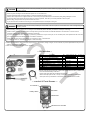
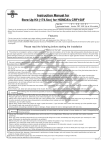
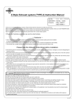
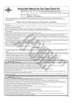
FI Controller Instruction Manual
Item No. 05―04―0003
Fits & Frame No.
CO
Super cub 110 (FI) JA07-1000001∼
・Thank you for purchasing one of our products. Please strictly follow the instructions to install and use the products.
・Before installing the products, please be sure to check the contents of the kit. If you have any questions about the products, please kindly contact your
local our dealer.
◎ Please note: Illustrations and photos may vary from actual hardware.
∼ Features ∼
○This FI unit can control stock ECU.
○This FI unit can adjust inject time based on stock ECU to match the engine specification.
○It is possible to inject fuel more than stock ECU.
○ You can adjust by turn the rotary switch.
Please read the following instructions before installation.
◎ We do not take any responsibility for any accident or damage whatsoever arising from the use of this product not in conformity with the instructions in
this Manual.
◎ We shall be held free and harmless from any and all liabilities or claims for any defects of the parts / the product after installation, and use, and/or any
other products/parts.
◎ SPECIAL PARTS TAKEGAWA Co.,Ltd. does not accept returns and/or repairs on any parts which have been modified and/or installed on a vehicle.
◎ We do not have any information or service data on the combination of our products and other manufacturer’s products.
◎ This products is designed for exclusive use with the above mentioned year of make and models.
◎When ordering repair parts, please quote the Repair Part Item No. (and the Photo No.) If you have any questions, please contact your local TAKEGAWA
dealer.
◎ This product is designed to adjust the injection time by connecting to the genuine ECU injection wire harness.
In the case of technical trouble (like the breakdown) of this product or faulty wiring, the fuel injection may stop.
◎ Rev limiter release function does NOT exist.
◎ Fuel injection adjustment data including in the kit is based on tests of our own motorcycle equipped with our products.
If your motorcycle is different spec from our tested spec or have other manufacturers’ parts, our product may not be able to work properly.However, even
though your motorcycle is equipped with our products, in some cases, you may not get our intended settings because of the individual part differences
and foreign elements such as fuel, temperatures, humidity, altitude or rider’s size / weight.
◎ Before riding, always check and see if the setting is correct for your motorcycle. Please use this product after fully understanding of above instructions.
PY
Precautions to use this kit
◎ DO NOT USE the following parts with this FI controller.
DO NOT USE aftermarket H.I.D. kits. Many of aftermarket H.I.D. kits emit noise of high voltage from the ballast/inverter(a device to convert the voltage) and
adversely affect the digital circuit. It can/will cause failure or malfunction.
DO NOT USE ignition systems in aftermarket such as ignition coil or plug wire, because many of ignition systems in aftermarket increase the radiation noise
due to increase the ignition voltage. It can/will cause malfunction or product failure.
DO NOT USE generating systems in aftermarket, because many of them cannot charge enough electricity and battery voltage lowers. Also, they cannot
control voltage. Those can/will cause malfunctions.
◎ This product is NOT waterproof or drip-proof.
Since this product is not waterproof or drip-proof, it may damage if this controller gets wet with rain or water, or water enters the controller body.
Be careful when washing as well. Stop using the controller immediately when the controller body gets wet.
Also, be careful if you use the transparent switch panel in the kit. When it is humid or the temperature changed suddenly, the controller body may get the
moisture inside and the transparent panel fogs up.
◎ The housing of controller is plastic.
Cover the vehicle to avoid deterioration when parking the vehicle outside for a long time.
If the controller is left in the severe conditions such as hot climates for a long time, the plastic or rubber may deteriorate or deform.
◎HANDLE WITH CARE. NEVER disassemble the controller.
It’s VERY DANGEROUS!! NEVER disassemble or modify this controller.
NOTE: If it is disassembled, we do not accept any maintenance or repair.
◎ DO NOT give an excessive impact.
DO NOT give an excessive impact to this product with riding on off-road or jumping.
By the impact, malfunctions may occur, including the breakage of the inner parts, unrepairable failure due to the disconnection or damage of the controller
housing.
◎ How to clean
If the dirt is stubborn, wipe the dirt with a soft cloth slightly moistened with a mild detergent solution and clean gently and carefully. To prevent adversely
affecting the plastic material or fogging up the panel, DO NOT use a rubbing compound or volatile solvents such as alcohol or paint thinner.
-1-
Sep./30/’
11
CAUTION
The following show the envisioned possibility of injuries to human bodies or property damage as a result of disregarding the
following cautions.
・Please drive safely and follow the local traffic laws.
・Work only when the engine and the exhaust system are cool to avoid burns.
・Prepare appropriate tools and work properly to avoid the breakage of parts or injuries.
・Always use a torque wrench to tighten bolts and nuts securely to the specified torque to avoid these parts getting damaged or loose.
・As some products and frames have sharp edges or protruding portions, work with your hands protected to avoid injuries.
・Before riding, always check such parts as screws for loose.
If you find loose ones, screw them securely up to the specified torque to avoid parts coming off.
CO
The following show the envisioned possibility of human death or serious injuries to human bodies as a result of disregarding the
WARNING following cautions.
・When you notice something abnormal with your motorcycle, stop riding immediately and park your motorcycle in a safe place to avoid an accident.
・Before working, place the motorcycle on level ground to stabilize its position for safety to avoid the motorcycle overturning.
・Please conduct checkups and maintenance correctly referring to the instructions and methods described in the instruction or service manual. (Improper checkups and maintenance could lead to accidents.)
・If you find damaged parts when inspecting or performing maintenance of your motorcycle, do not use these parts, and replace them with new ones.
(The continued use of these damaged parts could lead to accidents.)
・Keep plastic bags for packing the products out of children’s reach, or discard them.
(If children get them on, there will be a danger of their suffocating.)
◎ Please be informed that, mainly because of improvement in performance, design changes, or cost increase, the product specifications and prices are
subject to change without prior notice.
◎ This manual should be retained for future reference.
9
1、2
8
4
3
5
PY
∼ Kit includes ∼
7
6
No.
1
2
3
4
5
6
7
8
9
Part Name
FI Controller Assembly
FI Controller panel (bored switch)
FI Controller panel (transparent switch)
Rubber cap
Sub wire harness 1 COMP.
Sub wire harness 2 COMP.
Ground wire
Velcro set
Insulation lock, 150 mm
Qty
1
1※
1
1
1
1
1
1
2
Repair Part Item No.
In packs of
00-05-0044
1
00-05-0045
00-05-0041
00-05-0042
00-05-0043
00-00-0150
00-00-0135
1
1
1
1
1
10
※The FI Controller panel of Item No. 2 above with a bored switch is factory-installed onto
the FI Controller assembly of Item No.1.
Please order repair parts with the Repair Part Item No.
Without the repair part item No., we may not be able to provide the correct parts.
Some parts are only available as a set. Please order them with the set number.
∼ Product & Parts Names ∼
FI controller
Red LED
Rotary switch
Green LED
Harness for FI controller
-2-
Sep./30/’
11
∼ Installation Procedures ∼
3.Disconnect the genuine injector wire harness(2P coupler).
●Before installation
This product must be installed with the stock PGM-FI system which operates
properly.
If the PGM-FI system is in bad condition, this controller will not operate correctly
CO
or provide the performance, as a result it causes damage of this product or
other related parts.
To install and use this controller, make sure that your stock PGM-FI system
operates properly. Before you start working, stand your vehicle securely on
a flat surface such as a maintenance stand placed on a jack.
1.Remove the center cover, Right side cover, front cover and leg shield
・(referring to the genuine service manual).
Center cover
4.Check the wire color of the disconnected genuine harness(2P coupler).
If the sub wire harness 1COMP. in the kit and the wire colors are
opposite in color, do the following procedure to counterchange the places
of the genuine coupler wires.(Color of wires has to be matched.)
R. side cover
Front cover
Leg shield
Caution: If the wires are opposite in color, you cannot turn on the FI controller, therefore, the engine will not start.
◆ Procedures to counterchange the wires of 2P coupler
a.Remove the retainer(grey plastic part) from the stock coupler with a small slotted driver.
PY
b.Pull out the wires individually from the coupler with a pick while pulling up
the inner hook fixing the terminal of the stock coupler. At this time, you do
not have to remove the retainer on wire side and rubber seal.
2.Attach the supplied ground wire with the battery negative terminal, and
the wire will be routed to the ignition coil.
c.Insert the wires to the coupler to match the colors of the sub wire harness 1 COMP. included in the kit and push the retainer back into the coupler.
Caution:Make sure that the terminal should be pushed in with facing up,
or the terminal will not insert into the coupler. Be careful not to insert upside down.
-3-
Sep./30/’
11
6.Install the removed exteriors in the reverse order of removal.
●The wire connection of FI Controller
.
D
ST
G
38775 - F C1-T 00
MADE IN JAPAN
0123456789ABCDEF
SW. Pos.
POWER
.
E xt t
ec
I nj
e
T im
1.Connect the FI controller and the bullet terminal of sub wire harness referring to the
following diagram.
Do Not connect
CO
ADD FUEL
To the injector
P/G
B / Bl
Sub wire harness 1COMP.
Br
Br
R
Ground wire
B
To the stock wire harness
P/G
B / Bl
Sub wire harness 2COMP.
B…Black G…Green R…Red Br…Brown Bl…Blue P…Pink
Wires of FI controller
Green(Female bullet terminal)
Green(Male bullet terminal)
Brown(Male bullet terminal)
Red(Female bullet terminal)
Brown(Female bullet terminal)
Red(Male bullet terminal)
Connect to
DO NOT connect
Ground wire
Sub wire harness –1COMP. Pink/Green(Female bullet terminal)
Sub wire harness-1COMP. Black/Blue(Male bullet terminal)
Sub wire harness-2COMP. Pink/Green(Male bullet terminal)
Sub wire harness-2COMP. Black/Blue(Female bullet terminal)
Caution: Be careful NOT to pinch the wire harness in FI controller.
7.Referring to the “Recommended settings for the specified models or specs” in this page, adjust the FI controller switch
at the designated setting No. which matches your engine specifications. Then, attach the supplied rubber cap onto the switch panel.
Caution: Attach the rubber cap securely. If the rubber is wrongly fit on the switch, there will be a gap between the rubber cap and the panel of the FI controller. This may cause the rubber cap to fall off or let the dust or water get into the FI controller
through the gap, which may ultimately lead to the
breakdown of the FI controller.
2.Connect the coupler of the sub wire harness 1 COMP. to the injector.
Connect the coupler of the sub wire harness 2 COMP. to the 2P coupler of the genuine wire harness.
PY
●About the rubber cap and panel:
・Remove the rubber cap ONLY when you adjust the rotary switch.
Caution: If you drive your motorcycle without the rubber cap on, the dust or water may get into FI controller,
causing it to break down. When riding, be sure to
cover the top with the rubber cap or the transparent panel in the kit.
3.Route the wire harness of FI controller with the wire harness of the motorcycle and
route inside the Right side cover.
・When the setting is finished, peel off the panel stuck on the Mount the FI controller with the supplied Velcro strap.
switch at the time of shipment from factory, and replace the panel with the transparent one. And this increases the dust- proof and drip-proof quality of the product, leading to the
prevention of the needless troubles.
Caution: When attaching the panel, please paste it right on
the octagonal recessed surface on the FI controller.
If the panel is fit on the edge, not on the recessed
surface or the groove, then the dust or water will
get into the controller through the gap.
Please place panel properly.
4.Make sure if the wiring is properly connected.
5.Turn on the ignition switch.
When turning on the switch, make sure that green LED and red LED of FI controller
will light up and red LED will flash three times.
Caution: We check whether all the products operate properly before shipment.
If the LED does not light up, the wiring might be incorrect. Turn off the Iignition switch immediately and check if the wiring is connected correctly.
-4-
Sep./30/’
11
●How to use the FI controller and about the setting:
●Trouble shooting●
1.The setting of the FI controller can be adjusted by turning the yellow rotary switch.
If you find some failure after installation of FI controller, first, check to see the
section in the following list.
Please turn the switch carefully with a flat extra-fine tip crewdriver
(DO NOT deform the grooves).
CO
Problems
WARNING : NEVER adjust the settings while riding. Otherwise, this may
cause the consequential accidents.
CAUTION : When the controller switch is ON (Green LED is lighting up)
and the setting is changed by turning rotary switch, the new setting will not be valid yet until you turn off the switch
and turn it on again.
Check point
↓
How to fix
LED on FI controller does not When LED does not light up, possible cause
light up even though the is faulty wiring.
↓
ignition switch is on.
Check if the wiring is connected correctly
referring to “the wire connection of FI Controller” diagram.
Check whether the 2P coupler of genuine
wire harness and the sub wire harness
2COMP. are connected with same color.
If the ground wire is connected to the
different point from the instruction manual,
the ground wire may not work properly.
Please connect the ground wire to the point
as instructed.
2.Number or Alphabets show its setting position.
(please refer following chart)
3.Be sure dialed on clicks.
PY
4.When the green LED is on, this indicates that FI controller is powered.
When the FI controller is operating properly, the green LED lights up.
(The ignition switch must be “ON”.)
5.When the ignition switch is turned on, red LED will flash three times by
self-checking program. If the red LED does not light up or does not flash,
turn off the ignition switch, wait for 10 seconds, and turn it on again.
Electric starter works, but the Make sure that the engine starts with a kick
engine does not start.
starter.
↓
If the engine starts by kick starter but the
electric starter does not work, it might be
caused by poor battery condition.
Charge or replace the battery.
●Recommended settings for the specified models or specs
・The following table of the settings are only for the motorcycles equipped with our parts.
・These recommended settings are only the samples. They may vary with conditions such as ambient temperature, altitude, humiduty or rider’s weight.
SW
0
1
2
3
4
5
6
7
8
9
A
B
C
D
E
F
Engine modification level.
Stock displacement + Stock camshaft + Bomber exhaust system.
Stock displacement + Sports camshaft + Stock exhaust system.
Stock displacement + Sports camshaft + Bomber exhaust system.
Stock displacement + Sports camshaft + Bomber exhaust system. (2%
Stock displacement + Sports camshaft + Bomber exhaust system. (4%
Stock displacement + Sports camshaft + Bomber exhaust system. (6%
Stock displacement + Sports camshaft + Bomber exhaust system. (8%
S-Stage + Stock camshaft + Stock exhaust system.
S-Stage + Stock camshaft + Bomber exhaust system.
S-Stage + Sports camshaft + Stock exhaust system.
S-Stage + Sports camshaft + Bomber exhaust system.
S-Stage + Sports camshaft + Bomber exhaust system. (2% richer than
S-Stage + Sports camshaft + Bomber exhaust system. (4% richer than
S-Stage + Sports camshaft + Bomber exhaust system. (6% richer than
S-Stage + Sports camshaft + Bomber exhaust system. (8% richer than
richer
richer
richer
richer
than
than
than
than
#3)
#3)
#3)
#3)
#B)
#B)
#B)
#B)
※ There is no pre set data on #0.
Co.,Ltd.
3-5-16 Nishikiorihigashi Tondabayashi Osaka Japan
TEL : 81-721-25-1357 FAX : 81-721-24-5059
URL : http://www.takegawa.co.jp
-5-
Sep./30/’
11