1
L5006tm and L5009tm Touchscreen Monitors
User Guide
© 2006–2009 Hewlett-Packard
Development Company, L.P.
Microsoft, Windows, and Windows Vista are
either trademarks or registered trademarks
of Microsoft Corporation in the United States
and/or other countries.
Elo TouchSystems, IntelliTouch and
TouchTools are trademarks of Tyco
Electronics Corporation.
The only warranties for HP products and
services are set forth in the express warranty
statements accompanying such products
and services . Nothing herein should be
construed as constituting an additional
warranty. HP shall not be liable for technical
or editorial errors or omissions contained
herein.
This document contains proprietary
information that is protected by copyright. No
part of this document may be photocopied,
reproduced, or translated to another
language without the prior written consent of
Hewlett-Packard Company.
Third Edition (October 2009)
Document Part Number: 419998-003
About This Guide
This guide provides information on setting up the monitor, installing drivers, using the on-screen display
menu, troubleshooting and technical specifications.
WARNING! Text set off in this manner indicates that failure to follow directions could result in bodily
harm or loss of life.
CAUTION: Text set off in this manner indicates that failure to follow directions could result in damage
to equipment or loss of information.
NOTE:
ENWW
Text set off in this manner provides important supplemental information.
iii
iv
About This Guide
ENWW
Table of contents
1 Product Features
HP L5006tm Touchscreen .................................................................................................................... 1
HP Compaq L5009tm Touchscreen ..................................................................................................... 2
2 Safety and Maintenance Guidelines
Important Safety Information ................................................................................................................ 3
Maintenance Guidelines ....................................................................................................................... 4
Cleaning the Monitor ............................................................................................................ 4
Shipping the Monitor ............................................................................................................ 4
3 Setting Up the Monitor
Identifying Rear Connectors ................................................................................................................. 5
Connecting the Cables ......................................................................................................................... 6
Installing the Serial or USB Touch Drivers ........................................................................................... 7
Downloading Drivers from the Web ..................................................................................... 7
Installing Drivers from the CD .............................................................................................. 7
Removing the Monitor Stand ................................................................................................................ 8
Mounting the Monitor to a Desktop ...................................................................................................... 8
Tilting the Monitor ................................................................................................................................. 9
Locating the Rating Labels ................................................................................................................... 9
4 Operating the Monitor
Installing the Monitor Driver ................................................................................................................ 10
The Information File ........................................................................................................... 10
The Image Color Matching File .......................................................................................... 10
Installing the .INF and .ICM Files ....................................................................................................... 11
Installing from the CD ........................................................................................................ 11
Downloading from the Worldwide Web .............................................................................. 11
Adjusting the Monitor .......................................................................................................................... 11
Front Panel Controls .......................................................................................................................... 12
Using the On-Screen Display ............................................................................................................. 13
OSD Menu Table ............................................................................................................... 13
Identifying Monitor Conditions ............................................................................................................ 14
Power Management System .............................................................................................................. 14
ENWW
v
OSD and Power Lock/Unlock ............................................................................................................. 15
Appendix A Troubleshooting
Solving Common Problems ................................................................................................................ 16
Touchscreen Tips ............................................................................................................................... 17
Online Technical Support ................................................................................................................... 19
Preparing to Call Technical Support ................................................................................................... 19
Appendix B Technical Specifications
HP L5006tm Touchscreen .................................................................................................................. 20
HP Compaq L5009tm Touchscreen ................................................................................................... 21
IntelliTouch Surface Acoustic Wave Technology ............................................................................... 23
Acoustic Pulse Recognition Technology ............................................................................................ 24
Recognizing Preset Display Resolutions ............................................................................................ 25
HP L5006tm and L5009tm ................................................................................................. 25
Entering User Modes .......................................................................................................................... 25
Energy Saver Feature ........................................................................................................................ 26
Appendix C Agency Regulatory Notices
Federal Communications Commission Notice ................................................................................... 27
Modifications ...................................................................................................................... 27
Cables ................................................................................................................................ 27
Declaration of Conformity for Products Marked with the FCC Logo (United States Only) ................. 27
Canadian Notice ................................................................................................................................. 28
Avis Canadien .................................................................................................................................... 28
European Union Regulatory Notice .................................................................................................... 28
German Ergonomics Notice ............................................................................................................... 29
Japanese Notice ................................................................................................................................. 29
Korean Notice ..................................................................................................................................... 29
Power Cord Set Requirements ........................................................................................................... 29
Japanese Power Cord Requirements ................................................................................ 29
Product Environmental Notices .......................................................................................................... 30
Materials Disposal ............................................................................................................. 30
Disposal of Waste Equipment by Users in Private Household in the European
Union ................................................................................................................................. 30
HP Recycling Program ...................................................................................................... 30
Chemical Substances ........................................................................................................ 30
Restriction of Hazardous Substances (RoHS) ................................................................... 30
Turkey EEE Regulation ..................................................................................................... 31
Appendix D Native Resolution
vi
ENWW
1
Product Features
The LCD (liquid crystal display) monitors have an active matrix, thin-film transistor (TFT) panel. The
monitors feature:
HP L5006tm Touchscreen
ENWW
●
Maximum resolution of XGA 1024 x 768. Compatible with VGA, SVGA and XGA (non-interlace)
color video cards
●
Integrated IntelliTouch touchscreen technology from the Elo TouchSystems business of Tyco
Electronics Corporation
●
Sealed touchscreen responds to touch with finger, gloved hand, or soft stylus
●
Tilt capability
●
USB and Serial touch cables provided
●
Power and video cables provided
●
Video input supports analog signal inputs
●
Plug and play capability if supported by the system
●
On-Screen Display (OSD) adjustments in several languages for easy setup and screen
optimization
●
Software and documentation CD that includes the Elo TouchSystems IntelliTouch software, HP
monitor driver software and product documentation
●
Detachable stand for wall mounting application
●
Compliant with Swedish MPR II 1990 regulated specifications
HP L5006tm Touchscreen
1
HP Compaq L5009tm Touchscreen
2
●
Maximum resolution of XGA 1024 x 768. Compatible with VGA, SVGA and XGA (non-interlace)
color video cards
●
Integrated Acoustic Pulse Recognition (APR) technology from the Elo TouchSystems business of
Tyco Electronics Corporation
●
Sealed touchscreen responds to touch with finger, finger nail, gloved hand, pen or stylus activation
●
Tilt capability
●
Power, video and APR USB cables provided
●
Video input supports analog signal inputs
●
Plug and play capability if supported by the system
●
On-Screen Display (OSD) adjustments in several languages for easy setup and screen
optimization
●
Software and documentation CD that includes the Elo TouchSystems APR USB touch driver, HP
monitor driver software and product documentation
●
Detachable stand for wall mounting application
●
Compliant with Swedish MPR II 1990 regulated specifications
●
TCO Displays Requirement
Chapter 1 Product Features
ENWW
2
Safety and Maintenance Guidelines
Important Safety Information
A power cord is included with the monitor. If another cord is used, use only a power source and
connection appropriate for this monitor. For information on the correct power cord set to use with the
monitor, refer to the Power Cord Set Requirements on page 29 in Appendix C.
WARNING! To reduce the risk of electric shock or damage to the equipment:
• Do not disable the power cord grounding feature. The grounding plug is an important safety feature.
• Plug the power cord in a grounded (earthed) outlet that is easily accessible at all times.
• Disconnect power from the product by unplugging the power cord from the electrical outlet.
For your safety, do not place anything on power cords or cables. Arrange them so that no one may
accidentally step on or trip over them. Do not pull on a cord or cable. When unplugging from the electrical
outlet, grasp the cord by the plug.
To reduce the risk of serious injury, read the Safety and Comfort Guide. It describes proper workstation,
setup, posture, and health and work habits for computer users, and provides important electrical and
mechanical safety information. This guide is located on the Web at http://www.hp.com/ergo and/or on
the documentation CD, if one is included with the monitor.
CAUTION: For the protection of the monitor, as well as the computer, connect all power cords for the
computer and its peripheral devices (such as a monitor, printer, scanner) to some form of surge
protection device such as a power strip or Uninterruptible Power Supply (UPS). Not all power strips
provide surge protection; the power strips must be specifically labeled as having this ability. Use a power
strip whose manufacturer offers a Damage Replacement Policy so you can replace the equipment, if
surge protection fails.
Use the appropriate and correctly sized furniture designed to properly support your HP LCD monitor.
WARNING! LCD monitors that are inappropriately situated on dressers, bookcases, shelves, desks,
speakers, chests, or carts may fall over and cause personal injury.
Care should be taken to route all cords and cables connected to the LCD monitor so that they can not
be pulled, grabbed, or tripped over.
ENWW
Important Safety Information
3
Maintenance Guidelines
To enhance the performance and extend the life of the monitor:
●
Do not open the monitor cabinet or attempt to service this product yourself. Adjust only those
controls that are covered in the operating instructions. If the monitor is not operating properly or
has been dropped or damaged, contact an authorized HP dealer, reseller, or service provider.
●
Use only a power source and connection appropriate for this monitor, as indicated on the label/
back plate of the monitor.
●
Be sure the total ampere rating of the products connected to the outlet does not exceed the current
rating of the electrical outlet, and the total ampere rating of the products connected to the cord does
not exceed the rating of the cord. Look on the power label to determine the ampere rating (AMPS
or A) for each device.
●
Install the monitor near an outlet that you can easily reach. Disconnect the monitor by grasping the
plug firmly and pulling it from the outlet. Never disconnect the monitor by pulling the cord.
●
Turn the monitor off when not in use. You can substantially increase the life expectancy of the
monitor by using a screen saver program and turning off the monitor when not in use.
●
Slots and openings in the cabinet are provided for ventilation. These openings must not be blocked
or covered. Never push objects of any kind into cabinet slots or other openings.
●
Do not drop the monitor or place it on an unstable surface.
●
Do not allow anything to rest on the power cord. Do not walk on the cord.
●
Keep the monitor in a well-ventilated area, away from excessive light, heat or moisture.
●
When removing the monitor base, you must lay the monitor face down on a soft area to prevent it
from getting scratched, defaced, or broken.
Cleaning the Monitor
1.
Turn off the monitor and the computer.
2.
Unplug the monitor from the wall outlet.
3.
To clean the display unit cabinet, use a cloth lightly dampened with a mild detergent.
4.
Clean the touchscreen with window or glass cleaner. Put the cleaner on the cloth and wipe the
touchscreen. Never apply the cleaner directly to the touchscreen.
CAUTION: Do not use alcohol (methyl, ethyl or isopropyl) or any strong dissolvent. Do not use thinner
or benzene, abrasive cleaners or compressed air.
Avoid getting liquids inside the touchmonitor. If liquid does get inside, have a qualified service technician
check it before you power it on again.
Do not wipe the screen with a cloth or sponge that could scratch the surface.
Shipping the Monitor
Keep the original packing box in a storage area. You may need it later if you move or ship the monitor.
4
Chapter 2 Safety and Maintenance Guidelines
ENWW
3
Setting Up the Monitor
To set up the monitor, ensure that the power is turned off to the monitor, computer system, and other
attached devices, then follow the instructions below.
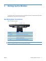
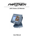
Identifying Rear Connectors
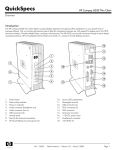
Figure 3-1 Rear Connectors
Connector
Function
1
AC Power
Connects the AC power cord to the monitor.
2
USB
Connects the touchscreen USB cable to the monitor.
3
Serial
Connects the touchscreen serial cable to the monitor (not
available on L5009tm model).
4
VGA
Connects the VGA video cable to the monitor.
NOTE: A +12VDC input jack is available on the connector panel of the L5009tm monitor. This jack
accepts an external DC power brick (not included with the monitor).
ENWW
Identifying Rear Connectors
5
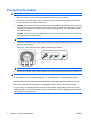
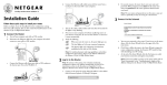
Connecting the Cables
NOTE:
For the L5009tm model, it is best to install the APR driver before connecting the hardware.
1.
Place the monitor in a convenient, well-ventilated location near the computer.
2.
Connect one end of the power cable (1) to the AC power connector on the back of the monitor,
and the other end to an electrical wall outlet.
3.
L5006tm: Connect one end of the touchscreen serial cable (RS232) or USB cable (2), but not both,
to the rear connector of the computer, and the other end to the connector on the monitor. Tighten
the two thumb screws on the serial cable to ensure proper grounding. The USB cable does not
have thumb screws.
L5009tm: Connect one end of the USB cable to the rear connector of the computer, and the other
end to the connector on the monitor.
NOTE: The L5009tm model does not include a serial connector.
4.
Connect one end of the video cable (3) to the rear side of the computer and the other to the VGA
connector on the monitor.
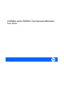
Figure 3-2 Connecting the Power, USB or Serial and VGA Cables
NOTE: Connect either the USB or serial cable to the L5006tm monitor, but not both.
5.
Turn on the computer, then press the power button on the side panel to turn the monitor power on.
WARNING! To reduce the risk of electric shock or damage to the equipment:
Do not disable the power cord grounding plug. The grounding plug is an important safety feature.
Plug the power cord into a grounded (earthed) electrical outlet that is easily accessible at all times.
Disconnect power from the equipment by unplugging the power cord from the electrical outlet.
For your safety, do not place anything on power cords or cables. Arrange them so that no one may
accidentally step on or trip over them. Do not pull on a cord or cable. When unplugging from the electrical
outlet, grasp the cord by the plug.
6
Chapter 3 Setting Up the Monitor
ENWW
Installing the Serial or USB Touch Drivers
The Touch driver software can be downloaded from the Web or from the HP software and documentation
CD included with the monitor.
Downloading Drivers from the Web
1.
Insert the HP software and documentation CD in the computer’s CD-ROM drive. The CD will open
to a menu screen.
2.
From the menu screen, select Elo TouchSystems TouchTools.
3.
Click Install Driver for This Computer.
4.
Click Yes to download the latest drivers from the Elo Website.
5.
Select your operating system version for touch drivers from the Elo Driver and File Downloads
page.
NOTE: Depending on whether you connected the USB cable or serial cable, you should install
only the USB driver or serial driver.
6.
Refer to the online help file with the software for instructions on configuring and adjusting the
touchscreen.
Installing Drivers from the CD
1.
Insert the HP software and documentation CD in the computer’s CD-ROM drive. The CD will open
to a menu screen.
2.
From the menu screen, select Elo TouchSystems TouchTools.
3.
Click Browse CD.
4.
Browse to the latest version of the EloWinXP Universal directory containing the driver installation
package files.
5.
Double-click on EloSetup.exe to run the install application for:
●
Serial or USB touchscreen driver (L5006tm)
NOTE: Depending on whether you connected the USB or serial cable, you should install
only the USB driver or serial driver.
●
APR USB touchscreen driver (L5009tm)
NOTE: It is best to install the APR driver before connecting the USB cable to the L5009tm
monitor and to the computer. Do not turn off the computer before connecting the USB cable.
There is no APR serial (RS232) driver version available for the L5009tm monitor.
6.
ENWW
Click Next and follow the on screen instructions to complete the touchscreen setup process.
Installing the Serial or USB Touch Drivers
7
Removing the Monitor Stand
If you are mounting the panel to a wall or other mounting fixture, you must remove the monitor stand
from the panel. The monitor has four mounting holes on the back side of the panel that adheres to the
VESA mounting standard.
CAUTION: This monitor supports the VESA industry standard 75mm mounting holes. To attach a third
party mounting solution to the monitor, four 4mm, 0.7 pitch, and 10mm long screws are required (not
provided with the monitor). Longer screws should not be used because they may damage the monitor.
It is important to verify that the manufacturer’s mounting solution is compliant with the VESA standard
and is rated to support the weight of the monitor display panel. For best performance, it is important to
use the power and video cable provided with the monitor.
To remove the stand and mount the panel:
1.
Turn off the monitor and computer.
2.
Disconnect the power, USB or serial and video cables from the monitor and the computer.
3.
Lay the monitor face down on a flat surface covered with soft protective cloth.
4.
Remove the four screws that secure the stand to the back of the monitor.
5.
Follow the instructions from the manufacturer to install the panel to the manufacturer’s mounting
fixture.
6.
Reconnect the power, USB or serial and video cables to the monitor and the computer.
7.
Turn on the computer, then turn on the monitor.
Mounting the Monitor to a Desktop
The monitor can be screwed down on a desktop or a tabletop to provide security. Four mounting holes
are available on the base of the stand for mounting the monitor.
8
1.
Turn off the monitor and computer.
2.
If necessary, disconnect the power, USB or serial and video cables from the monitor and the
computer.
3.
Position the monitor on the desk or tabletop.
4.
Lift the bezel cover from the base of the stand.
5.
Install the screws into the holes provided and replace the bezel cover.
6.
Reconnect the monitor cables and turn it on.
Chapter 3 Setting Up the Monitor
ENWW
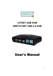
Tilting the Monitor
For viewing clarity, tilt the monitor forward (up to -5 degrees) or backward (up to 90 degrees).
Figure 3-3 Tilting the Monitor
CAUTION: In order to protect the monitor, be sure to hold the base when adjusting the LCD, and take
care not to touch the screen.
Locating the Rating Labels
The rating labels on the monitor provide the spare part number, product number, and serial number.
You may need these numbers when contacting HP about the monitor model. The rating labels are
located on the rear panel of the monitor display head.
ENWW
Tilting the Monitor
9
4
Operating the Monitor
Installing the Monitor Driver
The CD that comes with the monitor contains monitor driver files you can install on your computer:
●
an .INF (Information) file
●
an .ICM (Image Color Matching) file
PDF Complete is supplied on this CD and can be installed from the menu.
NOTE: If the monitor does not include a CD, the .INF and .ICM files can be downloaded from the HP
monitors support Web site. See Downloading from the Worldwide Web on page 11 in this chapter.
The Information File
The .INF file defines monitor resources used by Microsoft Windows operating systems to ensure monitor
compatibility with the computer’s graphics adapter.
This monitor is Microsoft Windows Plug and Play compatible and the monitor will work correctly without
installing the .INF file. Monitor Plug and Play compatibility requires that the computer’s graphic card is
VESA DDC2 compliant and that the monitor connects directly to the graphics card. Plug and Play does
not work through separate BNC type connectors or through distribution buffers/boxes.
The Image Color Matching File
The .ICM files are data files that are used in conjunction with graphics programs to provide consistent
color matching from monitor screen to printer, or from scanner to monitor screen. The .ICM file contains
a monitor color system profile. This file is activated from within graphics programs that support this
feature.
NOTE: The ICM color profile is written in accordance with the International Color Consortium (ICC)
Profile Format specification.
10
Chapter 4 Operating the Monitor
ENWW
Installing the .INF and .ICM Files
After you determine that you need to update, you can install the .INF and .ICM files from the CD or
download them.
Installing from the CD
To install the .INF and .ICM files on the computer from the CD:
1.
Insert the CD in the computer CD-ROM drive. The CD menu is displayed.
2.
View the Monitor Driver Software Readme file.
3.
Select Install Monitor Driver Software.
4.
Follow the on-screen instructions.
5.
Ensure that the proper resolution and refresh rates appear in the Windows Display control panel.
NOTE: You may need to install the digitally signed monitor .INF and .ICM files manually from the CD
in the event of an installation error. Refer to the Monitor Driver Software Readme file on the CD.
Downloading from the Worldwide Web
To download the latest version of .INF and .ICM files from the HP monitors support Web site:
1.
Refer to http://www.hp.com/support and select the country region.
2.
Follow the links for the monitor to the support page and download page.
3.
Ensure the system meets the requirements.
4.
Download the software by following the instructions.
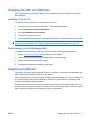
Adjusting the Monitor
The monitor will unlikely require adjustment. However, variations in video output and application may
require adjustments to optimize the quality of the display.
For best performance, the monitor should be operating in native resolution, that is 1024 x 768 at 60 -75
Hz. Use the Display control panel in Windows to choose 1024 x 768 resolution. Operating in other
resolutions will degrade video performance.
All adjustments you make to the controls are automatically memorized. This feature saves you from
having to reset your choices every time you unplug or power your monitor off and on. If there is a power
failure, the monitor settings will not default to the factory specifications.
ENWW
Installing the .INF and .ICM Files
11
Front Panel Controls
Table 4-1 Monitor Front Panel Controls
Control
Function
1
Power
Turns the monitor on or off.
2
Select
Selects the adjustment items from the OSD menus.
3
Enter the brightness adjustment.
Decrease value of the adjustment item.
Select item counter-clockwise.
4
Enters contrast adjustment.
Increase value of the adjustment item.
Select item.
5
12
Menu/Exit
Displays or exits the OSD menus.
Chapter 4 Operating the Monitor
ENWW
Using the On-Screen Display
Use the On-Screen Display (OSD) to display and select OSD menu functions. To access the OSD, do
the following:
1.
Press the Menu button on the side panel to activate the OSD menu.
2.
Use the up arrow or down arrow controls to move clockwise or counterclockwise through the menu.
Press the Enter key on the keyboard, the parameter will be highlighted when selected.
3.
To quit the OSD screen at any time during the operation, press the Menu button. If the OSD remains
untouched for a short period of time, the OSD automatically disappears.
NOTE:
The OSD screen will disappear if no input activities are detected for 45 seconds.
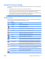
OSD Menu Table
The following table lists the On-Screen Display (OSD) menu selections and their functional descriptions.
Settings will be saved automatically after adjustments are made.
Table 4-2 OSD Menu
Icon
ENWW
OSD Control
Description
Brightness
Increases or decreases brightness.
Contrast
Increases or decreases contrast.
H-Position
Adjusts the position of the screen image left and right.
V-Position
Adjusts the position of the screen image up and down.
Phase
Adjusts the focus of the display. This adjustment allows you to remove any horizontal
noise and clear or sharpen the image of characters.
Clock
Minimizes any vertical bars or strips visible on the screen background. Adjusting the
Clock will also change the horizontal screen image.
Sharpness
Adjusts the screen image to look sharper or soft.
OSD H-Position
Moves the OSD position horizontally on the screen. When the up arrow button is
pressed, the OSD menu will move to the right side of the screen. Likewise, when the
down arrow button is pressed, the OSD control menu will move to the left side.
OSD V-Position
Moves the OSD position vertically on the screen. When the up arrow button is
pressed, the OSD menu will move to the top side of the screen. Likewise, when the
down arrow button is pressed, the OSD control menu will move to the lower side.
OSD Time
Adjusts the amount of time the OSD menu is displayed.
Color Balance
Press the up arrow button or the down arrow button to select 9300, 6500, 5500, 7500
or USER. Only when selecting USER can you make adjustments to the R/G/B (red/
green/blue) content. Press Enter to restore the factory default setting.
Auto-Adjustment
Press Auto to enable this function. The Auto-Adjustment will automatically adjust VPosition, H-Position, Clock and Clock-Phase.
Recall Defaults
Returns the monitor to its default settings.
Using the On-Screen Display
13
Table 4-2 OSD Menu (continued)
Icon
OSD Control
Description
OSD Language
Selects the language in which the OSD menu is displayed.
Information Description
Indicates the current resolution, H-Frequency and V-Frequency.
NOTE: When adjusting the Clock and Clock Phase values, if the monitor images become distorted,
continue adjusting the values until the distortion disappears. To restore the factory settings, select the
Recall Defaults menu in the on-screen display.
Identifying Monitor Conditions
Special messages will appear on the monitor screen when identifying the following monitor conditions:
●
Out of Range—Indicates the monitor does not support the input signal because the resolution and/
or refresh rate are set higher than the monitor supports.
●
No Input Signal—Indicates the monitor is not receiving a video signal from the PC on the monitor
video input connector. Check to determine if the PC or input signal source is off or in the power
saving mode.
●
Check Video Cable—Indicates the video cable is not properly connected to the computer.
Power Management System
The monitor is equipped with the power management function which automatically reduces the power
consumption when not in use.
Mode
Power Consumption
On
<30 W
Sleep
<4 W
Off
<2 W
It is recommended that you switch the monitor off when it is not in use for a long period of time.
NOTE: The monitor automatically goes through the power management system steps when it is idle.
To release the monitor from the power management system, press any key on the keyboard or move
the mouse or touch the touchscreen. In order for the touchscreen to bring the monitor from the power
management system, the touchscreen function must be fully operational.
Monitor models using the APR driver do not support standby or sleep mode.
14
Chapter 4 Operating the Monitor
ENWW
OSD and Power Lock/Unlock
The OSD feature can be locked and unlocked. The monitor is shipped with the OSD menu and power
button in the unlocked position.
To lock the OSD menu:
1.
Press the Menu button and up arrow button simultaneously until a window displays "OSD Unlock."
Continue to hold the buttons down and the window toggles to "OSD Lock."
2.
To unlock the OSD, repeat the above step until "OSD Unlock" is displayed.
To lock the power button:
ENWW
1.
Press the Menu button and down arrow button simultaneously until a window displays "Power
Unlock." Continue to hold the buttons down until "Power Lock" displays.
2.
To unlock the power button, repeat the above step until "Power Unlock" is displayed.
OSD and Power Lock/Unlock
15
A
Troubleshooting
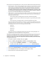
Solving Common Problems
The following table lists possible problems, the possible cause of each problem, and the recommended
solutions.
Problem
Possible Cause
Solution
Screen is blank.
Power cord is disconnected.
Connect the power cord.
Power button on front panel of the
monitor is turned off.
Press the front panel power button.
Video cable is improperly
connected.
Connect the video cable properly. Refer to
Chapter 3, Setting Up the Monitor on page 5 for
more information.
Screen blanking utility is active.
Press any key on the keyboard or move the
mouse to inactivate the screen blanking utility.
The monitor does not respond after
you turn on the system.
Check power.
Check that the monitor’s power switch is on. Turn
off power and check the monitor’s power cord and
signal cable for proper connection.
Image appears blurred, indistinct, or
too dark.
Brightness and contrast are too low.
Press the Menu button to display the OSD. Use
the up arrow button or down arrow button to adjust
the brightness and contrast scales as needed.
Screen flashes when initialized.
Turn the monitor off then turn it on again.
Check Video Cable is displayed on Monitor video cable is disconnected.
screen.
Connect the VGA cable to the VGA connector on
the computer. Be sure that the computer power is
off while connecting the video cable.
Out of Range is displayed on
screen.
16
Appendix A Troubleshooting
Video resolution and/or refresh rate Restart your computer and enter Safe Mode.
are set higher than what the monitor Change your settings to a supported setting
supports.
(see Recognizing Preset Display Resolutions
on page 25 in Appendix B). Restart your
computer so that the new settings take effect.
ENWW
Touchscreen Tips
If you experience operational issues with the touchscreen system either during or after installation, use
the tips below to help you determine the source of the problem.
●
If “No Elo touchmonitor found” is displayed on the screen, install the latest drivers. Touchmonitors
with the dual serial/USB interface require the latest drivers. If you are replacing an existing
installation and see this problem, you should update your touchscreen driver with one from the Elo
Web site Driver and File Downloads page.
●
Be sure to calibrate the L5006tm touchscreen monitor. Touch response must be aligned to the
video image (this is sometimes called calibration). Normally this need only be done when the touch
drivers are initially installed.
NOTE: The L5009tm LCD with APR technology has a fixed coordinate system that never
changes over time, position or environmental changes. With APR, calibration is eliminated.
To calibrate the L5006tm touchscreen:
1.
Click the Windows Start button.
2.
Select Settings > Control Panel (on later operating systems the Settings step is omitted).
3.
Open the Elo application by double-clicking the Elo icon.
On Windows XP it may be necessary to click the Show Classic View button on the left side of the
screen to see the Elo icon.
4.
Click the Alignment/Calibration button.
The Alignment/Calibration button is always on the General tab of the Elo Control Panel tab set. It
may be titled Calibrate, Align or it may just be an icon (fingers and cross marks on a display).
5.
Touch the target that is displayed in the upper left corner. The target will reappear in the lower right
corner.
6.
Touch the lower right target. The target will reappear in the upper right corner.
7.
Touch the upper right target. The next screen is an alignment check.
8.
On the alignment check screen, touch various places on the screen and see that the cursor jumps
to the point of touch.
A progress bar displays the relative time remaining before the routine will time out; if time-out is
reached, the routine is aborted and the new alignment points are not retained.
If response is correct, touch the Accept button - it may be a Yes button or a green check.
Clicking the No or redo arrow icon will display the targets again to rerun the alignment routine.
Remember, you must click the Accept button to store the new alignment points.
ENWW
Touchscreen Tips
17
If the touchscreen is not responding to touch, check your serial or USB connection by doing the following:
●
Serial Connection - Run the comdump diagnostic utility to determine if the touchscreen, the serial
touch controller, the computer's serial COM port and the associated cabling are connected and
functioning properly. Download the latest version of comdump.exe (7K) from the Elo Web site
Driver and Files Download page. You should save the file where it can be accessed easily - either
to a floppy or to the root of your hard drive. Comdump is a DOS application, so if you are running
one of the Windows operating systems you must either boot to a DOS boot diskette or disable the
driver so you can access the COM port from a command prompt.
●
USB Connection - If the Human Interface Device (HID) is not listed in Device Manager after a USB
touchmonitor is connected, check to determine if a file named mouhid.sys is in the \windows (or
winnt) \system32\drivers folder.
◦
The file will be missing if a USB mouse has never been connected to the system.
◦
If the file is not there, connect a USB mouse to the system or copy mouhid.sys from another
system.
◦
Once mouhid.sys is in the proper location, remove and reinstall the touch drivers.
If you have determined that the HID files are missing or corrupted ("Error installing mouse" when
installing the HID drivers, and also a yellow "!" in Device Manager under Mouse), check that all of
the following files are present in the \\winnt\system32\drivers folder:
◦
Hidusb.sys
◦
Hidclass.sys
◦
Hidparse.sys
◦
Mouhid.sys
If all the files are there, try replacing them with the same files from a known good system. It is
suggested that you save the original files in a backup directory.
The touch can not be held longer than 10 seconds. IntelliTouch controllers have a built-in two minute
untouch time-out. By default, the 4.20 Universal driver generates an untouch after 10 seconds of
constant touch. The untouch time-out can be changed by modifying a registry key. This time-out will
override any registry time-out value if the registry value exceeds 120 seconds (120000 milliseconds).
To change the time-out time:
1.
Run regedit or regedt32 (click Start > Run, enter regedit).
2.
Drill down to HKEY_LOCAL_MACHINE > SYSTEM > CurrentControlSet > Enum.
a.
For serial controllers: SERENUM > ELOSERIAL > ******* > Device Parameters.
b.
For USB controllers: HID > VID_04e7 > ******** > ***************** > Device Parameters.
NOTE:
18
The "******" entries are id numbers used by the Windows operating system.
3.
Double-click the UntouchTimeOut key. The Edit DWORD Value dialog box opens.
4.
Click the Decimal radio button. Value displays in decimal (default: 10000).
5.
Enter the delay time in milliseconds, 60000 is 60 seconds.
Appendix A Troubleshooting
ENWW
6.
Exit regedit when done.
7.
Shut Down and restart the machine. A restart is required before the setting will take effect.
A cursor is not visible. To make the cursor visible, first, open Control Panel > Elo Touchscreen >
Mode tab. Check if the Hide arrow mouse pointer box is checked; if yes, un-check it and click OK. If a
mouse is not installed on the computer, Shut Down the computer, install a mouse, then restart the
computer. The cursor should now be visible. You may then Shut Down and remove the mouse, or leave
it connected, as desired.
If connecting multiple monitor systems, all monitors must be configured to have independent resolution
control (as in two monitors, each at 1024 x 786 resolution), rather than a single, large desktop (as in
2048 x 768). Multiple individual video cards are automatically set up as individual monitors. Some
multiport video cards can be configured either way; in this case, the video driver must be set up properly.
Once the multiport video has been properly configured, the Elo Universal driver should be removed and
reinstalled. Some multiport video cards can only be configured as a single large desktop, and they will
not work with Elo's multiple monitor driver setup.
Online Technical Support
For the online access to technical support information, self-solve tools, online assistance, community
forums of IT experts, broad mutlivendor knowledge base, monitoring and diagnostic tools, go to
http://www.hp.com/support
Preparing to Call Technical Support
If you cannot solve a problem using the troubleshooting tips in this section, you may need to call technical
support. Have the following information available when you call:
ENWW
●
The monitor
●
Monitor model number
●
Serial number for the monitor
●
Purchase date on invoice
●
Conditions under which the problem occurred
●
Error messages received
●
Hardware configuration
●
Hardware and software you are using
Online Technical Support
19
B
Technical Specifications
NOTE: All performance specifications are provided by the component manufacturers. Performance
specifications represent the highest specification of all HP's component manufacturers' typical level
specifications for performance and actual performance may vary either higher or lower.
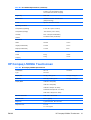
HP L5006tm Touchscreen
Table B-1 HP L5006tm Specifications
LCD Display
38.1 cm
15 inches
Type
TFT LCD
Display Size
304 (H) x 228 (V) mm
12.0 (H) x 9.0 (V) in
Pixel Pitch
0.297 (H) x 0.297 (V) mm
0.01 (H) x 0.01 (V) in
Display Mode
VGA 640 x 350 (70Hz)
VGA 720 x 400 (70Hz)
VGA 640 x 480 (60 / 72/ 75Hz)
SVGA 800 x 600 (56 / 60 / 72 / 75Hz)
XGA 1024 x 768 (60 / 70 / 75Hz)
Maximum Resolution
XGA 1024 x 768 at 75Hz
Contrast Ratio
400 : 1 (typical)
Brightness
Typical 230 Cd/m2; Min 184 Cd/m2
Response Time
Tr: 5 ms
Tf: 12 ms Typical
Display Color
16.2M
Viewing Angle
Vertical -60° ~ +40°
Horizontal -60° ~ +60°
Input Signal
20
Video
R.G.B. Analog 0.7Vp-p, 75 Ohms
Sync
TTL Positive or Negative
Signal Connector
Mini D-Sub 15 pin
Side Control
Menu, up arrow, down arrow, Select,
Power
Appendix B Technical Specifications
ENWW
Table B-1 HP L5006tm Specifications (continued)
OSD
Contrast, Brightness, H-Position, VPosition, Color Temperature, Phase,
Clock, OSD Time, Recall, Language
Plug & Play
DDC1/2B
Touch Panel
IntelliTouch Surface Acoustic Wave
(SAW) technology
Power
Input AC 100-240V, 50-60Hz
Operating Conditions
Temperature (Operating)
0° C to 40° C (32° F to 104° F)
Temperature (Storage)
-20°C to 60°C (-4°F to 140°F)
Humidity
20% ~ 80% (No Condensation)
Altitude
To 3657.6 meters (12,000 feet)
Dimensions
Width
350 mm
13.8 in
Height (includes base)
310 mm
12.2 in
Depth (includes base)
175 mm
6.9 in
Actual
4.8 kg
10.6 lb
Shipping
7.0 kg
15.4 lb
Weight
HP Compaq L5009tm Touchscreen
Table B-2 HP Compaq L5009tm Specifications
LCD Display
38.1 cm
15 inches
Type
TFT LCD
Display Size
304 (H) x 228 (V) mm
12.0 (H) x 9.0 (V) in
Pixel Pitch
0.297 (H) x 0.297 (V) mm
0.01 (H) x 0.01 (V) in
Display Mode
VGA 640 x 350 (70Hz)
VGA 720 x 400 (70Hz)
VGA 640 x 480 (60 / 72/ 75Hz)
SVGA 800 x 600 (56 / 60 / 72 / 75Hz)
XGA 1024 x 768 (60 / 70 / 75Hz)
Maximum Resolution
XGA 1024 x 768 at 75Hz
Contrast Ratio
450 : 1 (typical)
Brightness
Typical 230 Cd/m2; Min 184 Cd/m2
Response Time
Tr: 5 ms
Tf: 12 ms Typical
ENWW
HP Compaq L5009tm Touchscreen
21
Table B-2 HP Compaq L5009tm Specifications (continued)
Display Color
16.2M
Viewing Angle
Vertical -60° ~ +40°
Horizontal -60° ~ +60°
Input Signal
Video
R.G.B. Analog 0.7Vp-p, 75 Ohms
Sync
TTL Positive or Negative
Signal Connector
Mini D-Sub 15 pin
Side Control
Menu, up arrow, down arrow, Select,
Power
OSD
Contrast, Brightness, H-Position, VPosition, Color Temperature, Phase,
Clock, OSD Time, Recall, Language
Plug & Play
DDC1/2B
Touch Panel
Acoustic Pulse Recognition (APR)
Technology
Power
Input AC 100-240V, 50-60Hz
Operating Conditions
Temperature (Operating)
0° C to 40° C (32° F to 104° F)
Temperature (Storage)
-20°C to 60°C (-4°F to 140°F)
Humidity
20% ~ 80% (No Condensation)
Altitude
To 3657.6 meters (12,000 feet)
Dimensions
Width
350 mm
13.8 in
Height (includes base)
310 mm
12.2 in
Depth (includes base)
175 mm
6.9 in
Actual
4.8 kg
10.6 lb
Shipping
7.0 kg
15.4 lb
Weight
22
Appendix B Technical Specifications
ENWW
IntelliTouch Surface Acoustic Wave Technology
Table B-3 IntelliTouch Specifications
Input Method
Finger or gloved hand (cloth, leather or rubber) activation.
Mechanical Positional Accuracy
Standard deviation of error is less than 2.03 mm (0.080 in).
Equates to less than ±1%.
Touchpoint Density
More than 15,500 touchpoints/cm2 (100,000 touchpoints/in2).
Touch Activation Force
Typically less than 85 grams (3 ounces).
Surface Durability
Surface durability is that of glass, Mohs’ hardness rating of 7.
Expected Life Performance
No known wear-out mechanism, as there are no layers,
coatings, or moving parts. IntelliTouch technology has been
operationally tested to more than 50 million touches in one
location without failure, using a stylus similar to a finger
Sealing
Unit is sealed to protect against splashed liquids, dirt, and dust.
Optical Light Transmission (per ASTM D1003)
up to 92%
Visual Resolution
All measurements made using USAF 1951 Resolution Chart,
under 30X magnification, with test unit located approximately
38 mm (1.5 in) from surface of resolution chart
Clear surface: Excellent, with no noticeable degradation.
Antiglare surface: 6:1 minimum.
Gloss (per ASTM D2457 using a 60- degree gloss meter)
Antiglare surface: curved or flat: 95 ± 15 gloss units or 65 ± 15
gloss units; Clear surface: N/A
Environmental Chemical Resistance
The active area of the touchscreen is resistant to all chemicals
that do not affect glass, such as:
Electrostatic Protection (per EN 61 000-4-2, 1995)
ENWW
●
Acetone
●
Toluene
●
Methyl ethyl ketone
●
Isopropyl alcohol
●
Methyl alcohol
●
Ethyl acetate
●
Ammonia-based glass cleaners
●
Gasoline
●
Kerosene
●
Vinegar
Meets Level 4 (15 kV air/8 kV contact discharges).
IntelliTouch Surface Acoustic Wave Technology
23
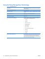
Acoustic Pulse Recognition Technology
Table B-4 APR Specifications
Input Method
Finger, finger nail, solid stylus or gloved hand (cloth, leather or
rubber) activation
Mechanical Positional Accuracy
1% maximum error
Resolution Accuracy
Touchpoint density is based on controllers resolution of 4096
x 4096
Touch Activation Force
Typically 2 to 3 ounces (55 to 85 grams)
Controller
Board: USB 1.1
Optical Light Transmission
90% +/- 5%
Environmental Chemical Resistance
The touch activation area of the touchscreen is resistant to
chemicals that do no affect glass such as:
Surface Durability Expected Life
24
Appendix B Technical Specifications
●
Acetone
●
Toluene
●
Methy ethyl ketone
●
Isopropyl alcohol
●
Methyl alcohol
●
Ethyl Acetate
●
Ammonia-based glass cleaners
●
Gasoline
●
Kerosene
●
Vinegar
Surface durability is that of glass, Hohs' hardness rating of 7.
No know wear-out mechanism, as there are no layers, coatings
or moving parts. APR technology has been operationally
tested to more than 50 million touches in one location without
failure, using a stylus similar to a finger.
ENWW
Recognizing Preset Display Resolutions
The display resolutions listed below are the most commonly used modes and are set as factory defaults.
This monitor automatically recognized these preset modes and they will appear properly sized and
centered on the screen.
HP L5006tm and L5009tm
Table B-5 Factory Preset Modes
Preset
Pixel Format
Horz Freq (kHz)
Band Width (MHz)
1
VGA 640 x 350 70Hz
31.5
28.322
2
VGA 720 x 400 70Hz
31.47
28.322
3
VGA 640 x 480 60Hz
31.47
25.175
4
MAC 640 x 480 66Hz
35.00
32.24
5
VESA 640 x 480 72Hz
37.86
31.5
6
VESA 640 X 480 75Hz
37.50
31.5
7
VESA 800 X 600 56Hz
35.16
36
8
VESA 800 X 600 60Hz
37.88
40
9
VESA 800 X 600 75Hz
46.88
49.5
10
VESA 800 x 600 72Hz
48.08
50
11
MAC 832 x 624 75Hz
49.72
57.283
12
VESA 1024 x 768 65Hz
48.36
65
13
SUN 1024 x 768 65Hz
52.45
70.49
14
VESA 1024 x 768 70Hz
56.48
75
15
VESA 1024 x 768 75Hz
60.02
78.75
Entering User Modes
The video controller signal may occasionally call for a mode that is not preset if:
●
You are not using a standard graphics adapter.
●
You are not using a preset mode.
If this occurs, you may need to readjust the parameters of the monitor screen by using the on-screen
display. Your changes can be made to any or all of these modes and saved in memory. The monitor
automatically stores the new setting, then recognizes the new mode just as it does a preset mode. In
addition to the 15 factory preset, there are 7 user modes that can be entered and stored.
The only condition to store as a user mode is the new display information must have 1 KHz difference
for horizontal frequency or 1 Hz for vertical frequency or the sync signal polarities are different from the
default modes.
ENWW
Recognizing Preset Display Resolutions
25
Energy Saver Feature
When the monitor is in its normal operating mode, the monitor uses less than 21 watts and the Power
light is green.
The monitor also supports a reduced power state. The reduced power state will be entered into if the
monitor detects the absence of either the horizontal sync signal and/or the vertical sync signal. Upon
detecting the absence of these signals, the monitor screen is blanked, the backlight is turned off, and
the power light is turned amber. When the monitor is in the reduced power state, the monitor will utilize
less than 2 watts of power. There is a brief warm up period before the monitor will return to its normal
operating mode.
Refer to the computer manual for instructions on setting energy saver features (sometimes called power
management features).
NOTE: The above power saver feature only works when connected to computers that have energy
saver features.
By selecting the settings in the monitor's Energy Saver utility, you can also program the monitor to enter
into the reduced poser state at a predetermined time. When the monitor's Energy Saver utility causes
the monitor to enter the reduced power state, the power light blinks amber.
26
Appendix B Technical Specifications
ENWW
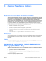
C
Agency Regulatory Notices
Federal Communications Commission Notice
This equipment has been tested and found to comply with the limits for a Class B digital device, pursuant
to Part 15 of the FCC Rules. These limits are designed to provide reasonable protection against harmful
interference in a residential installation. This equipment generates, uses, and can radiate radio
frequency energy and, if not installed and used in accordance with the instructions, may cause harmful
interference to radio communications. However, there is no guarantee that interference will not occur
in a particular installation. If this equipment does cause harmful interference to radio or television
reception, which can be determined by turning the equipment off and on, the user is encouraged to try
to correct the interference by one or more of the following measures:
●
Reorient or relocate the receiving antenna.
●
Increase the separation between the equipment and the receiver.
●
Connect the equipment into an outlet on a circuit different from that to which the receiver is
connected.
●
Consult the dealer or an experienced radio or television technician for help.
Modifications
The FCC requires the user to be notified that any changes or modifications made to this device that are
not expressly approved by Hewlett Packard Company may void the user's authority to operate the
equipment.
Cables
Connections to this device must be made with shielded cables with metallic RFI/EMI connector hoods
to maintain compliance with FCC Rules and Regulations.
Declaration of Conformity for Products Marked with the
FCC Logo (United States Only)
This device complies with Part 15 of the FCC Rules. Operation is subject to the following two conditions:
1.
This device may not cause harmful interference.
2.
This device must accept any interference received, including interference that may cause
undesired operation.
For questions regarding the product, contact:
ENWW
Federal Communications Commission Notice
27
Hewlett Packard Company
P. O. Box 692000, Mail Stop 530113
Houston, Texas 77269-2000
Or, call 1-800-HP-INVENT (1-800 474-6836)
For questions regarding this FCC declaration, contact:
Hewlett Packard Company
P. O. Box 692000, Mail Stop 510101
Houston, Texas 77269-2000
Or, call (281) 514-3333
To identify this product, refer to the Part, Series, or Model number found on the product.
Canadian Notice
This Class B digital apparatus meets all requirements of the Canadian Interference-Causing Equipment
Regulations.
Avis Canadien
Cet appareil numérique de la classe B respecte toutes les exigences du Règlement sur le matériel
brouilleur du Canada.
European Union Regulatory Notice
This product complies with the following EU Directives:
●
Low Voltage Directive 2006/95/EC
●
EMC Directive 2004/108/EC
Compliance with these directives implies conformity to applicable harmonized European standards
(European Norms) which are listed on the EU Declaration of Conformity issued by Hewlett-Packard for
this product or product family.
This compliance is indicated by the following conformity marking placed on the product:
This marking is valid for non-Telecom
products and EU harmonized Telecom
products (e.g. Bluetooth)
This marking is valid for EU nonharmonized Telecom products.
*Notified body number (used only if
applicable — refer to the product label).
28
Appendix C Agency Regulatory Notices
ENWW
Hewlett-Packard GmbH, HQ-TRE, Herrenberger Strasse 140, 71034 Boeblingen, Germany
German Ergonomics Notice
HP products which bear the “GS” approval mark, when forming part of a system comprising HP brand
computers, keyboards and monitors that bear the “GS” approval mark, meet the applicable ergonomic
requirements. The installation guides included with the products provide configuration information.
Japanese Notice
Korean Notice
Power Cord Set Requirements
The monitor power supply is provided with Automatic Line Switching (ALS). This feature allows the
monitor to operate on input voltages between 100–120V or 200–240V.
The power cord set (flexible cord or wall plug) received with the monitor meets the requirements for use
in the country where you purchased the equipment.
If you need to obtain a power cord for a different country, you should purchase a power cord that is
approved for use in that country.
The power cord must be rated for the product and for the voltage and current marked on the product's
electrical ratings label. The voltage and current rating of the cord should be greater than the voltage and
current rating marked on the product. In addition, the cross-sectional area of the wire must be a minimum
of 0.75 mm² or 18 AWG, and the length of the cord must be between 6 feet (1.8 m) and 12 feet (3.6 m).
If you have questions about the type of power cord to use, contact an authorized HP service provider.
A power cord should be routed so that it is not likely to be walked on or pinched by items placed upon
it or against it. Particular attention should be paid to the plug, electrical outlet, and the point where the
cord exits from the product.
Japanese Power Cord Requirements
For use in Japan, use only the power cord received with this product.
CAUTION:
ENWW
Do not use the power cord received with this product on any other products.
German Ergonomics Notice
29
Product Environmental Notices
Materials Disposal
This HP product contains mercury in the fluorescent lamp in the display LCD that might require special
handling at end-of-life.
Disposal of this material can be regulated because of environmental considerations. For disposal or
recycling information, contact the local authorities or the Electronic Industries Alliance (EIA)
http://www.eiae.org.
Disposal of Waste Equipment by Users in Private Household in the
European Union
This symbol on the product or on its packaging indicates that this product must not be disposed of with
your household waste. Instead, it is your responsibility to dispose of your waste equipment by handing
it over to a designated collection point for the recycling or waste electrical and electronic equipment.
The separate collection and recycling of your waste equipment at the time of disposal will help to
conserve natural resources and ensure that it is recycled in a manner that protects human health and
the environment. For more information about where you can drop off your waste equipment for recycling,
please contact the local city office, the household waste disposal service or the shop where you
purchased the product.
HP Recycling Program
HP encourages customers to recycle used electronic hardware, HP original print cartridges, and
rechargeable batteries. For more information about recycling programs, go to http://www.hp.com/
recycle.
Chemical Substances
HP is committed to providing our customers with information about the chemical substances in our
products as needed to comply with legal requirements such as REACH (Regulation EC No 1907/2006
of the European Parliament and the Council). A chemical information report for this product can be found
at: http://www.hp.com/go/reach
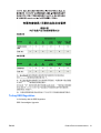
Restriction of Hazardous Substances (RoHS)
A Japanese regulatory requirement, defined by specification JIS C 0950, 2005, mandates that
manufacturers provide Material Content Declarations for certain categories of electronic products
offered for sale after July 1, 2006. To view the JIS C 0950 material declaration for this product, visit
http://www.hp.com/go/jisc0950.
30
Appendix C Agency Regulatory Notices
ENWW
11363-2006
11363-2006
Turkey EEE Regulation
In Conformity with the EEE Regulation
EEE Yönetmeliğine Uygundur
ENWW
Product Environmental Notices
31
D
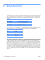
Native Resolution
The native resolution of a monitor is the resolution level at which the LCD panel is designed to perform
best. The native resolution is 1024 x 768 for the 15 inch size. In almost all cases, screen images look
best when viewed at their native resolution. You can lower the resolution setting of a monitor but not
increase it.
Input Video
15” LCD
640 x 480 (VGA\S)
Transforms input format to 1024 x 768
800 x 600 (SVGA)
Transforms input format to 1024 x 768
1024 x 768 (XGA)
Displays in Native Resolution
The native resolution of an LCD is the actual number of pixels horizontally in the LCD by the number of
pixels vertically in the LCD. LCD resolution is usually represented by the following symbols:
VGA
640 x 480
SVGA
800 x 600
XGA
1024 x 768
SXGA
1280 x 1024
UXGA
1600 x 1200
As an example, a SVGA resolution LCD panel has 800 pixels horizontally by 600 pixels vertically. Input
video is also represented by the same terms. XGA input video has a format of 1024 pixels horizontally
by 768 pixels vertically. When the input pixels contained in the video input format match the native
resolution of the panel, there is a one to one correspondence of mapping of input video pixels to LCD
pixels. As an example, the pixel in column 45 and row 26 of the input video is in column 45 and row 26
of the LCD. For the case when the input video is at a lower resolution than the native resolution of the
LCD, the direct correspondence between the video pixels and the LCD pixels is lost. The LCD controller
can compute the correspondence between video pixels and LCD pixels using algorithms contained on
its controller. The accuracy of the algorithms determines the fidelity of conversion of video pixels to LCD
pixels. Poor fidelity conversion can result in artifacts in the LCD displayed image such as varying width
characters.
32
Appendix D Native Resolution
ENWW