1
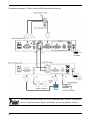
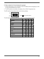
SERVIS Cat5 Extender Wide Band FE-2000CW User’s Manual FCC WARNING: Changes or modifications not expressly approved by the party responsible for compliance could void the user's authority to operate the equipment. This equipment has been tested and found to comply with the limits for a Class A digital device, pursuant to Part 15 of the FCC Rules. These limits are designed to provide reasonable protection against harmful interference when the equipment is operated in a commercial environment. This equipment generates, uses, and can radiate radio frequency energy and, if not installed and used in accordance with the instruction manual, may cause harmful interference to radio communications. Operation of this equipment in a residential area is likely to cause harmful interference in which case the user will be required to correct the interference at his own expense. This Product is designed, developed and manufactured as contemplated for general use, including without limitation, general office use, personal use, household use, and ordinary industrial use, but is not designed, developed and manufactured as contemplated for use accompanying fatal risks or dangers that, unless extremely high safety is secured, could lead directly to death, personal injury, severe physical damage or other loss (hereinafter "High Safety Required Use "), including without limitation, nuclear reaction control in nuclear facility, aircraft flight control, air traffic control, mass transport control, medical life support system, missile launch control in weapon system. You shall not use this Product without securing the sufficient safety required for the High Safety Required Use. If you wish to use this Product for High Safety Required Use, please consult with our sales representatives in charge before such use. Names and product names are the registered trademarks or trademarks of their respective companies. All Rights Reserved, Copyright© FUJITSU COMPONENT LIMITED 2005 Contents 1. PREFACE ·················································································································2 1.1 Conventions······································································································································· 2 1.2 Packing list ········································································································································ 3 2. IMPORTANT NOTICES ····························································································4 2.1 Safety················································································································································ 4 2.2 Disposal············································································································································· 6 2.3 Moving the Cat5 Wide Band··············································································································· 6 2.4 Compatible peripherals (keyboards, mice & monitors) ········································································ 6 3. NAMES AND FUNCTIONS OF EACH PART ···························································7 3.1 LOCAL (Transmitter Unit) ·················································································································· 7 3.2 REMOTE (Receiver Unit)··················································································································· 9 4. ATTACHING THE FERRITE CORES ·····································································11 5. CONNECTING THE CABLES·················································································12 5.1 Connecting cables ····························································································································12 6. SETTING UP THE CAT5 WIDE BAND ···································································16 6.1 Adjusting the Image Quality ··············································································································16 6.2 Adjusting the Color····························································································································17 6.3 How to Adjust for Various Keyboard Languages················································································18 7. REMOVING THE CABLES ·····················································································20 8. CLEANING THE CAT5 WIDE BAND······································································20 9. APPLICATION EXAMPLE ······················································································21 10. USING A TOUCH PANEL·······················································································22 11. TECHNICAL SPECIFICATIONS ·············································································23 12. TROUBLESHOOTING ····························································································25 1 1. Preface Thank you for your purchase of the SERVIS Cat5 Extender Wide Band. Use of the SERVIS Cat5 Extender Wide Band allows the server, keyboard, mouse, and monitor to be placed in separate locations, improving the amount of control the consumer has over the use of space in his/her work area. IA server and SUN server multiplatform compatible computers can be connected to this product. Video input from the server may use either separate sync or composite sync format. Use a multiscan monitors with a resolution of 1600 x 1200 pixels, and a refresh rate of 75Hz (maximum) to connect to the SERVIS Cat5 Extender Wide Band. Remote speakers can also be connected to create a rich audio environment, and a touch panel, etc. can be used via the RS-232C connector (serial port)*1. *1: Lack of flow control means that driver firmware, etc. may need to be changed. *Note: The SERVIS Cat5 Extender Wide Band is hereafter referred to as the "Cat5 Wide Band". 1.1 Conventions Symbols and terminology that are used in this manual are described below. CAUTION This symbol indicates the possibility of physical damage (such as damage to the Cat5 Wide Band or the server) or physical injury, which may result if the Cat5 Wide Band is operated incorrectly by ignoring this symbol. This logo indicates supplemental information, comments or hints. • • Text that is preceded by a number (such as 1.) indicates that the operation must be done in the order indicated. Reference to important chapter titles and terminology are in brackets [ ]. 2 1.2 Packing list Make sure that the items in the following list are included in the shipping package. • LOCAL (Transmitter Unit) x1 • REMOTE (Receiver Unit) x1 • AC Adapter x2 • User’s Manual (this manual) x1 • Masking Sticker x4 • Rubber Feet x8 • Cable Clamps x2 • Adjustment Stylus x1 • Ferrite Core x2 The packaging (box and contents) should be kept because it might be necessary to move the Cat5 Wide Band to some other place. If something is missing from the package, contact your supplier or local FUJITSU COMPONENT representative. CAUTION Please note the safety information in [Important Notices]. 1. Check the package delivered and whether the Cat5 Wide Band has been damaged when unpacking. 3 2. Important Notices This chapter contains cautions that must be taken when the Cat5 Wide Band is installed or used and information related to safety. Carefully read this chapter to use the Cat5 Wide Band correctly. 2.1 Safety CAUTION Precautions The Cat5 Wide Band adheres to the safety regulations related to information processing equipment such as electronic office machines that are used in an office environment. If you have any questions please contact your place of purchase or a FUJITSU COMPONENT maintenance engineer. To prevent extreme bumping or shaking when moving the Cat5 Wide Band use the original shipping container or a box similar to it. A squashed or broken box should not be used, as it may damage the Cat5 Wide Band. During installation and before using the Cat5 Wide Band, carefully read the [Installation] section and the section about environmental conditions in [Technical Specifications] for more on how to use the Cat5 Wide Band correctly. Moving the Cat5 Wide Band directly from a cold environment to the installation location may result in condensation occurring. Before using the Cat5 Wide Band allow it to dry out completely and to reach the ambient temperature of the installation location. Make sure that the local power supply voltage is within the acceptable range of the Cat5 Wide Band. (Refer to [Technical Specifications] and the model plate on the Cat5 Wide Band). Make sure that the area around the power supply outlet allows the Cat5 Wide Band to be freely plugged in and unplugged. Lay the cable in an area where it will not become damaged. Refer to the relevant sections in [Connecting Cables] / [Removing Cables] when plugging or unplugging the cables. Do not connect or remove the data transmission cables during thunderstorms. Do not allow foreign substances such as paperclips or other metal objects or liquids inside the Cat5 Wide Band. In an emergency (such as: damage to the housing, parts or cables; or liquid or a foreign object has fallen into the Cat5 Wide Band) remove the power cable as soon as possible and contact your place of purchase or FUJITSU COMPONENT representative (FUJITSU COMPONENT maintenance engineer). Only licensed engineers may repair the Cat5 Wide Band. Having unlicensed users attempt repairs may cause electric shock or fire. Do not attempt to repair or modify the Cat5 Wide Band yourself. Always hold the connector itself and do not jerk the cables when removing them. Do not plug or unplug connectors with wet hands. Do not place such unnecessary items as cups on the top of the Cat5 Wide Band. To prevent interference it is necessary to adequately isolate the data cables connected to peripheral equipment. Keep this manual with the Cat5 Wide Band. If you give the Cat5 Wide Band to a third party give them this manual also. 4 CAUTION Observe the following when using the Cat5 Wide Band: Familiarize yourself with the relevant safety precautions before using the Cat5 Wide Band. Observe the safety precautions provided herein. They contain important information intended to prevent accidents that could damage your property or cause you bodily harm. Make sure that the Cat5 Wide Band is turned OFF when plugging or unplugging connectors. Before plugging or unplugging connectors, discharge electricity, especially static electricity. Unplugging connectors without discharging static electricity or turning the power OFF presents a risk of damage to the server or the Cat5 Wide Band. Be advised that such damage is not covered by warranty. IA servers and SUN servers can be connected to the Cat5 Wide Band. All servers must be equipped with the keyboard, mouse, and monitor connectors listed below. This device cannot be used with other types of connectors. PS/2 keyboards and mice, USB keyboards and mice, and SUN keyboards cannot be connected to the console simultaneously. IA server : Mini DIN 6-Pin female x 2 (1 each for PS/2 keyboard, and PS/2 mouse use ) : USB A-type Connector : Mini D-Sub 15-Pin female (monitor) SUN : Mini DIN 8-Pin female : USB A-type Connector : Mini D-Sub 15-Pin female (monitor) The server is video signals may use either separate sync or composite sync. Check the monitor specification before setting the Cat5 Wide Band to separate sync or composite sync. Connect the Cat5 Wide Band and server with one of the optional CRT composite cables (PS/2, USB, SUN, 1.8m each, available separately). The Cat5 Wide Band will not function with unsupported keyboards (programmable, wireless) or mice (wireless, including those with special drivers) that have unique specifications. Select your peripherals accordingly. The Cat5 Wide Band is equipped with PS/2 (Mini DIN 6-Pin female), USB (A type), and SUN (Mini DIN 8-Pin female) keyboard connectors. The Cat5 Wide Band is equipped with PS/2 (Mini DIN 6-Pin female), and USB (A type) mouse connectors. Serial mice cannot be connected to the Cat5 Wide Band. Scroll wheel equipped PS/2 mice with unsupported scroll functions may not work correctly. Scroll functions may also not work correctly when used in conjunction with certain support software. PS/2 keyboards and PS/2 mice have identically shaped connectors. The color of the connectors should be different to allow them to be distinguished when making connections. Improperly connected peripherals will not only fail to function correctly, but may cause the Cat5 Wide Band to problem. Setup the console keyboard and server drivers correctly. The device will not function correctly if the settings are incorrect. (Example: Language drivers) The Cat5 Wide Band is not compatible with DVI (Digital Video Interface) monitors. The monitor cable is equipped with a Mini D-Sub 15-Pin connector. Confirm the direction of the connector and securely tighten the fastening screws. Improper connections could cause problems. 5 Connect a multiscan monitor to the Cat5 Wide Band and set the appropriate monitor resolution. Monitors supported by the Cat5 Wide Band may have a resolution of up to 1600 x 1200 pixels and a refresh rate of 75Hz. Image display may be affected by the monitor in use and changes made to resolution settings. If image display is poor, adjust the image settings at the monitor or video card. Image problems at high resolutions, as well as ghosting and bleeding with certain settings may be caused by the length of the Cat5 cable, the monitor cable, or the video card. Certain combinations of monitors and video cards may prevent proper image reproduction. To correct such problems, adjust the length of the Cat5 cable or adjust the video card preferences. Use only FUJITSU COMPONENT extenders when connecting LOCAL (transmitters) and/or REMOTE (receivers). The Cat5 Wide Band cannot be connected to extenders made by other manufacturers. 2.2 Disposal The Cat5 Wide Band is manufactured with metal and plastic parts. Dispose of it according the relevant government regulations. 2.3 Moving the Cat5 Wide Band CAUTION When moving the Cat5 Wide Band to a different location, use the box in which it was purchased or a box that protects the product from bumping and shaking. Do not unpack the Cat5 Wide Band until the move has been completed. 2.4 Compatible peripherals (keyboards, mice & monitors) 1. Keyboards • PS/2-compliant keyboards (101 - 109 keys) • USB (with HUB) keyboards (101 – 109 keys, SUN Type 6 USB keyboards) Novel device functions may not work. • SUN keyboards 2. Mice • PS/2-compliant mice (2-button, 3-button, Scroll Wheel Functions supported) • • − − − Microsoft/Inteli Mouse, Explorer Logicool/MouseMan+, MouseMan96, MouseMan Pilot Mouse MousePort USB mice (5-button, Scroll Wheel Functions supported, SUN Type 6 USB mice) Novel device functions may not work. SUN Mice 3. Monitors • Multiscan monitors for use with PC/AT compatibles *Note: Compatible with composite signals from the server. Check the server specifications. 6 3. Names and Functions of Each Part 3.1 LOCAL (Transmitter Unit) 1: Front panel (1) (2) (1) (2) POWER LED (green) This LED lights up while the machine is on, and blinks when the keyboard or mouse is used. USB status LED (green/red) The green LED lights up while the machine is on. Green LED on: USB keyboard and mouse are available. Red LED on: Over current. USB keyboard and mouse are not usable. Unplug the keyboard and mouse connectors (then turn the power OFF, and back ON to reset the Cat5 Wide Band). Both LEDs off: A device other than a USB keyboard or mouse is connected. Ensure that only a USB keyboard and mouse are connected. 2: Rear panel (3) (3) (4) (5) (6) 7 (4) (5) (6) (7) (8) (9) (10) (11) (12)(13) (14) Keyboard/Mouse (USB) connector Used to connect to a USB keyboard and mouse. Note that a USB hub function is not provided. RS232C connector Used to connect the server and the Cat5 Wide Band via an RS-232C cross cable (female - female). AUDIO In connector Stereo mini jack (φ 3.5) used to connect a server lineout. CONSOLE AUDIO OUT connector Stereo mini jack (φ 3.5) used to connect an amplifier speaker. (7) (8) (9) (10) (11) (12) (13) (14) Note: VIDEO CAT5 connector Used to connect to the receiver Video connector via a Cat5E cable. AUDIO CAT5 connector Used to connect to the receiver Audio connector via a Cat5E cable. SERVER connector (black) Use a CRT composite cable to connect the server to the Cat5 Wide Band. CONSOLE monitor connector (blue) Used to connect to the monitor. CONSOLE SUN connector (black) Used to connect a SUN keyboard. If another keyboard or mouse is connected to the receiver, both peripherals cannot be operated simultaneously. USB and PS/2 keyboards cannot be used in conjunction with SUN keyboards. CONSOLE mouse connector (green) Used to connect a PS/2 mouse. If another mouse is connected to the receiver, both mice cannot be operated simultaneously. USB mice cannot be used in conjunction with SUN mice. CONSOLE keyboard connector (purple) Used to connect a PS/2 keyboard. If another keyboard is connected to the receiver, both keyboards cannot be operated simultaneously. USB and PS/2 keyboards cannot be used in conjunction with SUN keyboards. DC5V connector Used to connect the dedicated AC adapter. Priority for SUN, USB, and PS/2 keyboards and mice when used in conjunction • When SUN, USB and PS/2 keyboards and mice are all connected simultaneously, only the SUN keyboard and mouse will be usable. • When USB and PS/2 keyboards and mice are connected simultaneously, only the USB keyboard and mouse will be useable. 8 3.2 REMOTE (Receiver Unit) 1: Front panel (1) (2) (3) (4) (1) (2) (3) (4) POWER LED (green) This LED lights up while the machine is on, and blinks when the keyboard or mouse is used. Focus knob Used to adjust the focus of the monitor. When a long Cat5E cable is used, turn it to the right. When short, turn it to the left until the monitor is focused. Brightness knob Used to adjust the brightness or the monitor. Turn it to the right to make the monitor brighter. Look at the edges of the characters to find the best position. USB status LED (green/red) The green LED lights up while the machine is on. Green LED on: USB keyboard and mouse are available. Red LED on: Over current. USB keyboard and mouse are not usable. Unplug the keyboard and mouse connectors (then turn the power OFF, and back ON to reset the Cat5 Wide Band). Both LEDs off: A device other than a USB keyboard or mouse is connected. Ensure that only a USB keyboard and mouse are connected. 2: Rear panel (5) (5) 9 (6) (7) (8) (9) (10) (11)(12)(13) (14) Keyboard/Mouse (USB) connector Used to connect to a USB keyboard and mouse. Note that a USB hub function is not provided. (6) (7) (8) (9) (10) (11) (12) (13) (14) Note: RS232C connector May be used to connect a touch panel. This connector has the same pin assignments as the server, and the same RS-232C cable as is used between the touch panel and server may be used. AUDIO Out connector Stereo mini jack (φ 3.5) used to connect an amplifier speaker. VIDEO CAT5 connector Used to connect to the transmitter via a Cat5E cable. AUDIO CAT5 connector Used to connect to the transmitter via a Cat5E cable. Monitor connector (blue) Used to connect to the monitor. SUN connector (black) Used to connect a SUN keyboard. If another keyboard or mouse is connected to the transmitter, both peripherals cannot be operated simultaneously. USB and PS/2 keyboards cannot be used in conjunction with SUN keyboards. CONSOLE mouse connector (green) Used to connect a PS/2 mouse. If another mouse is connected to the transmitter, both mice cannot be operated simultaneously. USB mice cannot be used in conjunction with SUN mice. Keyboard connector (purple) Used to connect a PS/2 keyboard. If another keyboard is connected to the transmitter, both keyboards cannot be operated simultaneously. USB and PS/2 keyboards cannot be used in conjunction with SUN keyboards. DC5V connector Used to connect the supplied AC adapter. Priority for SUN, USB, and PS/2 keyboards and mice when used in conjunction • When SUN, USB and PS/2 keyboards and mice are all connected simultaneously, only the SUN keyboard and mouse will be useable. • When USB and PS/2 keyboards and mice are connected simultaneously, only the USB keyboard and mouse will be useable. 10 4. Attaching the Ferrite Cores CAUTION Attach a ferrite core to the LOCAL (Transmitter Unit) side of the Cat5 cable (to decrease extraneous radiation.) Be careful not to pinch the cable or your fingers when closing and locking the ferrite core. Attach a ferrite core to each Video and Audio cable. If Audio is not used, a ferrite core will not need to be attached. 1. Loop the Cat5 cable once through the ferrite core, and lock it shut. *Attach the core no more than 20cm from the LOCAL (Transmitter Unit). 2. Be careful not to pinch the cable or your fingers when closing and locking the ferrite core. 11 5. Connecting the Cables CAUTION 1. Read the Cat5 Wide Band manual before connecting the cables. Do not connect or remove the cables during a thunderstorm. When unplugging cables hold them by the plug, not the cable. 2. Do not connect a LAN cable to the Cat5E port, it may be damaged. 3. If a touch panel is to be used, the touch panel driver must be installed before the touch panel is used. You should also pay appropriate attention to any cautions that pertain to use of the touch panel. 5.1 Connecting cables 1. Getting started Make sure that the server power cord is plugged into an outlet and that the server is turned off. (Confirm that (1) is connected.) 2. Connecting the LOCAL (Transmitter Unit) 2.1 Connect the CRT composite cable to the server's keyboard/mouse and the CRT connector. (Connect (2).) Next, connect the Server connector (Mini D-Sub 15-Pin female) to the dedicated connector (black). (Connect (3).) Securely fasten the Mini D-Sub 15-Pin with the fastening screws. 2.2 Connect the stereo mini jack (φ 3.5) if AUDIO is required. (Connect (4).) * Note: It is not necessary to connect this cable if you are not going to use audio. 2.3 Connect the D-Sub 9-Pin cross cable to the server's RS232C connector. (Connect (5).) * Note: It is not necessary to connect this cable if you are not going to use touch panel or etc. 2.3 Connect the Video Cat5E cable to the VIDEO connector (upper). (Connect (6).) 2.4 Connect the AUDIO Cat5E cable to the AUDIO connector (lower). (Connect (7).) * Note: It is not necessary to connect this cable if you are not going to use either audio or the RS232C. 3. Connecting the REMOTE (Receiver Unit) 3.1 When using a PS/2 keyboard or mouse (See connection example 1.) Connect the monitor, keyboard and mouse to the appropriate connectors. (Connect (8).) Note: The shapes of the keyboard and mouse connectors are identical. Be careful not to confuse them when making connections. 3.2 When using SUN keyboards (See connection example 2.) Connect the monitor, keyboard and mouse to the appropriate connectors. (Connect (8).) Note: The shapes of the SUN keyboard and PS/2 keyboard connectors are different. Be careful not to use excessive force when connecting keyboards. 3.3 Connect the Video Cat5E cable to the VIDEO connector (upper). (Connect (6).) 3.4 Connect the D-Sub 9-Pin cable to the RS232C connector. Next, connect the cable to the touch panel equipped monitor. (Connect (9).) * Note: It is not necessary to connect this cable if you are not going to use a touch panel or similar device. Check with the touch panel manufacturer for which RS232C cable you should use. 12 3.5 Connect the stereo mini jack to a speaker with internal amp (Connect (10).) * Note: It is not necessary to connect this cable if you are not going to use audio. 3.6 Connect the supplied AC adapter to the DC5V connector of the REMOTE (Receiver Unit) and plug the AC adapter into an outlet. (Connect (11).) 4. Connecting the AC adapter to the LOCAL (Transmitter Unit) 4.1 Connect the supplied AC adapter to the DC5V connector of the LOCAL (Transmitter Unit) and plug the AC adapter into an outlet. (Connect (12).) 13 Using the fastening screws, securely connect the monitor connector (Mini D-Sub 15-Pin) to the server. Image distortion may occur if the connector is not securely fastened. Connection example 1. When using a PS/2 keyboard and mouse 14 Connection example 2. When using a SUN keyboard and mouse The Cat5 Wide Band power up in the following order: receiver, transmitter, server. The power down order is as follows: server, transmitter, receiver. 15 6. Setting up the Cat5 Wide Band CAUTION 1. Read the instruction manual before making any settings on the Cat5 Wide Band. Incorrect settings may cause a severe drop in image quality. 2. Certain combinations of video cards and monitors may result in a poor quality image or displaced display area that cannot be compensated for by adjusting the Cat5 Wide Band the settings. In such cases, try a different resolution, or try adjusting the monitor itself. 6.1 Adjusting the Image Quality (1) (2) (3) (4) Turn the Brightness knob to give the brightness you want. Turn the Focus knob to obtain a sharp image. Adjust the color, if needed. Press the LCD monitor's Auto switch to check that the image quality is sharp (no color drift, no bleeding). When using the LCD monitor AUTO switch a plain white display helps the clock and phase to be adjusted. Example: Open and maximize a "Memo Pad" window before pressing the Auto switch. After adjusting the color, cover the DIP switches with the masking stickers that are included with the Cat5 Wide Band. 16 6.2 Adjusting the Color CAUTION (1) (2) (3) (4) (5) To adjust the color, remove the top cover from the delay line sliders. Be careful that no debris or foreign objects enter the delay line sliders while the cover is removed. Foreign objects in the delay line sliders can cause problems. Turn the REMOTE (Receiver Unit) upside down. Remove the transparent cover from the delay line sliders. Using the adjustment stylus, adjust the red, green, and blue delay line sliders by gently moving the tabs to the left or right. Do not exert excessive force when using the adjustment stylus. Doing so may damage the delay lines sliders. Reattach the transparent cover to the delay line sliders. After adjusting the color, cover the delay line sliders with the masking stickers that are included with the Cat5 Wide Band. Delay line sliders adjustment example (1) During adjustment of the delay line sliders, the onscreen background will be black with white vertical lines on it. The use of paint or other similar application software is recommended. (2) If the tab is moved in the "+" direction, green, red, or blue will move to the right. If the tab is moved in the "−" direction, green, red, or blue will move to the left. (3) At first, move the tab drastically to get a feel for color adjustment. After doing so, adjust the color in smaller increments. 17 6.3 How to Adjust for Various Keyboard Languages 1. Set the DIP switches on the Transmitter Unit in accordance with the language you wish to use on the keyboard of your choice. 2. The DIP switches are located on the bottom of the LOCAL (Transmitter Unit). The DIP switch settings shown below are the factory settings. ON OFF 1 2 3 4 Note: shows switch position. The following table shows the DIP switch settings for each keyboard language. Keyboard language No.1 No.2 No.3 No.4 Japanese ON ON ON ON UK ON ON ON OFF US ON ON OFF ON German ON ON OFF OFF French ON OFF ON ON Swedish ON OFF ON OFF Spanish ON OFF OFF ON Portuguese ON OFF OFF OFF Chinese (Taiwan) OFF ON ON ON Italian OFF ON ON OFF Korean OFF ON OFF ON UNIX OFF ON OFF OFF Norwegian OFF OFF ON ON Danish OFF OFF ON OFF Belgian OFF OFF OFF ON 18 ON OFF CAUTION 19 1 2 3 4 More on DIP switch settings If the DIP switches are not set properly for the keyboard you wish to use, you must reboot the server after correcting the DIP switch settings. 7. Removing the Cables For all equipment that is affected, unplug the power cables from the power outlets, then remove each cable. 8. Cleaning the Cat5 Wide Band CAUTION Turn off the power and unplug the power cable from the Cat5 Wide Band connector. Do not use cleansers that contain abrasives, or such organic solvents as benzene or thinner, or disinfectant alcohol. Do not apply water and cleanser or spray type cleaners directly to the Cat5 Wide Band. If liquids enter the interior of the Cat5 Wide Band it may result in problems or damage. Wipe the Cat5 Wide Band and monitor with a dry cloth. If the dirt is excessive, wipe it off with a soft cloth that has been thoroughly wrung out after being dipped in household cleanser diluted with water. Remove dust with a soft brush. 20 9. Application Example Connecting the Cat5 Wide Band to an 8 Port KVM Switch (FS-1008AT) Connecting the Cat5 Wide Band to a FUJITSU COMPONENT KVM Switch enhances expandability by making it possible to control multiple servers. 21 CAUTION Only connect the Cat5 Wide Band to KVM Switches manufactured by FUJITSU COMPONENT. It will not function properly if connected to KVM Switches made by a different manufacturer. The "KVM" in "KVM Switch" is an abbreviation for Keyboard, Video monitor, Mouse. 10. Using a Touch Panel CAUTION 1. The Cat5 Wide Band's RS-232C uses TXD and RXD only. Hardware handshaking only, so the driver firmware may needed to be changed. 2. Check with the manufacturer whether your touch panel can be used with TXD and RXD only. 1. When installing the touch panel driver (etc.) connect the touch panel directly to the server (do not connect it via the Cat5 Wide Band). 2. After checking that the touch panel works, adjust the driver firmware. (The details will differ for each touch panel manufacturer) Example: After installing the driver, the following settings must be adjusted. Modify the "HardwareHandshaking" registry parameter key. After setting up the driver, add a DWORD "HardwareHandshaking" value to the following registry key and set it to "0". This setting will be enabled after the server is rebooted. (Using "regedit") HKEY_LOCAL_MACHINE\SYSTEM \CurrentControlSet \Enum \SERNUM\ELOSERIAL \(Monitor ID Number) \Device Parameter 3. After adjusting the driver firmware, try connecting the touch panel via the Cat5 Wide Band. 22 11. Technical Specifications Item Name LED Display Interface Console Port Specification LOCAL (Transmitter Unit) REMOTE (Receiver Unit) POWER (green) USB STATUS (green/red) Keyboard Mouse SUN Serial USB Audio Transmitter and receiver connector Keyboard Mouse Monitor Server Port Distance Between Transmitter and Receiver Units Monitor Resolution, Refresh Rate Power Supply/ Power Consumption Ambient Temperature/Humidity for operation Ambient Temperature for storage Construction Size (W x D x H) Unit: mm Weight 23 1 1 2 2 PS/2 keyboard interface (OADG-compliant) PS/2 mouse interface (OADG-compliant) SUN keyboard/mouse-compliant USB keyboard/mouse Server lineout output FUJITSU COMPONENT original specification using 8-core RJ45 (Cat5) PS/2, Mini DIN 6-Pin female x 1 (purple) USB A type PS/2, Mini DIN 6-Pin female x 1 (green) USB A type Mini D-Sub 15-Pin female x 1 (blue) Mini D-Sub 15-Pin female x 1 (black) PS/2, Mini DIN 6-Pin female x 1 (purple) USB A type PS/2, Mini DIN 6-Pin female x 1 (green) USB A type Mini D-Sub 15-Pin female x 1 (blue) 1 to 300m 1600 x 1200 (Max.), 75Hz DC5V /0.8A (DC) DC5V /0.9A (DC) 0 to 40°C, 10 to 80%RH (no condensation) *Conforms to server operating conditions -20 to 60°C Painted (black) Metal case 220 x 120 x 42 220 x 127 x 42 About 0.9kg About 0.9kg Optional Accessories Item CRT composite cable (1.8m) CRT composite cable (1.8m) CRT composite cable (1.8m) Product ID NC14000-B002 NC14000-B102 NC14000-B202 Remark PS/2 cable USB cable SUN cable Item Cat5E cable Cat5E cable Cat5E cable Cat5E cable Cat5E cable Cat5E cable Product ID C5E-30 C5E-50 C5E-70 C5E-100 C5E-150 C5E-200 Remark Sky blue 30m cable Sky blue 50m cable Sky blue 70m cable Sky blue 100m cable Sky blue 150m cable Sky blue 200m cable Item Audio cable Product ID NC14004-B722 Remark Connects the server to the transmitter Item Rack mount panel Product ID NC14004-B323/B Remark 24 12. Troubleshooting Symptom Cause No image AC cord has come unplugged from displayed on either the outlet or the Cat5 Wide Band monitor Cat5 cable length setting is incorrect Keyboard/ Mouse functions improperly or not at all. USB keyboard/ mouse does not work Monitor is set to a resolution that is not supported Server not sending image signal (in suspend status) Improper key repeat settings Unsupported keyboard/mouse connected SUN, USB and PS/2 keyboard and mouse are all connected simultaneously USB status LED is off USB status LED is red Poor image quality (Ghosts, blurry letters, etc.) Poor connection/defective cable Cat5 cable length setting is incorrect STP (sealed type) cable is being used for the Cat5 to the VIDEO cable Image is not centered on screen 25 Remedy Connect the AC cord. Reset the length, using the section on setting Cat5 cable length in this manual as a reference. Set the monitor to a supported resolution. Input an image signal from the server. At the server, change the key repeat speed setting. Swap the peripheral in question for a supported keyboard/mouse. Simultaneous use of the SUN, USB and PS/2 keyboard and mouse is not possible. Connect one kind of keyboard and mouse only. A non-USB keyboard or mouse may be connected. Make sure that only a USB keyboard and mouse are connected. Over current detection circuit has triggered. Turn the Cat5 Wide Band power off and back on. If this happens frequently, contact your vendor. Confirm that the connector is connected properly. Use a different cable. If the problem goes away, exchange the defective cable with a good one. Reset the length, using the section setting Cat5 cable length in this manual as a reference. Lower resolution. Adjust monitor Use UTP type Cat5 cable for the VIDEO. Adjust the monitor. Cat5 Wide Band stopped working suddenly Touch panel does not work Cat5 Wide Band connection terminated Check the connection. Reboot the Cat5 Wide Band. Cat5 Extender stopped functioning Turn the power back on. (froze) Error occurred at server Remedy the server error. AC cable is unplugged from the outlet Connect the AC cable. or the Cat5 Wide Band RS-232C cable type does not match Use a cross cable between the server and the Cat5 Wide Band. Check that the touch panel specifications allow connection between the touch panel and the Cat5 Wide Band. Touch panel driver has not been Install the touch panel driver. installed When installing the driver, connect the touch panel directly to the server. Touch panel driver firm has not been Contact the touch panel adjusted manufacturer to check whether operation with TXD and RXD only is possible. If it is possible, modify the settings according to the manufacturer's directions. No sound Transmitter Audio Out has been Connect the Cat5 Wide Band to emitted connected to the server line out the Audio In port on the transmitter. Cat5 Audio cable has become Check the connection. detached or been connected to the Video connector Volume is set to 0 Turn the volume up. Server volume control is set to "mute" Turn off "mute" at the server volume control. If sound is emitted when speakers are connected to the Audio Out port on the transmitter, please contact your vendor. Spurious Environmental EM noise can cause Use STP (sealed type) Cat5E noise from spontaneous speaker noises. cable for the AUDIO line to reduce the speaker the noise. 26 Note Note Note SERVIS Cat5 Extender [FE-2000CW] User’s Manual Published July 2005 Published by FUJITSU COMPONENT LIMITED Printed in Japan ● The contents of this manual may be modified for improvements without prior notice. ● Fujitsu bears no responsibility for infringement of patent or other rights of third parties ascribable to the use of data in this manual. ● Reprinting of this manual without permission is prohibited. This manual is made of recycled paper. 050318 (NC14004-L545_R01)


![SERVIS Drawer 17inch [FD-1100AT] User`s Manual](http://vs1.manualzilla.com/store/data/005815433_1-e0ce1fd89f0d0c8bc9b31edbdc395367-150x150.png)
![SERVIS Console Drawer [ FD-1000AT ] User`s Manual](http://vs1.manualzilla.com/store/data/005855835_1-b5ddde4919c279623ac643a1427d1fab-150x150.png)