1
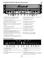
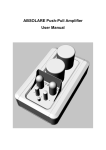
Valve Power Amps
&
EL84 20/20,
EL34 50/50
EL34 100/100
Marshall Amplification plc
Denbigh Road, Bletchley, Milton Keynes, MK1 1DQ, England
Tel: (01908) 375411
Fax: (01908) 376118
Web Site - http://www.marshallamps.com
Whilst the information contained herein is correct at the time of publication,
due to our policy of constant improvement and development, Marshall
Amplification plc reserve the right to alter specifications without prior notice.
Jan ‘99
Handbook
1
WARNING!
PLEASE READ THE FOLLOWING LIST CAREFULLY
A. ALWAYS fit a good quality mains plug conforming to the latest B.S.I. standards where necessary (UK only).
B. NEVER attempt to by-pass fuses or fit ones of the incorrect value.
C. NEVER attempt to replace fuses or valves with the amplifier connected to the mains.
D. DO NOT attempt to remove the amplifier chassis, there are no user serviceable parts.
E. ALWAYS have this equipment serviced or repaired by competent, qualified personnel.
F. NEVER use an amplifier in damp or wet conditions.
G. DO NOT switch the amplifier on without the loudspeaker connected.
H. ENSURE that any extension cabinets used are of the correct impedance.
I. WARNING: When fitted into a standard rack or flight case, ALWAYS ensure that the front and back of the
case are completely removed. For stand alone use, a clearance of 30cm is required at the top, back and sides.
J. PLEASE read this instruction manual carefully before switching on.
WARNING : This apparatus must be earthed.
Introduction
Models EL84 20/20, EL34 50/50 and EL34 100/100 stereo valve power amplifiers are the latest step forward in valve
rack technology from Marshall. Built as dedicated guitar system based units, they incorporate many features that are
both revolutionary and evolutionary. From stunning styling, through to the radical circuit design, these power amps are
in a sonic class of their own.
EL84 20/20
The EL84 20/20 is the latest all valve power amp from Marshall and utilises EL84 power valves to obtain that classic
british tone, famous since the birth of British rock guitar in the early sixties. Despite its compact size and modest power
rating, the 20/20 packs a big punch, both sonically and in terms of features. Carefully designed to maximise clean
headroom and also endowed with superb overload capability, the 20/20 is ideal for compact rack rigs, for both sessions
and club gigs alike. When miked up on larger concert stages it will provide pure valve tone with the minimum of stage
spill.
The remotely switchable deep switch can be used to alter the sonic character of your pre-amp patches to great effect.
Also the innovative valve line stage, at the input of each channel, helps to give true valve warmth to even the most sterile
sounding pre-amp. The EL84 20/20 is a compact powerhouse which can greatly enhance the tonal palette of any rack rig.
EL34 50/50 & EL34 100/100
With the EL34 50/50 and EL34 100/100 the specially designed Marshall ‘Gold’ front panel provides a deep recess in
which the controls are sited giving a smooth uncluttered finish, whilst allowing the controls to be set, with little fear of
accidental re-adjustment. The two power amp halves of your EL34 50/50 or EL34 100/100 are totally separate
‘MonoBlocs’, a feature that is normally only found on expensive valve hi-fi power amps. This means that the only
common electrical item (apart from when specifically cross linking inputs) is the mains supply and that nothing that
occurs to one power amp can sonically react with the other half. Also in the unlikely event of one side breaking down,
the other side will carry on working regardless.
Our constant research into valve amplifier technology has resulted in further circuit design improvements which
dramatically affect the overall feel and playing response of your Marshall valve power amp. These improvements
include Marshalls latest True Differential Inverter technology, which expands the capability of the phase splitter
(inverter). Put simply, the phase splitter takes the incoming signal and inverts half of it. This inverted half of the signal
forms the bottom half of the sound envelope and the non-inverted half forms the top half. The effect of T.D.I. technology
is to give a more defined spectrum of sound over a broader band width, without compromising the overdrive and
compression effects for which valve amplifiers are famed. This also allows more radical uses of feedback networks and
the incorporation of the ‘voicing’ switching found on each channel. These incredible ‘voicing’ options, which can be
remotely activated, can be used to greatly expand your pre-amps tone forming at the flick of a switch.
Mounting the Power Amp in a Rack
To allow the secure fastening of 19 inch rack units in a rack enclosure, a series of mounting holes are provided on the
front of the EL84 20/20 and on both the front and rear of the EL34 50/50 and EL34 100/100. As with all rack mount
products of substantial weight, such as the EL34 50/50 & 100/100, the rear of the unit must be supported as well as the
front, therefore suitable brackets should be obtained and fitted between the provided rear mountings and the rack case. It
should always be remembered that valve amplifiers generate a certain amount of heat, therefore they should never be
mounted, or used, in any situation without adequate airflow.
2
EL84 20/20 Front Panel Features
PRESENCE
LEVEL
OFF
OFF
EL84 20/20
STEREO VALVE POWER AMPLIFIER
0
10
0
10
1
1. Level
2
3
STANDBY
4
STANDBY
POWER
5
7. Power
Adds brightness and top end bite to your
On/Off Switch for mains power to the
Note: To prolong the life of the valves it is always
advisable to switch on the Mains Power Switch (item 7)
about 1 minute before switching on the Standby (item 6).
This allows the valves to heat up to full working
temperature before use.
On switching off, the Standby should always be
switched before the Power Switch.
3. Deep The Deep switch on the 20/20 affects the
speaker damping. By depressing the Deep switch you will
add more bottom end thud to your guitar sound. Similar to
the difference between open and closed back cabinets.
Indicates operating status of standby
(see 6).
5. Power LED
7
amplifier.
sound.
4. Standby LED
POWER
6
Controls Level or volume of the EL84 20/20.
2. Presence
ON
ON
DEEP
The standby facility is particularly useful live, where
before playing and between sets, it allows you to keep the
valves operating at a slightly reduced temperature but
without any sound being produced.
Indicates operating status of amp
(see 7).
6. Standby
Controls the H.T. supply to the valves and
allows the valves to remain heated when not in use.
EL84 20/20 Rear Panel Features
MAINS INPUT
LEFT OUTPUTS
2x20 Watts RMS
POWER OUTPUT
INTO 8/16 Ω
120V ~ 60Hz
220 WATTS
16Ω
1
2
SPEAKER
RIGHT OUTPUTS
8Ω
LINE
16Ω
3
4
5
1. Mains Input Connects the amplifier to the mains
SPEAKER
8Ω
6
REMOTE SWITCHING
LINE
7
INPUTS
DEEP
LEFT
RIGHT(MONO)
8
9
10
power supply.
Note: When the 20/20 is in use, speakers must be
connected to both sides at all times. See Loading points
Left Outputs
Loading Points
-The 20/20 delivers 2x20 Watts into 8 or 16 Ohms.
2. 16 Ohm Jack Speaker jack for 16 Ohm speaker
cabinet for left side of power amp.
3. 8 Ohm Jack Speaker jack for 8 Ohm speaker
cabinet for left side of power amp.
4. Line Attenuated version of speaker signal giving
whole tone of power stage. For connection to subsequent
effects processor and larger power amp.
Note:
When 20/20 is in use, speakers must be connected
to both sides at all times. See Loading points later.
Right Outputs
5. 16 Ohm Jack
Speaker jack for 16 Ohm speaker
cabinet for right side of power amp.
6. 8 Ohm Jack
Speaker jack for 8 Ohm speaker cabinet
for right side of power amp.
7. Line Attenuated version of speaker signal giving
whole tone of power stage. For connection to subsequent
effects processor and larger power amp.
-The 20/20 must have either an 8 Ohm or 16 Ohm
speaker connected to either side. Under no circumstances
should both the 8 and 16 Ohm sockets of the same side be
used together.
-The 20/20 must have speakers connected to both sides
when in use.
Remote Switching
8. Deep In addition to the front panel, the Deep facility
can be switched remotely by a footswitch or
programmable device, such as an effects processor.
It should be noted that this will override the front panel
switch position.
Inputs
9. Left
Takes the left input from a stereo pre-amp.
10. Right (Mono)
Takes the right input from a stereo
pre-amp, or the mono input from a mono pre-amp.
A mono input will drive both channels.
3
EL34 50/50 & EL34 100/100 Front Panel Features
EL34 50/50
A
1
2
3
17
B
Dual MonoBloc Amplifier
5
6
7
8
9
10
11
12
4
14 15
16
13
1. Channel A mains power rocker switch
8. Channel A gain control Rotary control to set and
balance the incoming signal level.
Connects channel A to incoming mains supply.
LED 3 indicates red when activated.
9. Channel B gain control
2. Channel A standby switch Connects channel A's
10. Channel B presence control
high voltage circuit to the power supply.
LED 4 indicates green when activated.
11. Channel B voice switch
Note! To conserve valve life, standby switch 2 should
12. Channel B voice LED
remain off for at least 1 minute after powering up the
amplifier.
13. Channel B standby LED
3/4. Mains & standby LED's.
5. Voice B LED Indicates red when channel A's voicing
14. Channel B mains LED
option B is activated.
15. Channel B standby switch
6. Channel A voice toggle switch Selects voice
16. Channel B mains switch
option A or B, this function is repeated on a remote
switching jack on the rear panel (see rear panel
functions). The switch should be in the B position for the
remote switch to be operative.
Note! Channel A's notes also apply.
17. Front rack mount fixing holes.
7. Channel A presence control Rotary control to
boost the upper mid to high frequency content of sound.
Rear Panel Features
WARNING! No user serviceable parts
inside; refer servicing to qualified
personnel only.
AVIS! Risque de choc. Ne pas ouvrir.
WARNING! Fire & Shock Hazard: Do not
expose this unit to rain or moisture. This
Apparatus Must Be Earthed. Do not open
MAINS INPUT
MAINS FUSE
120V ~ 60Hz
115 V- T3. 15A
230V -T1.6A
350 VA
1
CH B
2
CH A
3
4
Made in England by: Marshall Amplification plc, Bletchley, Milton Keynes.
SEE MANUAL FOR CORRECT OPERATION AND RATING
EL34 50/50
OUTPUT
SELECT Ω
CH A
5
6
7
T315mA
CH B
DO NOT USE WITHOUT CONNECTING SPEAKER LOAD
CH B
LOUDSPEAKER
OUTPUT
HT FUSE
16
8
OUTPUT
SELECT Ω
16
8
8
REMOTE VOICE
SWITCHING
CH A
LOUDSPEAKER
OUTPUT
9
(SHORT TO GROUND) USE 'A'
ONLY TO SWITCH BOTH
CHANNELS
CH B
10
SIGNAL INPUT
USING INPUT 'A' ONLY GIVES DUAL MONO OPERATION (A+B)
WARNING OUTPUT A & B MUST HAVE INDIVIDUAL LOADS IN THIS MODE
CH A
LINK
11
12
CH B
INPUT
13
CH A
INPUT
14
LINK
15
1. Mains input socket Connects amplifier to
4. Channel B H.T. fuse Please see specifications for
incoming mains supply.
correct ratings.
2. Channel B mains fuse Please see specifications for
5. Channel A H.T. fuse Please see specifications for
correct ratings.
correct ratings.
3. Channel A mains fuse Please see specifications for
6. Channel B loudspeaker jacks Connects channel B
correct ratings.
to loudspeaker load - model EL34 50/50 - 50 watts RMS,
model EL34 100/100 - 100 watts RMS.
4
7. Channel B output impedance select 16 Ohm or
Note! Using 14 only connects input signal to both
8 Ohm - it is important that your amplifier and loudspeaker
load are correctly matched.
channels A & B for parallel mono operation.
15. Channel A link out jack Connects channel A
Note! If 4 Ohm output is desired please consult your
input signal to further power amp inputs.
authorised Marshall agent.
Valve Location Guide
8. Channel A output impedance select
(See 7 for notes).
Rear Mounting Fixing Hole
9. Channel A loudspeaker jacks
(See 6 for notes).
Rear Mounting Fixing Hole
Not Fitted To EL34 50/50
OUTPUT
TRANSFORMER
10,11. Remote voicing switching jacks
10 operates on channel B, 11 operates on channel A.
Short to ground function. Using jack 11 only links
channel A & B switching functions for simultaneous use.
@@@@@@@@e?@@@@@@@@e?@@@@@@@@?e@@@@@@@@e?@@@@@@@@?e@@@@@@@@e?@@@@@@@@?e@@@@@@@@e?@@@@@@@@?e@@@@@@@@e?@@@@@@@@?e@@@@@@@@e?@@@@@@@@?e@@@@@@@@e?@@@@@@@@?e@@@@@@@@e?@@@@@@@@?e@@@@@@@@e?@@@@@@@@?e@@@@@@@@e?@@@@@@@@?e@@@@@@@@e?@@@@@@@@?e@@@@@@@@e?@@@@@@@@?e@@@@@@@@e?
@@@@@@@@e?
@@@@@@@@
@@
@@h?@@@@@@@@e?@@@@@@@@?e@@@@@@@@e?@@@@@@@@?e@@@@@@@@e?@@@@@@@@?e@@@@@@@@e?@@@@@@@@?e@@@@@@@@e?@@@@@@@@?e@@@@@@@@e?@@@@@@@@?e@@@@@@@@e?@@@@@@@@?e@@@@@@@@e?@@@@@@@@?e@@@@@@@@e?@@@@@@@@?e@@@@@@@@e?@@@@@@@@?e@@@@@@@@e?@@@@@@@@?e@@@@@@@@e?@@@@@@@@?e@@@@@@@@e?@@@@@@@@
@@
@@h?
@@
@@h?
@@
@@h?
@@
@@h?
@@
@@h?
@@
@@
@@
@@
@@
@@
@@
@@
@@
@@
@@
@@
@@
@@
@@
@@
@@
@@
@@
@@
@@
@@
@@
@@
@@
@@
@@
@@
@@
@@
@@
@@
@@
@@
@@
@@
@@
@@
@@
@@
@@
@@
@@
@@
@@
@@
@@
@@
@@
@@
@@
@@
@@
@@
@@
@@
@@
@@
@@
@@
@@
@@
@@
@@
OUTPUT
TRANSFORMER
EL34
EL34
EL34
EL34
@@
@@
@@
@@
@@
@@
@@
@@
@@
@@
@@
@@
@@
@@
@@
@@
@@
@@
@@
@@
@@
@@
@@
@@
@@
@@
@@
@@
@@
@@
@@
@@
@@g
?@@
@@g
?@@
@@g
?@@
@@g
?@@
@@g
?@@
@@g
?@@
@@@@@@@@
@@@@@@@@ ?@@@@@@@@?e@@@@@@@@e?@@@@@@@@?e@@@@@@@@e?@@@@@@@@?e@@@@@@@@e?@@@@@@@@?e@@@@@@@@e?@@@@@@@@?e@@@@@@@@e?@@@@@@@@?e@@@@@@@@e?@@@@@@@@?e@@@@@@@@e?@@@@@@@@?e@@@@@@@@e?@@@@@@@@?e@@@@@@@@e?@@@@@@@@?e@@@@@@@@e?@@@@@@@@?e@@@@@@@@e?@@@@@@@@?e@@@@@@@@e?@@@@@@@@
?@@@@@@@@?e@@@@@@@@e?@@@@@@@@?e@@@@@@@@e?@@@@@@@@?e@@@@@@@@e?@@@@@@@@?e@@@@@@@@e?@@@@@@@@?e@@@@@@@@e?@@@@@@@@?e@@@@@@@@e?@@@@@@@@?e@@@@@@@@e?@@@@@@@@?e@@@@@@@@e?@@@@@@@@?e@@@@@@@@e?@@@@@@@@?e@@@@@@@@e?@@@@@@@@?e@@@@@@@@e?@@@@@@@@?e@@@@@@@@e?@@@@@@@@ ?@@@@@@@@
?@@@@@@@@
12. Channel B link out jack Connects channel B
input signal to further power amp inputs.
EL34
EL34
EL34
EL34
ECC81
ECC83
ECC83
ECC81
12AT7
12AX7
12AX7
12AT7
MAINS
TRANSFORMER
MAINS
TRANSFORMER
13. Channel B input jack Accepts input from preamp.
FRONT
14. Channel A input jack Accepts input from preamp.
Specification Chart
Parameter
EL34 50/50
EL34 100/100
Notes
Size
19" 3U x 331mm deep
19" 3U x 331mm deep
The unit must be supported at
the rear when mounted in a rack
Weight
29.5 kg
34.5 kg
Power input
350 watts
700 watts
Voltage Input
115V or 230V
115V or 230V
Consult amp rating plate or dealer
Frequency
50 or 60 Hz
50 or 60 Hz
Consult amp rating plate or dealer
Mains fuses
T3.15A/115V
T4A/115V
Per channel
T1.6A/230V
T2A/230V
Per channel
H.T. Fuses
T315 mA
T1A
Per channel
Output Power
50W RMS
100W RMS
At clipping (per channel)
Output Impedance
8 or 16 Ohm*
8 or 16 Ohm*
Consult dealer for 4 Ohm
Input sensitivity
OdB
OdB
Input impedance
20KΩ
20KΩ
Output valve
2 x EL34
4 x EL34
Per channel
Phase inverter
1 x ECC81/12 AT7
1 x ECC81/12 AT7
Per channel
Pre Driver
1 x ECC83/12 AX7
1 x ECC83/12 AX7
Per channel
5