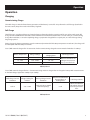
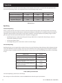
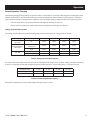
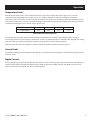
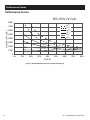
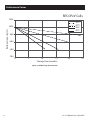
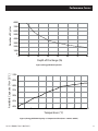
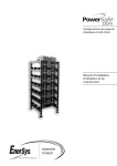
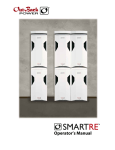
1
EnergyCell OPzV
Batteries
User’s Manual
About OutBack Power Technologies
OutBack Power Technologies is a leader in advanced energy conversion technology. Our products include true sine
wave inverters/chargers, maximum power point tracking charge controllers, and system communication components,
as well as circuit breakers, accessories, and assembled systems.
Contact Information
Address:
Corporate Headquarters
17825 - 59th Avenue N.E.
Suite B
Arlington, WA 98223 USA
European Office
Hansastrasse 8
D-91126
Schwabach, Germany
Telephone:
+1.360.435.6030
+1.360.618.4363 (Technical Support)
+1.360.435.6019 (Fax)
+49.9122.79889.0
+49.9122.79889.21 (Fax)
Email:
[email protected]
Website:
http://www.outbackpower.com
Disclaimer
UNLESS SPECIFICALLY AGREED TO IN WRITING, OUTBACK POWER TECHNOLOGIES:
(a) MAKES NO WARRANTY AS TO THE ACCURACY, SUFFICIENCY OR SUITABILITY OF ANY TECHNICAL OR OTHER
INFORMATION PROVIDED IN ITS MANUALS OR OTHER DOCUMENTATION.
(b) ASSUMES NO RESPONSIBILITY OR LIABILITY FOR LOSS OR DAMAGE, WHETHER DIRECT, INDIRECT, CONSEQUENTIAL
OR INCIDENTAL, WHICH MIGHT ARISE OUT OF THE USE OF SUCH INFORMATION. THE USE OF ANY SUCH INFORMATION
WILL BE ENTIRELY AT THE USER’S RISK.
Notice of Copyright
EnergyCell OPzV User’s Manual © August 2015 by OutBack Power Technologies. All Rights Reserved.
Trademark
OutBack Power and the OutBack Power logo are trademarks owned and used by OutBack Power Technologies, Inc.
The ALPHA logo and phrase “member of the Alpha Group” are trademarks owned and used by Alpha Technologies Inc.
These trademarks may be registered in the United States and other countries.
Date and Revision
August 2015, Revision A
Part Number
181-411-B0-001, Rev. A (08/2015)
Table of Contents
Important Safety Instructions . . . . . . . . . . . . . . . . . . . . . . . . . . . . . . . . . . . . . . . . . . . . . . . . . . . 5
Additional Resources . . . . . . . . . . . . . . . . . . . . . . . . . . . . . . . . . . . . . . . . . . . . . . . . . . . . . . 5
Delivery and Storage . . . . . . . . . . . . . . . . . . . . . . . . . . . . . . . . . . . . . . . . . . . . . . . . . . . . . . . . . 6
Receiving Inspection . . . . . . . . . . . . . . . . . . . . . . . . . . . . . . . . . . . . . . . . . . . . . . . . . . . . . . 6
Storage . . . . . . . . . . . . . . . . . . . . . . . . . . . . . . . . . . . . . . . . . . . . . . . . . . . . . . . . . . . . . . . 6
Unpacking and Handling . . . . . . . . . . . . . . . . . . . . . . . . . . . . . . . . . . . . . . . . . . . . . . . . . . . . 6
Installation . . . . . . . . . . . . . . . . . . . . . . . . . . . . . . . . . . . . . . . . . . . . . . . . . . . . . . . . . . . . . . . 7
Room and Installation Design . . . . . . . . . . . . . . . . . . . . . . . . . . . . . . . . . . . . . . . . . . . . . . . . . 7
Racks and Mechanical Stability . . . . . . . . . . . . . . . . . . . . . . . . . . . . . . . . . . . . . . . . . . . . . . . . 7
Cells in Parallel Strings . . . . . . . . . . . . . . . . . . . . . . . . . . . . . . . . . . . . . . . . . . . . . . . . . . . . . 7
Preliminary Inspection . . . . . . . . . . . . . . . . . . . . . . . . . . . . . . . . . . . . . . . . . . . . . . . . . . . . . 7
Electrical Connections . . . . . . . . . . . . . . . . . . . . . . . . . . . . . . . . . . . . . . . . . . . . . . . . . . . . . . 8
Instrumentation . . . . . . . . . . . . . . . . . . . . . . . . . . . . . . . . . . . . . . . . . . . . . . . . . . . . . . . . . 8
Operation . . . . . . . . . . . . . . . . . . . . . . . . . . . . . . . . . . . . . . . . . . . . . . . . . . . . . . . . . . . . . . . . 9
Charging . . . . . . . . . . . . . . . . . . . . . . . . . . . . . . . . . . . . . . . . . . . . . . . . . . . . . . . . . . . . . . 9
Commissioning Charge . . . . . . . . . . . . . . . . . . . . . . . . . . . . . . . . . . . . . . . . . . . . . . . . . . 9
Full Charge . . . . . . . . . . . . . . . . . . . . . . . . . . . . . . . . . . . . . . . . . . . . . . . . . . . . . . . . . . 9
Equalizing . . . . . . . . . . . . . . . . . . . . . . . . . . . . . . . . . . . . . . . . . . . . . . . . . . . . . . . . . . 10
Normal Operation Charging . . . . . . . . . . . . . . . . . . . . . . . . . . . . . . . . . . . . . . . . . . . . . . 11
Discharging . . . . . . . . . . . . . . . . . . . . . . . . . . . . . . . . . . . . . . . . . . . . . . . . . . . . . . . . . . . 12
Overdischarge Protection . . . . . . . . . . . . . . . . . . . . . . . . . . . . . . . . . . . . . . . . . . . . . . . . 12
Low-voltage Reconnect for Stand-Alone Systems . . . . . . . . . . . . . . . . . . . . . . . . . . . . . . . . . 12
Temperature Limits . . . . . . . . . . . . . . . . . . . . . . . . . . . . . . . . . . . . . . . . . . . . . . . . . . . . . . 13
Current Limits . . . . . . . . . . . . . . . . . . . . . . . . . . . . . . . . . . . . . . . . . . . . . . . . . . . . . . . . . . 13
Ripple Currents . . . . . . . . . . . . . . . . . . . . . . . . . . . . . . . . . . . . . . . . . . . . . . . . . . . . . . . . . 13
Battery Maintenance . . . . . . . . . . . . . . . . . . . . . . . . . . . . . . . . . . . . . . . . . . . . . . . . . . . . . . . . 14
Faults . . . . . . . . . . . . . . . . . . . . . . . . . . . . . . . . . . . . . . . . . . . . . . . . . . . . . . . . . . . . . . . . . . 15
Testing . . . . . . . . . . . . . . . . . . . . . . . . . . . . . . . . . . . . . . . . . . . . . . . . . . . . . . . . . . . . . . . . . 15
Taking Out of Operation / Storage . . . . . . . . . . . . . . . . . . . . . . . . . . . . . . . . . . . . . . . . . . . . . . . 15
Transport . . . . . . . . . . . . . . . . . . . . . . . . . . . . . . . . . . . . . . . . . . . . . . . . . . . . . . . . . . . . . . . 15
Performance Curves . . . . . . . . . . . . . . . . . . . . . . . . . . . . . . . . . . . . . . . . . . . . . . . . . . . . . . . . 16
Technical Specifications . . . . . . . . . . . . . . . . . . . . . . . . . . . . . . . . . . . . . . . . . . . . . . . . . . . . . . 20
Figures
Figure 1, Expected Number of Cycles vs Depth of Discharge . . . . . . . . . . . . . . . . . . . . . . . . . . . . . . . 16
Figure 2, Guidance for the Initial Low-Voltage Disconnect Settings (25°C Reference Temperature) . . . . . . 17
Figure 3, Self-Discharge Characteristics . . . . . . . . . . . . . . . . . . . . . . . . . . . . . . . . . . . . . . . . . . . . 18
Figure 4, EnergyCell OPzV Cycle Life . . . . . . . . . . . . . . . . . . . . . . . . . . . . . . . . . . . . . . . . . . . . . . 19
Figure 5, EnergyCell OPzV Capacity vs. Temperature Chart (Rate = 120Hr/1.85VPC) . . . . . . . . . . . . . . . . 19
Tables
Table 1, Case 1 . . . . . . . . . . . . . . . . . . . . . . . . . . . . . . . . . . . . . . . . . . . . . . . . . . . . . . . . . . . . . 9
Table 2, Case 2 . . . . . . . . . . . . . . . . . . . . . . . . . . . . . . . . . . . . . . . . . . . . . . . . . . . . . . . . . . . . . 9
Table 3, Case 3 . . . . . . . . . . . . . . . . . . . . . . . . . . . . . . . . . . . . . . . . . . . . . . . . . . . . . . . . . . . . 10
Table 4, Battery State Deviation . . . . . . . . . . . . . . . . . . . . . . . . . . . . . . . . . . . . . . . . . . . . . . . . . 10
Table 5, Settings for Stand-Alone Systems . . . . . . . . . . . . . . . . . . . . . . . . . . . . . . . . . . . . . . . . . . 11
Table 6, Functional Equalizing Frequency . . . . . . . . . . . . . . . . . . . . . . . . . . . . . . . . . . . . . . . . . . . 11
Table 7, Minimum Safe Temperature . . . . . . . . . . . . . . . . . . . . . . . . . . . . . . . . . . . . . . . . . . . . . . 13
Table 8, Performance Data - Discharge Constant Current at 20°C (Amperes) . . . . . . . . . . . . . . . . . . . . . 20
Table 8, Performance Data - Discharge Constant Current at 20°C (Amperes), Continued . . . . . . . . . . . . . 21
Table 9, Performance Data - Discharge Constant Power at 20°C (Watts/cell) . . . . . . . . . . . . . . . . . . . . . 22
Table 9, Performance Data - Discharge Constant Power at 20°C (Watts/cell), Continued . . . . . . . . . . . . . 23
Important Safety Information
Important Safety Instructions
READ AND SAVE THESE INSTRUCTIONS!
This manual contains important safety instructions for the EnergyCell OPzV battery. These instructions are in addition to the safety
instructions published for use with all OutBack products. Read all instructions and cautionary markings on the EnergyCell OPzV
battery and on any accessories or additional equipment included in the installation. Failure to follow these instructions could
result in severe shock or possible electrocution. Use extreme caution at all times to prevent accidents.
WARNING: Personal Injury
»»
Some batteries can weigh in excess of 100lb (45kg). Use safe lifting techniques
when lifting this equipment as prescribed by the Occupational Safety and
Health Association (OSHA) or other local codes. Lifting machinery may be
recommended as necessary.
»»
Wear appropriate protective equipment when working with batteries, including
eye or face protection, acid-resistant gloves, an apron, and other items.
»»
Wash hands after any contact with the lead terminals or battery electrolyte.
WARNING: Explosion, Electrocution, or Fire Hazard
»»
Ensure clearance requirements are strictly enforced around the batteries.
»»
Ensure the area around the batteries is well ventilated and clean of debris.
»»
Never smoke or allow a spark or flame near the batteries.
»»
Always use insulated tools. Avoid dropping tools onto batteries or other
electrical parts.
»»
Keep plenty of fresh water and soap nearby in case battery acid contacts skin,
clothing, or eyes.
»»
Wear complete eye and clothing protection when working with batteries.
Avoid touching bare skin or eyes while working near batteries.
»»
If battery acid contacts skin or clothing, wash immediately with soap and
water. If acid enters the eye, immediately flood it with running cold water for
at least 20 minutes and get medical attention as soon as possible.
»»
Never charge a frozen battery.
»»
Insulate batteries as appropriate against freezing temperatures. A discharged
battery will freeze more easily than a charged one.
»»
If a battery must be removed, always remove the grounded terminal from the
battery first. Make sure all devices are de-energized or disconnected to avoid
causing a spark.
»»
Do not perform any servicing other than that specified in the installation
instructions unless qualified to do so.
Additional Resources
These references may be used when installing this equipment. Depending on the nature of the installation, it may be highly
recommended to consult these resources.
Institute of Electrical and Electronics Engineers (IEEE) guidelines: IEEE 450, IEEE 484, IEEE 1184, IEEE 1187, IEEE 1188, IEEE 1189,
IEEE 1491, IEEE 1578, IEEE 1635, and IEEE 1657 (various guidelines for design, installation, maintenance, monitoring, and safety of
battery systems)
181-411-B0-001, Rev. A (08/2015)
5
Delivery and Storage
Delivery and Storage
Receiving Inspection
Inspect the shipment for missing components. Verify the contents with the packaging documents. Inspect each package or pallet
for integrity and electrolyte leakage. Record the receipt date and the inspection results, and notify OutBack Power of any damage.
Take photographs if necessary.
Storage
»»
Store the batteries in a dry, clean, cool, and well ventilated location. Do not expose the cells to direct sunlight as damage
to the container and cover may occur.
»»
Do not stack one pallet above the other. Avoid storing unpacked cells / monoblocs on sharp-edged supports.
»»
Storage on a pallet wrapped in plastic material is permitted except in rooms where the temperature fluctuates
significantly, or if high relative humidity can cause condensation under the plastic cover. With time, this condensation can
cause a whitish hydration on the poles and lead to high self-discharge by leakage current.
»»
Protect the batteries from any risk of electric shock resulting from short-circuiting by a conductive object or from a
building up of conductive dust.
»»
It is recommended to have the same storage conditions within a batch, pallet or room.
»»
As the batteries are supplied charged, storage time is limited. In order to easily charge the batteries after prolonged
storage, it is advised not to store them more than 6 months at 20°C, 4 months at 30°C, 2 months at 40°C. A refreshing
charge is needed after this period. Failure to observe these conditions may result in significantly reduced capacity and
service life.
»»
Record dates and conditions for all charges during storage.
Unpacking and Handling
6
»»
Never lift cells by the terminal posts. Lifting cells with weight above 25kg has to be made with lifting belts. Never drag or
roll the battery.
»»
Do not apply force to the safety valve during handling.
»»
The batteries are fully charged before shipment. Do not short-circuit the batteries.
»»
Check for evidence of leakage. All cells with visible defects such as cracked jars, loose terminal posts, or other
unrecoverable problems shall be rejected.
181-411-B0-001, Rev. A (08/2015)
Installation
Installation
Room and Installation Design
i
Important:
All aspects of the installation must be in accordance with the applicable rules and
governmental regulations of the local area.
»»
The battery should be installed in a clean, dry environment. Avoid placing the battery in a warm place or in direct
sunlight. The location or arrangement of cells should result in no greater than a 3°C temperature differential between cells
within a series-connected string at a given time. Avoid conditions that result in spot heating or cooling, as temperature
variations will cause the battery to become electrically unbalanced.
»»
Ensure the installation allows adequate air flow around each cell or monobloc for better cooling. Keep 10mm distance
between cells or blocks.
»»
The layout of the room must allow easy access to the batteries.
»»
Provide adequate space and illumination for inspection, maintenance, testing, and cell/battery replacement. Space
should also be provided to allow for operation of lifting equipment and proper measurement (cell voltage and
temperature).
Racks and Mechanical Stability
EnergyCell OPzV battery racking is recommended for proper installation. Calculations should be made to ensure that floor loading
capabilities are not exceeded. Seismic forces must be considered when applicable. The installation should provide adequate
structural support and be as free of vibration as possible.
Cells in Parallel Strings
Valve-regulated cells may be connected in parallel to give higher current capability. In the case of parallel connected strings,
use batteries of the same capacity, design and age only with a maximum of 4 parallel strings. If more than 4 strings are required,
consult a technical support representative at OutBack Power. The resistance of the cables in each string must be the same. In
addition, each string should be equipped with disconnect capabilities for maintenance and safety purposes.
Preliminary Inspection
1. Check for evidence of leakage. All cells with visible defects such as cracked jars, loose terminal posts, or other
unrecoverable problems should be rejected.
2. Before installation, if the surface of the battery container is dirty, wash the container with soapy water.
3. Conduct Open Circuit Voltage (OCV) measurements on each individual cell or monobloc battery to verify their
compliance with the following variation and absolute voltage criteria:
»»
The OCV must not deviate from average more than ±0.025V for 2V cells.
»»
The OCV must not be lower than 2.05V for 2V cells.
4. Consult a technical support representative at OutBack Power if the battery compliance cannot be verified.
181-411-B0-001, Rev. A (08/2015)
7
Installation
Electrical Connections
1. Ensure that the cells are wired with the correct polarity.
2. Verify that all contact surfaces are clean. If required, clean with a brass brush/pad. The inserts and connections can be
lightly lubricated with silicone grease.
3. Torque the terminal screws to 22Nm.
Note:
For systems where the total battery voltage is measured at the controller, use oversized
cables to the battery in order to minimize the voltage drop.
4. Electrical connections to the battery, as well as between cells on separate levels or racks, should be made to minimize
mechanical strain on battery terminal posts.
5. Check the battery’s total voltage. It should match the number of cells / monoblocs connected in series. If the
measurement is not as expected, recheck the connections for proper polarity. Batteries with a nominal voltage > 75V
require an EC conformity declaration in accordance with the low voltage directive (73/23/EEC), which confirms that the
CE marking is applied to the battery. The company installing the battery is responsible for the declaration and applying
the CE marking.
6. For future identification, apply individual cell/unit numbers in sequence starting from one end of the battery. Also apply
identification numbers for the parallel strings.
7. Connect the battery to the DC power supply, with the charger switched off, battery fuses removed and the load
disconnected, ensuring that the polarity is correct.
Instrumentation
For large installations, consider permanent instrumentation for measurements and alarm. These include voltmeter, amp-meter,
Ah counter, high and low voltage indicators, ground fault detector(s) and temperature sensor(s) for the battery and the ambient
air. For smaller installations use portable test equipment. The temperature sensors must be fixed on the battery units (side wall or
negative pole).
8
181-411-B0-001, Rev. A (08/2015)
Operation
Operation
Charging
Commissioning Charge
The initial charge is critical to future battery operation and the battery’s service life. It is performed as a full charge (described in
the next section). Keep the records in the battery’s logbook.
Full Charge
The full charge is a prolonged charge at elevated voltage, performed under the supervision of the user. It lasts until certain full
charge criteria are fulfilled but not outside certain minimum and maximum duration limits. It is used mainly as a commissioning
charge after installation, a corrective equalizing charge, a preparation charge before a capacity test, or a refresh charge during
long storage period
During charge, the battery temperature must be continuously monitored. If the battery temperature exceeds 45°C, the charge will
be interrupted until the battery cools down.
Case 1) With external charger of IU - characteristic. For the commissioning charge the current must be limited to 1*I10 Amps.
Battery Temperature
Voltage Settings
Minimum and Maximum
Charging Times
0 - 10°C
2.38 - 2.45V
48 - 72h
15 - 30°C
2.35 - 2.40V
36 - 72h
30 - 40°C
2.32 - 2.35V
24 - 48h
Full Charge Criteria
When the individual cell
voltages have not risen
for a period of 4 hours
Table 1, Case 1
Case 2) With external charger of IUI or I - characteristic. Using an IUI or I charger that can charge the battery with constant current
at elevated voltage, higher than 2.60Vpc up to 2.80Vpc.
Bulk Charge Current
Limitation
2.0*I10
Voltage Settings for
U-Phase
Gassing Charge Current
Limitation
2.33 - 2.40V
0.12*I10 (1.2A per 100Ah
Nominal Capacity)
Minimum and Maximum
Charging Times at
Gassing Phase
Full Charge Criteria
5 - 8h
When the individual
cell voltages have not
risen for a period of 1
hour
Table 2, Case 2
181-411-B0-001, Rev. A (08/2015)
9
Operation
Case 3) Using the solar controller. Connect the battery to the controller and leave it for 1-2 weeks while the application load is
disconnected. Full charge criteria are not applicable here. Use the following voltage settings:
On-Off Controllers
-20 - 0°C
0 - 35°C
>35°C
High Disconnect Voltage (Vr)
2.55V
2.45V
2.40V
Low Restart Voltage (Vrr)
2.35V
2.30V
2.25V
Constant Voltage Controllers
-20 to 0°C
0 - 35°C
>35°C
Regulation Voltage (Vr)
2.45V
2.37V
2.33V
Table 3, Case 3
Equalizing
Functional Equalizing
During a cycling operation, the target is to achieve an almost complete recharge (100% state of charge) after every discharge
cycle, otherwise a permanent capacity decrease will threaten the battery’s service life. This is not always possible in stand-alone
applications where the RES source depends on the weather conditions. A scheduled (functional) equalizing charge should be
given at regular intervals to protect the battery from sulphation and lagging cells.
»»
Equalizing frequency is adjusted according to the charge deficit. The less complete the daily recharge is, the more
frequent the equalizing is required.
»»
The charge duration is fixed.
»»
The voltage settings are the same values used for a normal recharge.
Corrective Equalizing
Equalizing charges are also required after incidents of excessive stress for the battery (deep discharges with inadequate charges)
or when the individual cell or bloc voltages show excessive deviation from the average (lagging cells and sulphation problems).
Should the voltage in individual cells/bloc deviate from the average value more than the following limits, perform an equalizing
charge:
Battery State
2V Cells
Floating, after the first 6 months of operations
-0.1V / +0.2V
At end of normal charge, while the current is
stable, after the first 6 months of operation
-0.2V / +0.35V
During discharge, while Depth-of-Discharge
is between 5 and 20%
±0.04V
During discharge, while Depth-of-Discharge
is between 20 and 60%
±0.06V
At rest, 24h after a functional equalizing
charge
±0.025V
Table 4, Battery State Deviation
Corrective Equalizing is performed as a Full Charge
If the voltages are still out of the limits, contact an OutBack Power technical support representative.
10
181-411-B0-001, Rev. A (08/2015)
Operation
Normal Operation Charging
The following charging voltage settings are optimum values, so the battery is not heavily undercharged or overcharged. A good
indicator to check this, is the percent of overcharge per cycle (charging factor) within a long period of operation (a month to a
year). Deviations from these charging factors signals the user to check the charging settings and the overall system operation:
»»
>107% for Stand-alone systems with maximum daily depth-of-discharge less than 5%
»»
105% to 110% for Stand-alone systems with maximum daily depth-of-discharge more than 5%
Settings for Stand-Alone Systems
The settings shall be adjusted according to battery temperature. Temperatures are averaged over one month:
Controller Type
Setting
-20 - 0°C
0 - 15°C
15 - 35°C
>35°C
Constant Voltage
One Step
Vr
2.50V
2.45V
2.40V
2.35V
Absorption Maximum
2h per Day
2.55V
2.50V
2.45V
2.40V
Float
2.45V
2.40V
2.35V
2.30V
High Voltage (Vr)
2.55V
2.50V
2.45V
2.40V
Low Voltage (Vrr)
2.35V
2.30V
2.30V
2.25V
Constant Voltage
Two Steps
On - Off
Table 5, Settings for Stand-Alone Systems
For systems with oversized PV array and low maximum daily depth-of-discharge (<5%), use lower settings. Functional equalizing
charges are required in periods with marginal “Array to Load ratio” (less than 1.3). Typical frequency is 1 to 6 times per year.
Absorption Time
4 - 6h
6 - 8h
8 - 10h
10 - 12h
Equalizing Every
7 Cycles
14 Cycles
21 Cycles
28 Cycles
If One Cycle = One Day
One Week
Two Weeks
Three Weeks
Four Weeks
Table 6, Functional Equalizing Frequency
A functional equalizing lasts 24 hours with voltage settings the same as above.
181-411-B0-001, Rev. A (08/2015)
11
Operation
Discharging
No restriction on the discharge current is required, provided the connections are properly sized and the battery temperature stays
within the allowable limits.
For discharge rates lower than I10, the maximum daily depth-of-discharge is expressed as a percentage of the C10 DIN value.
The maximum allowable depth-of-discharge (MDOD) is 80% of the maximum available capacity, for all systems unless otherwise
approved by OutBack Power.
Overdischarge Protection
The MDOD limit control should not be implemented solely through control systems based on Ah-counters. Monitoring the battery
voltage against the low-voltage disconnect setting should always be included. The maximum daily depth-of-discharge limit
control - for hybrid applications - can be measured either by Ah-counters control units or/and by battery voltage monitoring.
The graphs at the end of this manual give the battery voltage to depth-of-discharge relation as a guidance for the initial low
voltage disconnect settings (first-try settings). The system designer or installer must adjust and confirm them according to the
actual conditions of the system. For systems where the voltage is measured at the controller and not on the battery, the voltage
drop on the connections to the battery must be considered.
For critical systems with the load directly connected on the battery, an alarm or other method of user feedback must be included
to give information on the battery status when depth-of-discharge exceeds 60 to 80%.
Low-voltage Reconnect for Stand-Alone Systems
The battery voltage at which the load is reconnected after a low-voltage disconnect must be above 2.2 Vpc.
12
181-411-B0-001, Rev. A (08/2015)
Operation
Temperature Limits
All technical data applies to the nominal temperature of 25°C. The ideal operating temperature range is 25°C ± 5°K. The
recommended operating temperature range is 15°C to 35°C. Higher temperatures reduce the working life. A maximum
temperature of 45°C must not be exceeded. In hybrid applications, the yearly average of battery temperature should be less than
30°C. Subzero temperatures may cause electrolyte freezing and irreversible damage when the battery’s state of charge is low. The
minimum safe temperature versus state of charge is given below:
SoC (% to C10 - DIN value)
0 - 20%
20 - 40%
40 - 60%
60 - 80%
Freezing Point
-40°C
-30°C
-20°C
-15°C
Table 7, Minimum Safe Temperature
The system designer/installer should consider countermeasures like thermal insulation, increasing the battery capacity, or
increasing the minimum system voltage. In stand-alone systems, it is recommended to use controllers with adjustable low voltage
disconnect setting to the battery temperature (higher low voltage disconnect for lower temperature).
During operation the temperature difference between individual cells/blocks battery should be below 3°C.
Current Limits
The maximum charging current during the bulk charging is 3*I10, while the battery voltage is below the gassing voltage of 2.40V
x number of cells.
Ripple Currents
During recharging up to 2.40 V/cell, the effective value of the AC ripple current may temporarily reach maximum 10A/100 Ah C10
nominal capacity. After recharging and at float charge in stand-by operation or buffer operation, the effective value of the AC
ripple current must not exceed 5A /100 Ah C10 nominal capacity.
181-411-B0-001, Rev. A (08/2015)
13
Battery Maintenance
Battery Maintenance
To avoid leakage currents and the associated risk of fire, keep the battery dry and clean. Clean with clear water; do not use any
solvents or detergents as they can cause permanent damage to the container and lid. Avoid electrostatic charges.
Measure and record the following parameters every 6 months:
»»
Battery voltage
»»
Voltage of some cells/bloc batteries (pilot cells)
»»
Temperature of the container in some cells/bloc batteries (pilot cells)
»»
Confirm daily depth-of-discharge per cell
»»
Confirm max depth-of-discharge per cell does not exceed the allowed limit
»»
Confirm charging factor is within acceptable limits
»»
Confirm that charge settings correspond to the recommended ones
»»
Check if corrective equalizing is applied
Measure and record the following parameters every 12 months:
14
»»
Voltages and temperatures in all cells/blocks
»»
Connectors, racks and the ventilation
181-411-B0-001, Rev. A (08/2015)
Faults / Testing / Storage / Transport
Faults
Should faults be detected in the battery or the charging device, contact an OutBack Power technical support representative.
Measured data will simplify fault detection and elimination. A service contract with OutBack Power will detect faults in time.
Testing
Tests must be conducted according to IEC 60896-21. Check that the battery is fully charged. Before testing new batteries it must
be ensured that a sufficient commissioning charge has been applied and the battery is fully charged.
Taking Out of Operation / Storage
If filled lead acid accumulators are to be taken out of operation for a longer period of time, they must be placed fully charged in a
dry, frost-free room. To avoid damage, periodical equalizing charging or permanent float charging must be conducted.
Transport
EnergyCell OPzV cells/monoblocks are protected against short-circuiting. If properly packed, batteries are not dangerous goods
according to the international regulations for dangerous goods on road and on rail (ADR and RID).
181-411-B0-001, Rev. A (08/2015)
15
Performance Curves
Performance Curves
RES OPzV 2V Cells
8000
20 oC
25 oC
30 oC
35 oC
40 oC
45 oC
Number of Cycles
7000
6000
5000
4000
3000
2000
1000
0
0%
10%
20%
30%
40%
50%
60%
70%
80%
DoD %
Figure 1, Expected Number of Cycles vs Depth of Discharge
16
181-411-B0-001, Rev. A (08/2015)
1.95
ric
te
d
Us
e
1.85
Re
st
ric
te
d
Us
e
1.90
Minimum for Standby Use
Minimum for Solar Use
DoD100%
DoD90%
DoD80%
DoD70%
DoD60%
2.00
st
Battery Voltage (Vpc)
2.05
DoD50%
RES OPzV 2V Cells
DoD40%
2.10
DoD30%
DoD20%
Performance Curves
1.75
Re
1.80
Rates in Amps per
100AhC10DIN
0
10
20
30
40
50
60
70
80
90
t
anno
tery C re
t
a
B
e
The
ate H
Oper
100 110 120 130 140 150
Extracted Amperhours per 100Ah of C10 DIN
Figure 2, Guidance for the Initial Low-Voltage Disconnect Settings (25°C Reference Temperature)
Note:
»»
The minimum voltage, for standby use, represents the maximum available
capacity.
»»
The minimum voltage, for solar use, represents 80% of the maximum available
capacity. It is the lower low voltage disconnect setting except in special
applications and after OutBack Power’s approval.
»»
The depth of discharge 60% line, represents the minimum voltage setting to
control the end of each discharge voltage in hybrid applications. It’s always
recommended to implement a supplementary control by Ah counter.
181-411-B0-001, Rev. A (08/2015)
17
Performance Curves
RES OPzV Cells
120%
10 oC
20 oC
30 oC
40 oC
Residual capacity (%)
100%
80%
60%
40%
20%
0
5
10
15
20
25
Storage time (months)
Figure 3, Self-Discharge Characteristics
18
181-411-B0-001, Rev. A (08/2015)
Performance Curves
Number of Cycles
8000
7000
6000
5000
4000
3000
2000
1000
0
20
10
30
40
50
60
80
70
Depth of Discharge (%)
Available Capacity (% @ 25°C)
Figure 4, EnergyCell OPzV Cycle Life
110%
105%
100%
95%
90%
85%
80%
-10
-5
0
5
10
15
20
25
30
35
40
Temperature (°C)
Figure 5, EnergyCell OPzV Capacity vs. Temperature Chart (Rate = 120Hr/1.85VPC)
181-411-B0-001, Rev. A (08/2015)
19
Technical Specifications
Technical Specifications
Performance Data - Discharge Constant Current at 20°C (Amperes)
End Voltage 2.00V/cell
10h
12h
20h
24h
48h
50h
72h
100h
120h
168h
240h
EnergyCell
OPzV 450
14.73
12.98
8.99
7.86
4.59
4.45
3.30
2.51
2.12
1.55
1.10
EnergyCell
OPzV 750
22.92
20.37
14.42
12.69
7.61
7.38
5.53
4.25
3.61
2.68
1.93
EnergyCell
OPzV 2000
55.71
49.80
35.82
31.69
19.37
18.77
14.21
10.91
9.37
6.99
5.13
EnergyCell
OPzV 3000
87.52
77.93
55.41
48.83
29.37
28.46
21.37
16.29
13.90
10.24
7.23
End Voltage 1.92V/cell
10h
12h
20h
24h
48h
50h
72h
100h
120h
168h
240h
EnergyCell
OPzV 450
25.17
21.86
14.54
12.52
6.99
6.75
4.92
3.67
3.11
2.29
1.63
EnergyCell
OPzV 750
41.02
35.80
24.10
20.84
11.81
11.41
8.37
6.29
5.35
3.95
2.85
EnergyCell
OPzV 2000
98.74
86.50
58.80
51.02
29.27
28.30
20.90
15.79
13.48
9.99
7.20
EnergyCell
OPzV 3000
155.28
135.59
91.31
78.96
44.70
43.19
31.66
23.77
20.22
14.91
10.71
End Voltage 1.90V/cell
10h
12h
20h
24h
48h
50h
72h
100h
120h
168h
240h
EnergyCell
OPzV 450
27.17
23.55
15.59
13.40
7.44
7.18
5.22
3.89
3.29
2.41
1.72
EnergyCell
OPzV 750
44.62
38.85
25.99
22.42
12.60
12.17
8.90
6.67
5.67
4.18
3.00
EnergyCell
OPzV 2000
107.56
93.95
63.37
54.84
31.17
30.12
22.16
16.69
14.22
10.52
7.57
EnergyCell
OPzV 3000
169.03
147.19
98.41
84.88
47.63
46.00
33.59
25.15
21.36
15.72
11.26
End Voltage 1.85V/cell
10h
12h
20h
24h
48h
50h
72h
100h
120h
168h
240h
EnergyCell
OPzV 450
31.09
26.87
17.64
15.13
8.31
8.01
5.79
4.29
3.63
2.65
1.88
EnergyCell
OPzV 750
51.82
44.93
29.74
25.57
14.18
13.69
9.94
7.40
6.27
4.60
3.29
EnergyCell
OPzV 2000
125.49
109.02
72.54
62.49
34.94
33.74
24.61
18.42
15.64
11.50
8.23
EnergyCell
OPzV 3000
196.84
170.58
112.62
96.73
53.43
51.56
37.37
27.80
23.53
17.23
12.29
Table 8, Performance Data - Discharge Constant Current at 20°C (Amperes)
20
181-411-B0-001, Rev. A (08/2015)
Technical Specifications
Performance Data - Discharge Constant Current at 20°C (Amperes)
End Voltage 1.83V/cell
10h
12h
20h
24h
48h
50h
72h
100h
120h
168h
240h
EnergyCell
OPzV 450
32.27
27.85
18.24
15.62
8.55
8.25
5.95
4.40
3.72
2.71
1.92
EnergyCell
OPzV 750
54.06
46.81
30.88
26.52
14.64
14.13
10.23
7.60
6.43
4.71
3.36
EnergyCell
OPzV 2000
131.15
113.73
75.35
64.81
36.03
34.78
25.30
18.89
16.01
11.75
8.40
EnergyCell
OPzV 3000
205.55
177.84
116.94
100.30
55.11
53.16
38.42
28.52
24.11
17.61
12.54
End Voltage 1.80V/cell
10h
12h
20h
24h
48h
50h
72h
100h
120h
168h
240h
EnergyCell
OPzV 450
33.60
28.95
18.88
16.16
8.80
8.49
6.11
4.52
3.81
2.77
1.96
EnergyCell
OPzV 750
56.70
48.99
32.16
27.58
15.14
14.60
10.54
7.82
6.61
4.83
3.44
EnergyCell
OPzV 2000
138.00
119.36
78.56
67.43
37.21
35.91
26.03
19.38
16.41
12.02
8.57
EnergyCell
OPzV 3000
216.00
186.41
121.83
104.28
56.91
54.87
39.53
29.27
24.72
18.02
12.81
Table 8, Performance Data - Discharge Constant Current at 20°C (Amperes), Continued
181-411-B0-001, Rev. A (08/2015)
21
Technical Specifications
Performance Data - Discharge Constant Power at 20°C (Watts/Cell)
End Voltage 2.00V/cell
10h
12h
20h
24h
48h
50h
72h
100h
120h
168h
240h
EnergyCell
OPzV 450
29.21
25.80
17.99
15.75
9.30
9.00
6.71
5.13
4.35
3.20
2.28
EnergyCell
OPzV 750
45.36
40.39
28.78
25.39
15.37
14.90
11.24
8.65
7.41
5.53
4.03
EnergyCell
OPzV 2000
110.20
98.72
71.43
63.31
39.17
37.98
28.94
22.30
19.27
14.47
10.76
EnergyCell
OPzV 3000
173.36
154.64
110.66
97.66
59.30
57.62
43.40
33.45
28.45
21.08
15.06
10h
12h
20h
24h
48h
50h
72h
100h
120h
168h
240h
EnergyCell
OPzV 450
48.87
42.56
28.53
24.64
13.91
13.44
9.85
7.39
6.29
4.64
3.33
EnergyCell
OPzV 750
79.3
69.47
47.14
40.88
23.42
22.65
16.71
12.62
10.78
8.01
5.80
EnergyCell
OPzV 2000
190.87
167.69
114.94
100.03
58.07
56.19
41.77
31.74
27.17
20.27
14.70
EnergyCell
OPzV 3000
300.49
263.14
178.68
154.96
88.75
85.82
63.31
47.80
40.78
30.23
21.84
End Voltage 1.92V/cell
End Voltage 1.90V/cell
10h
12h
20h
24h
48h
50h
72h
100h
120h
168h
240h
EnergyCell
OPzV 450
52.50
45.65
30.46
26.27
14.74
14.24
10.41
7.79
6.62
4.87
3.50
EnergyCell
OPzV 750
85.90
75.02
50.62
43.81
24.91
24.08
17.70
13.34
11.37
8.43
6.09
EnergyCell
OPzV 2000
206.81
181.22
123.32
107.06
61.60
59.58
44.11
33.43
28.57
21.26
15.40
EnergyCell
OPzV 3000
325.34
284.22
191.70
165.86
94.20
91.05
66.92
50.39
42.93
31.76
22.90
End Voltage 1.85V/cell
10h
12h
20h
24h
48h
50h
72h
100h
120h
168h
240h
EnergyCell
OPzV 450
59.52
51.60
34.18
29.40
16.33
15.77
11.46
8.55
7.24
5.31
3.80
EnergyCell
OPzV 750
98.71
85.89
57.40
49.51
27.80
26.85
19.61
14.69
12.49
9.21
6.63
EnergyCell
OPzV 2000
238.52
208.02
139.83
120.88
68.48
66.18
48.62
36.61
31.19
23.08
16.63
EnergyCell
OPzV 3000
374.58
325.85
217.31
187.29
104.81
101.22
73.86
55.28
46.95
34.57
24.80
Table 9, Performance Data - Discharge Constant Power at 20°C (Watts/cell)
22
181-411-B0-001, Rev. A (08/2015)
Technical Specifications
Performance Data - Discharge Constant Power at 20°C (Watts/Cell)
End Voltage 1.83V/cell
10h
12h
20h
24h
48h
50h
72h
100h
120h
168h
240h
EnergyCell
OPzV 450
61.59
53.34
35.24
30.29
16.77
16.18
11.74
8.74
7.40
5.42
3.87
EnergyCell
OPzV 750
102.61
89.18
59.42
51.19
28.62
27.64
20.14
15.06
12.79
9.41
6.76
EnergyCell
OPzV 2000
248.33
216.25
144.79
125.00
70.44
68.06
49.86
37.46
31.87
23.54
16.93
EnergyCell
OPzV 3000
389.70
338.53
224.97
193.63
107.81
104.09
75.75
56.58
47.99
35.27
25.27
10h
12h
20h
24h
48h
50h
72h
100h
120h
168h
240h
EnergyCell
OPzV 450
63.90
55.26
36.39
31.21
17.22
16.62
12.04
8.95
7.57
5.53
3.95
EnergyCell
OPzV 750
107.19
92.98
61.67
53.06
29.50
28.48
20.70
15.44
13.09
9.62
6.90
EnergyCell
OPzV 2000
260.12
225.98
150.42
129.61
72.54
70.06
51.16
38.34
32.58
24.01
17.24
EnergyCell
OPzV 3000
407.72
353.41
233.56
200.67
111.01
107.13
77.73
57.92
49.08
36.00
25.76
End Voltage 1.80V/cell
Table 9, Performance Data - Discharge Constant Power at 20°C (Watts/cell), Continued
181-411-B0-001, Rev. A (08/2015)
23
Corporate Headquarters
17825 - 59th Avenue N.E.
Suite B
Arlington, WA 98223 USA
181-411-B0-001, Rev. A (08/2015)
European Office
Hansastrasse 8
D-91126
Schwabach, Germany