1
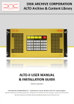
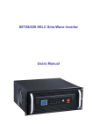
PowerPrem Series
Line Interactive Sine Wave UPS
This specification covers the requirements & quality assurance provisions for AC line powered
uninterruptible power supplies (UPS).
The UPS shall utilize line-interactive UPS topology in which the inverter works “in reverse” charging
the batteries during normal operation, providing greater efficiency, and reliability. The UPS consists of
an autotransformer, battery charger control circuit, battery, Bi-lateral inverter, transfer switches and all
associated controls, monitoring and major protection devices.
The UPS automatically maintains continuity of electrical power within tolerances and time frames
specified in this product specification.
1.2
Modes of Operation
In normal operation incoming AC power is fed directly to the output or via an autotransformer. In this
mode, power is also derived from the utility for the battery charger. The battery can be charged from the
utility irrespective of whether the UPS is ON or OFF.
In the event of utility abnormalities (sags and swells), the AC output power shall be corrected by means
of boost (sag correction) or buck (swell correction) compensation taps. Operation of the compensation
taps shall be seamless and automatically maintain the proper output voltage for the connected critical
equipment. The compensation taps shall be designed for indefinite operation at full rated load to their
voltage limits, without discharging the battery.
In the event of a utility outage, the output is transferred from the utility power to the inverter which
supports the load until the battery is discharged or the utility returns, whichever occurs first.
1.3 Built-in SNMP/web agent slot
PowerPrem 5000 Spec Sheet
PAGE 1 OF 8
With an optional SNMP agent card, the UPS can be connected to a network as a node. It can be
accessed and managed from a worldwide network via a single SNMP management console located
anywhere in the network. Users can monitor their UPS with a web browser. Users have secure access
to their web server UPS information from anywhere on the Internet or Intranet.
1.4
DIP switch setting
DIP 1
DIP 2
220V System
Down
Up
220V / 60Hz *
Up
Up
220V / 50Hz
Up
Down
230V / 50Hz
Down
Down
240V / 50Hz
DIP 3 for AC auto turn-on when city power returns
110V System
100V / 50Hz
110V / 60Hz
115V / 60Hz
120V / 60Hz
UP = Enable / Down = Disable
DIP 4 for Green Mode setting
UP = Enable / Down = Disable
1.5
1.5.1
INDICATION AND CONTROL
LCD description:
5.
1.
2
.
4.
16.
13.
AC out
V
AC in
Hr. to ON
BATT.
Min. to OFF
TEMP.
Hz
TIMER
℃
3.
14.
HIGH
6.
PowerPrem 5000 Spec Sheet
7.
8.
LOW
9.
10.
11.
12.
PAGE 2 OF 8
No. Symbol
Indication
Description
1.
Over load
The loading exceeds the rating of UPS.
2.
Load level
The higher the loading, the more bars will illuminate.
3.
UPS is loaded
When “Green Mode” is enabled, this symbol will display if the
loading is over 30W (approximately), and disappears when it is under
25W (approximately). Refer to User’s Manual 4.2.5. If “Green
Mode” is disabled, the symbol will always display.
4.
Normal or Inverter
mode
(1) The sine wave symbol will display steadily without battery
symbol when UPS is in the normal mode.
(2) The sine wave symbol and battery symbol will blink when the
UPS is in back-up (inverter) mode.
(3) The sine wave symbol will display steadily with blinking battery
symbol when the UPS is in testing mode.
5.
Buck mode
The AVR (Auto Voltage Regulator) is reducing the output voltage of
the UPS (when the input voltage is too high), and the sine wave
symbol, as mentioned in item 4, will also display steadily to indicate
that the output is in the normal mode.
6.
Boost mode
The AVR is increasing the output voltage of the UPS (when the input
voltage is too low), and the sine wave symbol, as mentioned in item
4, will display to indicate that the output is in the normal mode
7.
Timer is enabled
This symbol will show up in the following situations:
(1) A turn-on / turn-off schedule has been set using the monitoring
software. Refer to User’s Manual 5.6 and the “Readme” file or
“Help” function of the monitoring software.
(2) The Green Mode is enabled and the loading is under 25W
(approximately). The UPS will turn itself off automatically in 30
seconds. Refer to 4.2.5 of User’s Manual.
8.
9.
HIGH
Thermal alarm
The temperature inside the UPS is over 55℃. If the user does not
reduce the load, the temperature will continue to rise and the UPS will
shut down automatically at 60℃.
Fan is “ON”
This symbol is used only on long back-up (L) models.
The symbol will display whenever the cooling fan is running.
10.
Alarm off
PowerPrem 5000 Spec Sheet
The audible alarm has been silenced. To reset the alarm in Back-up
mode, push the control button (not available during low battery level
PAGE 3 OF 8
in Back-up mode).
11.
UPS fault
The UPS has failed and must be repaired. Contact a qualified service
person.
12.
Battery normal
(1) In normal operation, this symbol indicates a charged battery.
Battery low
(2) When the battery charge level is low, the word “LOW” will be
added to the symbol.
13.
Battery
replacement
The battery has failed and must be replaced. The battery is checked
each time the Test Function is executed.
14.
Battery voltage
level
(1) The higher the battery voltage, the more bars will illuminate.
Mode
Value
Description of Mode / Value
AC out
V
AC output voltage.
AC in
V
AC input voltage.
AC out
Hz
AC output frequency.
BATT.
V
DC battery voltage.
TEMP.
℃
UPS internal temperature.
TIMER
Min. to off
The UPS will turn off when the displayed value reaches zero. For
example, if the timer shows 0.5 Min to off, the UPS will shut down in
30 seconds.
TIMER
Hr. to on
The UPS will turn on when the displayed value reaches zero. For
example, if the timer shows 48.0 Hr to on, the UPS will turn on in 2
days.
BATT.
Min. to off
The estimated remaining run time in Back-up mode. The accuracy of
the value is influenced by the loading type, ambient temperature and
battery condition (old or new).
LOW
15.
1.5.2
(2) When the UPS is charging the battery, the battery symbol and the
level indicator will blink together.
Auto self-test Function:
In normal mode of UPS, turn on your computer and push the button on the front panel for
self-test. The UPS will simulate a power outage and transfer your load to the UPS’s battery.
If low battery warning sounds during the test, it means that the battery set is weak and
requires extended recharge. If battery NG warning sounds, it means that the battery set is
damaged and requires replacement.
PowerPrem 5000 Spec Sheet
PAGE 4 OF 8
1.5.3
Auto battery test function:
In normal mode of UPS, the UPS will test its battery connection and status every 20 minutes,
when battery is NG, open circuit or not well connected, the UPS will emit low battery alarm,
at the same time its LCD will show battery NG mark. The battery NG mark will not
disappear until the battery is well connected or replaced by good ones.
1. 6
COMMUNICATION INTERFACE:
The UPS provides both computer interfaces, smart software (RS-232) and dry contact
(DB-9); by using different software and cable, the UPS shows different monitoring
function.
1.6.1
The definition and setup for RS-232 is as following:
Baud Rate
: 2400 dps
Data Length : 8 bits
Stop Bit
: 1 bit
Parity
: None
5 4 3 2 1
9 8 7 6
1.6.2
Pin #6
: RS-232 data Tx out.
Pin #7
: Common of Pin #6 and Pin #9
Pin #9
: RS-232 data Rx In
The definition and setup for DB9 (optional) is as following:
Pin #2
: AC Power Failure
Pin #4
: Common GND of Pin #2 & Pin #5
Pin #5
: UPS Battery Low
Pin #6
: Turn off UPS
Pin #7
: GND of Pin6
The interface with computer is diagramed as above for your reference. Use Pin #4 as
the common of Pin #2 and Pin #5, Pin #2 and Pin #4 will become close loop from open
when the utility fails, Pin #5 and Pin #4 will become close loop from open when the
battery level is low.
If battery NG happen and is sensed by the UPS’s auto battery test function, Pin #5 and
Pin #4 will also become close loop.
The UPS will shut down itself when the high level from RS-232, sustained for 3
seconds, which is applied between Pin #6 and Pin #7.
PowerPrem 5000 Spec Sheet
PAGE 5 OF 8
2.0
2.1
Electrical Requirements
Input
Input Range when it is with 5% Output (Standard)
OVER HIGH VOLTAGE PROTECTION
( + ) 22% of rated voltage
HIGH VOLTAGE TRANSFER POINT 2
( + ) 15% of rated voltage
HIGH VOLTAGE TRANSFER POINT 1
( + ) 5% of rated voltage
LOW VOLTAGE TRANSFER POINT 1
( - ) 5% of rated voltage
LOW VOLTAGE TRANSFER POINT 2
( - ) 13% of rated voltage
TOO LOW VOLTAGE PROTECTION
( - ) 20% of rated voltage
AVR FUNCTION
Input Range when it is with 8% Output (Option upon request)
OVER HIGH VOLTAGE PROTECTION
( + ) 36% of rated voltage
HIGH VOLTAGE TRANSFER POINT 2
( + ) 25% of rated voltage
HIGH VOLTAGE TRANSFER POINT 1
( + ) 8% of rated voltage
LOW VOLTAGE TRANSFER POINT 1
( - ) 8% of rated voltage
LOW VOLTAGE TRANSFER POINT 2
( - ) 21% of rated voltage
TOO LOW VOLTAGE PROTECTION
( - ) 32% of rated voltage
AVR FUNCTION
2.1.1 Inrush current (initial start up)
Tested at 220 VAC RMS., 25 deg C: the UPS should not sink any inrush current from AC input when
initial start up.
2.1.2 Input line transient immunity
No component failures or malfunction should be found when the UPS is subjected to an input line
transient.
2.1.3
Surge Protection
Both the AC input and AC output should have surge protection with energy rating totally 800 joules.
By checking at the AC output of UPS, the surge protection should have zero clamping response time.
2.2
Output
Model
Power (VA) max.
PowerPrem 5000 Spec Sheet
PowerPrem 5000
5000VA
PAGE 6 OF 8
Power (Watts) max.
3500W
Output
Waveform
Nominal Voltage
Transfer Time
Pure Sine wave
220/230/240VAC by DIP switch setting
2.5 ms typical, 3.5ms maximum
Line Mode Voltage
Nom. Range (no load)
220/230/240VAC ±5%
Battery Mode Voltage Regulation
220/230/240VAC ±3%
Transient Response
(Battery mode with R type load)
0%, 100%, 0% ±15% max
50ms to stable
Peak Voltage
390V peak
Transient Recovery
Zero ~ 1ms
Output Frequency (battery mode)
50/60Hz ±0.1Hz
Output Voltage Distortion
R Load
< 4 % before pre-alarm
< 8 % after pre-alarm
SMPS Load
< 7 % before pre-alarm
< 15 % after pre-alarm
Efficiency
Line Mode
> 97 %
Boost/Buck Mode
> 93 %
Battery Mode(R load)
> 80 %
Short Circuit Protection
Line Mode
Battery Mode
PowerPrem 5000 Spec Sheet
Circuit protection
Current limit with fuse
PAGE 7 OF 8
2.2 Battery (all parameters are defined at 25 Deg. C)
PowerPrem 5000
Type / Rating
12V 7Ah 12PCS
Acceptable Manufacturers
BPC, Yuasa, CSB
Standard life (3 – 5 years)
Life
Back-up Time (at full load)
> 6 minutes typical
Protection
Battery Protection
Fuse
Low Batt. Alarm Level
63.6V ±3%
Low Batt. Shut Down Level
57.6V ±3%
82V
RECHARGER VOLTAGE
RECHARGER METHOD
RECHARGER CURRENT
RECHARGER
RECHARGER TIME
PROTECTION
ON/OFF Control with Constant Voltage and Current Limiting
6A maximum
10A maximum
2 hrs to 90%, 6hrs to 100%
Charging Voltage and Current Limited by control IC, Over charge
protected by CPU
PowerPrem 5000
Tower Dimensions
180mm W x 500mm D x 435mm H
Rackmount Dimensions
435mm W x 500mm D x 180mm H
Unit Weight
PowerPrem 5000 Spec Sheet
80Kgs (inc Batteries)
PAGE 8 OF 8