1
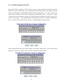
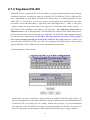
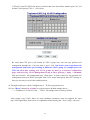
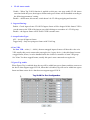
Power Over Ethernet 8-Port Gigabit Web Smart Switch User’s Manual Version: 3.9 May 15, 2008 1 TABLE OF CONTENT 1.0 INTRODUCTION ...........................................................................................................................................................3 1.1 MAIN FEATURES .........................................................................................................................................................3 1.2 START TO MANAGE THIS SWITCH................................................................................................................................5 1.2 START TO MANAGE THIS SWITCH................................................................................................................................5 2.0 WEB MANAGEMENT ....................................................................................................................................................6 2.1 CONFIGURATIONS........................................................................................................................................................7 2.1.1.1 SYSTEM INFORMATION ..........................................................................................................................................7 2.1.1.2 DHCP ...................................................................................................................................................................8 2.1.1.3 RELOCATE HTTP PORT NUMBER ............................................................................................................................8 2.1.1.4 TAG VLAN MANAGEMENT GROUP ( CPU PORT )...................................................................................................8 2.1.2 PORTS ......................................................................................................................................................................9 2.1.4 TAG-BASED VLAN ................................................................................................................................................11 2.1.5 PORT TRUNKING ....................................................................................................................................................14 2.1.7 QUALITY OF SERVICE .............................................................................................................................................16 2.1.8 STORM CONTROL ...................................................................................................................................................18 2.1.9 LACP ....................................................................................................................................................................18 2.1.10 RSTP ...................................................................................................................................................................20 2.1.11 IGMP...................................................................................................................................................................22 2.1.12 802.1X .................................................................................................................................................................23 2.1.13 POWER OVER ETHERNET .....................................................................................................................................25 2.2 MONITORING ............................................................................................................................................................26 2.2.1. PORT STATISTICS ...................................................................................................................................................26 2.2.2 LACP STATUS ........................................................................................................................................................27 2.2.3 RSTP STATUS .........................................................................................................................................................28 2.2.4 IGMP STATUS ........................................................................................................................................................28 2.2.5 PING .......................................................................................................................................................................29 2.3 MAINTENANCE..........................................................................................................................................................30 2.3.1 WARM REBOOT ......................................................................................................................................................30 2.3.2 FACTORY DEFAULT .................................................................................................................................................30 2.3.3 FIRMWARE UPDATE ................................................................................................................................................30 2.3.4 CONFIG FILE ..........................................................................................................................................................32 3.0 TERMINAL MODE MANAGEMENT ..............................................................................................................................32 4.0 LED & 7-SEGMENT LED DISPLAY.............................................................................................................................34 2 1.0 Introduction This web smart switch is a high speed switch that provides up to 8 10/100/1000Mbps copper Ethernet ports, besides, it provides many advanced function for nowadays variety of network application but at lower cost. User doesn’t have to learn many sophisticated management function which are usually shown in SNMP switch but just to learn some simple or common control or setting function through either out-of-band RS232 port or Ethernet port, however, some new, advanced and important function such as Tag-VLAN, Trunking, RSTP and IGMP are also supported same as SNMP switch, this means, user doesn’t have to pay high cost as tradition layer 2 SNMP switch while he still can get advanced or common function to meet requirement of advanced network application. This makes it very suitable for small or medium size company to build up simple network at beginning phase with lower cost. An optional long-ear accessory also makes it possible to operate in the rack mount environment. Non-blocking and maximum wire speed performance are designed on all switched ports, it not only supports auto-negotiation but also AUTO-MDIX function on all switched 8 10/100/1000M RJ-45 Gigabit copper ports no matter running with half or full duplex mode, these function make user easy to use and reduce the matching effort between straight and cross-over line issues. 8G web smart switch supports both port-based and 802.1Q (tag-based) VLAN to catch-up the application needed for coming VLAN age. To increase bandwidth application, it supports up to 4 trunk groups with maximum 8 ports on one Trunk, moreover, these trunk ports are with fair-over function to provide redundant back-up when one or some of trunk ports malfunction. Moreover, to reduced convergent time of STP protocol, Rapid STP ( RSTP ) is supported, to support multicast application IGMP is also supported. , Fully LED status display ease user’s installation and inspection, a reset button is also provided to make user easy to go back to default setting. 1.1 Main Features This switch provides the following main features: Non-blocking, full-line speed, store-and-forward Support jumbo frame, Max. packet length 9600 bytes Auto-Negotiation and Auto-MDIX on all 10/100/1000M copper ports Up to 8 10/100/1000 RJ-45 copper ports 144K byte packet buffer, 8K MAC entries Support port-based VLAN and tag-based (802.1Q) VLAN Support RSTP, IGMP, DHCP 3 Support “relocate port number” to “ http operation “ Port trunk with fail-over capability Support flow control for both full/half duplex operations Support Multicast storm, Broadcast Storm control as well as Flooding Control Support port mirroring Support Telnet and TFTP code upgrade LED display for each port to show link and activity status 7-segment LED display for each port to show power consumption and status 7-segment LED display for system to show total power consumption and status Desktop and optional Rack mountable kit Reset to default Field-code-upgrade through web browser 4 1.2 Start to Manage This Switch Either way user may start to manage this switch, web mode through Ethernet port or terminal mode through RS232 port. 1,2,1 Web mode default setting are: Default IP Address: 192.168.223.100 Default IP mask: 255.255.255.0 Default gateway: 192.168.223.254 Default Password: “ admin “ 1.2.2 Terminal mode default setting are: baud rate: 115,200, attribute: 8, None, 1, None Terminal mode operation: Default Password: “ admin “ Once terminal is connected, the basic operation rule are shown below Press “ ? “ to find root operation page, then choose command by typing little alphabets After enter command page, Press “ ? “ to find command parameters and format, further more, type “ command ? “ to get explanation. Type “ up “ or “ / “ to go back to previous page 5 2.0 Web management After login is successfully validated, the switch’s home page will show up. The left part on the page provides the function menus, while the right part provides the individual configuration value or system parameters value. Function manuals are divided into three categories, they are Configuration, Monitoring and Maintenance, all functions are shown briefly below 6 2.1 Configurations 2.1.1.1 System information The system diagram shows general common system information, they are H/W, F/W version, MAC address, IP address, subnet mask, IP gateway, default VLAN value of management port, name, password, timeout value, and SNMP communities…etc. Once user finish the setting, he must press the “ Apply “ button to execute all his setting, and whenever he needs, he may press the “ Refresh “ button to get updated status of system information. 7 2.1.1.2 DHCP The default DHCP is off, so Default IP or user defined IP is used when this machine is turning-ON, but if this switch needs an IP assigned from DHCP server, user may click the square field and then press “ Apply “ to get an IP which will be assigned by DCHP server “. User must be aware that if he enable DHCP from web page, and if the DHCP server is working, then after enable DHCP, he will lose contact of web page, because the IP address has been changed. At this moment, go through terminal mode and check configuration of IP, then get Dynamic IP to return web page. 2.1.1.3 relocate HTTP port number The default port number of HTTP command is 80, but unauthorized user may intrude this switch if he knows the IP of this switch, network manager may relocate this port number to other value, from 1024 to 65535, the same idea as above, once network manager change the value of HTTP’s port number, he will lost contact and he must regain web page by command modified as below: http://192.168.223.100:port_value 2.1.1.4 Tag VLAN management group ( CPU port ) At first time you turn on this device, all ports belong to default VLAN ID group (VID=1), so they can communicate to each other, and hence any port can be used as web management port to talk with CPU port inside, but, for example, assume user uses port 1 as web management port, then user create VLAN ID=10 on port 7,8 and create another VLAN ID = 20 on port 5,6, now 3 VLAN groups will be shown on VALN group table after he press “ Apply “ button. If VLAN 10 and VLAN ID 20 must be isolated, then user must delete member port 5,6,7,8 in default VLAN group( VID = 1 ). Be aware that CPU port is still remain on VID=1 group now, user can only perform web management through one of 4 ports, that is port 1,2,3,4, but if user want to perform web management from other port in existing different VLAN group, for example port 8 in VID =10, then after creating new VLAN groups, he must go to system configuration page, and select Tag VLAN Management Group to 10 by pressing “ Apply “ command, then move RJ-45 ( web management port ) from port 1 to port 8, then user can perform web management from new RJ-45 port again. But if user forget what group that CPU belongs to, there are two ways to solve this condition below. (1) Through console port, check configuration of IP if he gets password, or (2) Press “Reset” button few seconds, let system return to default settings, that is, ---- >> IP address=192.168.223.100; … VID=1, all settings return to factory default 8 2.1.2 Ports Port status page always shows current port status of all 8 ports. User can set link mode, enable or disable flow control and jumbo frame, however, be noticed that the jumbo frame is global setting, it can’t be set on individual port but on all ports at a time. A default diagram is shown below, Choose and click the ports you want to set, for example, choose port 1, and set port 1 Flow Control enable, then press “Apply”, after execution, diagram will shown below 9 2.1.3 Port-based VLAN Port-based VLAN is a kind of VLAN which is a group of ports marked as a kind by group ID, different VLAN ( different ID ) can’t communicate to each other. Before the setting, user must be aware of that there is a default Port-based VLAN, his group ID is 1, so, if user wants to set another new port-based VLAN, better set another group ID rather than 1. After press “ Apply “ button, the screen will show a updated VLAN Group table no matter user add a new group or delete a VALN group. The important thing is that port-based VLAN is valid only within same device, it will never be valid cross the devices. A default diagram is shown below. Choose and click the ports you want to group, for example, choose port 1, port 2 and set their group ID 2, then press “Apply”, after execution, diagram will shown below 10 2.1.4 Tag-based VLAN Tag-based VLAN is another kind of VLAN which is a group of ports marked as same kind by assigning a tag-value on each port, same as port-based VLAN, different VLAN ( different ID ) can’t communicate to each other, and before the setting, there is a default tag-based VLAN, which ID is 1 ( VLAN ID=1 ), so, if user wants to create another new tag-based VLAN, better set another VLAN ID rather than 1 ( tag-based VALN ID ranged from 1 ~ 4094 ). After press “ Apply “ button, the screen will show a new tag-based VLAN Group table, on the contrary, a tag-VLAN will be vanished if user delete a VLAN group. Two important things must be emphasized here, one is that tag-based VLAN members are valid not only within same device, but also cross the devices as long as they are with same VLAN ID; the other important thing is user must keep in mind that the VLAN ID of CPU port must be one of the VLAN group if user wants to manage through one of the ports of that VLAN group, otherwise, if there is no port with same VLAN ID as CPU port, the web management, in-band control, will be failed because different VLAN ( different ID ) can’t communicate to each other. A default diagram is shown below. At first time you turn on this device, all ports belong to default VLAN ID group (VID=1), so they can communicate to each other, and hence any port can be used as web management port to talk with CPU port inside, but, for example, assume user uses port 1 as web management port, then user create VLAN ID=10 on port 7,8 and create another VLAN ID = 20 on port 5,6, now 3 VLAN groups will be shown on VALN group table after he press “ Apply “ button. 11 If VLAN 10 and VLAN ID 20 must be isolated, then user must delete member port 5,6,7,8 in default VLAN group( VID = 1 ). See below Be aware that CPU port is still remain on VID=1 group now, user can only perform web management through one of 4 ports, that is port 1,2,3,4, but if user want to perform web management from other port existing in different VLAN group, for example port 8 in VID =10, then after creating new VLAN groups, he must go to System Configuration page, and select Tag VLAN Management Group to 10 by pressing “ Apply “ command, then move RJ-45 ( web management port ) from port 1 to port 8, then user can perform web management from new RJ-45 port again. But if user forget what group that CPU belongs to, there are two ways to solve this condition below. (1) Through console port, check Configuration of IP if he gets password, or (2) Press “Reset” button few seconds, let system return to default settings, that is, ---- >> IP address=192.168.223.100; … VID=1, all settings return to factory default After assign a tag VLAN, there are some attributes parameters must be assigned for some tag-VLAN application, here below are explanation when entering the “ Port Config “, they are: 12 1. VLAN Aware mode: Enable – When Tag-VALN function is applied on this port, user may enable VLAN Aware associated with this port, then ingress frames and egress frames will be handled according to the following parameters’ setting. Disable – default state, this means, switch doesn’t do VLAN tag stripping and insertion. 2. Ingress filtering: Enable - Check ingress frame VLAN ID. Ingress frame will be dropped if this frame's VID is not the same as the VID of the ingress port which belongs to a member of a VLAN group Disable – the Ingress frame will be flood if VID is not the same 3. Accept Packet Type: ALL - Accept all ingress frames Tagged only - Only accept ingress frames with VLAN tag 4. Port VID: Set Port VID = value ( 1 ~ 4096 ), then an untagged ingress frames will bear this value a its VID, usually this port is connected to un-tag device ( legacy device ), then this frame become a tagged frame, hence, it can be handled inside the switch as a member of same VID group. Set "None" for those tagged frames, usually this port is now connected to a tag-device 5. Egress Tag enable When Egress Tag is enabled, then, the tag will be added into egress frames and then sent out to the device that support tagged-VLAN, when this is disabled, tag will not be added into egress frame and then sent to device that does not support tagged-VALN. 13 2.1.5 Port Trunking A default diagram is shown below, and up to 4 groups are provided Choose and click the trunk ports you want to group, for example, choose port 1, port 2 into group 1, then press “Apply”, after execution, diagram will shown below 14 2.1.6 Port Mirroring A default diagram is shown below, Choose and click the ports you want to monitor, for example, choose port 2 is mirror port And the mirror source is port 5. then press “Apply”, after execution, diagram will shown below 15 2.1.7 Quality of Service There are 4 class priority can be set for each port: Low, Normal, Medium and High, because there are 8 priority levels ( 0 ~ 7 ) for each port, so 8 priorities map into 4 class must be done in this QoS control. There are 3 QoS Mode can be chosen: Port-based, 802.1P and DSCP. The frames sending not only per priority setting but also per Queue Mode setting. Strict Mode means highest priority setting gets first service to send frames, the lower priority frames must wait until all other higher priority frames are sent ( serviced ), then it gets service. WRR Mode means different priority are with different weighting to get service, that is, within a time period, the service times ( chance ) are a ratio among these 4 classes, user may choose one of preset setting from the manual. A default diagram with Strict Queue Mode is shown below Choose the port-based priority level for each port you want to set, then ports will get priority service as setting, for example, Under Strict Mode, Port 5,6,7,8 are set “ low ”, port 1,2,3,4 are set as high, medium, normal and low. Then, after “ Apply “, usually port 1 will get service at most of time and even all of the time. 16 When user choose the 802.1P priority, this means frames are with VLAN Tag inside the switch, the priority in the Tagged frame ( 2 bytes Tag in total ) must be set by application program. But 8 priority levels map into 4 class also must be done same as explained in previous paragraph. 17 2.1.8 Storm Control A default diagram is shown below, Choose and click type of storm you want to control, for example, choose Broadcast storm with 3,964 frames per second as upper limit, once the Broadcast frame rate higher than 3,964 frame per second, this port will be disabled. Press “Apply”, after execution, diagram will be shown below 2.1.9 LACP Different from the static port trunking, LACP provides another way to dynamically aggregate port to a group (trunk) according to IEEE 802.3ad. Once the protocol is enabled, the ports to be trunked by LACP will be executed automatically after press “ apply “ A default diagram is shown below, 18 Two parameters need to be set per port basis in this webpage: Protocol Enabled – to enable/disable LACP protocol for a port. Key Value – a number (1~255) to identify the LACP group for a port. All member ports in a LACP group have the same key values. Key number will be automatically generated if “auto” value is set Choose and click the trunk ports you want to group. For example, select port 5,6,7 and port 8 to group into a LACP group with key value “ auto “ for all ports, then press “ Apply” to activate the setting. The figure is shown below : 19 2.1.10 RSTP The Spanning-Tree Protocol (STP) is IEEE 802.1d standardized method for avoiding loops in switched networks. Enable STP to ensure that only one path at a time is active between any two nodes on the network. The Rapid-Spanning-Tree-Protocol (RSTP) is a more advanced protocol than STP according to IEEE 802.1w standard. RSTP can shorten spanning tree convergent time while network topology is changed. A default diagram is shown below, 20 Use the following parameters in the webpage to configure RSTP function: System Configuration ¾ System Priority – A value to identify the root bridge. The bridge with lowest value has the highest priority and is selected as the root. 16 numbers are provided in this field from 0 to 61140 in increments of 4096. ¾ Hello Time -- the number of seconds among the transmission of Spanning-Tree Protocol configuration messages. Enter a number 1 through 10. (default is 2) ¾ Max Age – the number of second bridge waits without receiving Spanning-Tree Protocol configuration messages before attempting a reconfiguration. Enter a number 6 through 40. (default is 20) ¾ Forward Delay -- the number of seconds a port waits before changing from its Spanning-Tree Protocol learning and listening states to the forwarding state. Enter a number 4 through 30. (default is 15) ¾ Force Version – normal: use RSTP; compatible: compatible with old STP protocol Port Configuration ¾ Aggregations – Enable/disable the RSTP protocol on aggregation links ¾ Protocol Enabled – Enable/disable the RSTP protocol per port basis ¾ Edge – Enable/disable to expect a port to be an edge port (an end station) or a link to another STP device ¾ Path Cost – A value on a port that switch uses to determine which port are the forwarding ports. The lowest number is forwarding ports. The value can be set from 1 to 200000000 or “auto” to be automatically generated. 21 2.1.11 IGMP The Internet Group Management Protocol (IGMP) is an internal protocol of the Internet Protocol (IP) suite. IGMP can manage the multicast traffic if the members (switches, router or other network devices) of group support IGMP. This switch provides IGMP snooping feature to detect IGMP queries, report packets and manage the IP multicast traffic through the switch. This feature can limit the forwarding multicast frames only to those ports that are a member of multicast group. Only IPv4 IGMP frames are recognized for this system. The following parameters are provided for configuring IGMP snooping for this system: IGMP Enabled – to globally enable/disable IGMP snooping function Router Ports – the port that is usually with source of multicast traffic stream Unregistered IPMC Flooding Enabled – to set forwarding option for unregistered (not joined) IP multicast traffic. Enabled: to flood frames to every port; Disable: to forward frames only to those IGMP member ports Two options can be set for each existing group: IGMP Snooping Enabled – to enable/disable snooping IGMP frames IGMP Querying Enabled – to enable/disable sending IGMP querying frames, in one Ethernet section, there is only one Querier, and Querier is usually in router device For example, video traffic comes from port 8 which is connected to a router, and port 3,4,5 are Connected to IGMP member, then the configuration may be set as below 22 2.1.12 802.1x A default diagram is shown below, user must contact the manager of RADIUS server, and then get IP, UDP port number ( usually fixed at 1812 ) and secret to operate 802.1X. Admin Mode: Auto: client will be authorized by authentication process Force Authorized: client will be authorized anyway Force Unauthorized: client won’t be authorized anyway Action: means execute command on single port or all ports when click Re-authenticate: authorized again on that port Force Reinitialize: force that port initialize Statistic: see statistic frames Parameters: Define time schedule on Reauthentication mode The default diagram as shown below: 23 24 2.1.13 Power Over Ethernet The diagram shown below is one PD device is loaded on port 1 while a management PC ( Non-PD ) is being connected to the port 8 of this POE switch. When there is PD device connected and loaded, this page will show real power consumption of each device on its connected port and the total balanced system power will be also shown at lower portion, moreover, if over current condition happens, it will show PD Error with red background color on that port status and shut-down the output power immediately on the port by disabling. Once this fault condition happen, fault condition must be removed before it function again, and remember, user must apply command “enable” to that port, then it can operate normally. . 25 2.2 Monitoring 2.2.1. Port Statistics Choose and click command manual, after execution, diagram will shown below, user can clear counter or refresh as will 26 2.2.2 LACP Status Choose and click command manual, after execution, diagram will shown like below, user can refresh as will 27 2.2.3 RSTP Status Choose and click command manual, after execution, diagram will shown like below, user can refresh as will 2.2.4 IGMP Status Choose and click IGMP status at command, after execution, diagram will be shown like below, user can refresh as will. There are IGMP v1, v2,v3 frames will be shown in the network, our switch only support IGMP V2, but it will handle some IGMP V3 frames. If this switch is Querier, it will show Querier state and Query frames it transmitted, if it is not Querier, it only show how many Querier frames it receives. Only one Querier in a network section, usually Querier is in router. 28 2.2.5 Ping Fill up the IP address you want to ping, set Time Out time and Counts, for example, IP = 192.168.223.25441, count = 5, time pout = 5 sec, then press “Apply”, then press “Refresh” after execution, diagram will shown below 29 2.3 Maintenance 2.3.1 Warm Reboot Choose and click command manual, diagram will shown like below, user can press Yes or No Warm Reboot Are you sure you want to perform a warm reboot? Yes No 2.3.2 Factory Default Choose and click command manual, diagram will shown like below, user can press Yes or No Factory Default Are you sure to reset configurations to factory default? Yes No 2.3.3 Firmware Update Choose and click command manual, diagram will be shown, and then direct the location of the file that is to be updated, then press “ upload “, if success, it will be shown below Software successfully loaded Do you want to activate new software? Yes No Press, “yes” then you get new code to execute, however, after activate the new code, then, 5 ~ 10 seconds later, press “reset button” at front panel so that the new default setting will be also updated, because different version of code is usually with different data structure of initial default setting 30 [Notes for Firmware Update] A Firmware version information will be shown at the system configuration page, before code update, user must know below F/W Version 2.7 or later, it will be designated suffix as “ T “ or “ L “ to distinguish this device is Ti solution or Linear solution. The Linear solution device may provide budget power display only while Ti solution device may provide real power consumption display. H/W version is shown at label on the rear panel.and Ti solution start from 3.0 For example, H/W: 2.0 -------------- >>> indicate the upper module is Linear solution inside H/W: 3.0 -------------- >>> indicate the upper module is Ti solution inside F/W: 2.7T ------------- >>>> suffix “T “indicates F/W is for Ti solution. F/W: 2.7L------------- >>>> suffix “T “indicates F/W is for Linear solution. F/W code between suffix T and suffix L ( Ti and Linear ) can not be cross updated. 31 2.3.4 Config File Choose and click command manual, diagram will be shown, and then direct the location of the file that is to be backup, give a name, then press “ Backup “ Configuration File Backup/Restore Configuration File Backup Backup Choose and click command manual, diagram will be shown, and then direct the location of the file that to be restored, then press “ Restore “ It will show transfer completed if it success. Configuration File Restore Restore 3.0 Terminal Mode management Terminal mode is easy to operate, it is useful when in-band ethernet communication is malfunction, or user is used to CLI interface operation, or he wants to know some parameter setting, for example, before in-band management through ethernet, user has to know the IP address, subnet mask, …etc, he may get this information by checking the configuration under IP command, he also may try to modify the IP address, CPU management group used in tag-VLAN configuration operation, or any other function through terminal mode. And most convenient, if user is used to configure the tag-VALN through terminal mode, he won’t be interfered by the CPU management group issue, CPU is always being connected with him while he is configuring the VLAN. User must set up the terminal parameters, such as Hyper terminal in Microsoft Window, Select COM #: COM 1, COM 2, …then, Set Baud rate to: 115,200, per second Set Attribute to 8, None, 1, None ( 8 bit, No parity, 1 stop bit, No protocol in hardware ) Once terminal is connected, enter the password, the basic operation are shown, and then when press “ ? “ the commands at top level will be shown as below 32 Key in “ Command “ and then key in “ ? “, second level will be shown , for example 33 If user wants to check the IP related information, he may do as below All other function can be operated likewise. Type “ up “ or “ / “ go back to previous page 4.0 LED & 7-segment LED display System LEDs: PWR LED: When AC input power and 3.3V DC are normal, this LED will turn ON DIAG LEDs: DIAG LED behave as heart-beat, it is blinking when system function is normal, and when it is OFF when the system is at abnormal state or during the reset transition. Port LEDs: Four LEDs per port; PoE status: upper two LED of each column. When upper “Green” LED is on, this indicates PoE switch is delivering power to PD device. When this LED is off, it indicates there is no power is delivering, or no PD device is loaded or PoE error happens. When “Orange“, is flashing, it indicates an overload condition is being detected, and will go steady when it confirms this over-current happens meanwhile, the system will shut-down PoE power delivering and turn Green LED off. The steady state Orange LED won’t go vanished unless the fault condition Is removed or reset by s/w command. 34 Ethernet status: lower two LED of each column. When upper “Green” LED is on, this indicates corresponding ethernet port linked at 100M bps, and it will blink when there is activity frame, when lower Orange LED is on, this indicates corresponding ethernet port linked at 1000M bps. 7-segment LEDs: 3 digits of 7-segment LEDs When mode switch is at normal position: 3 digits 7-segment LEDs always shows the total balanced power of whole system When there is no PD ( Powered Device ) load, the system is capable of delivering 120W to the load, that is, 15W per port maximum. The showing number will be reduced when load is added, and of course is added when load is removed, it always shows the total system balanced power. When mode switch is at indent position: 3 digits 7-segment LEDs always shows the real power consumption of port 1 at beginning with first 2 digits and shows load Class with last digit. And specially, it shows OFF when there is no load at port 1.. User may press another “click button “ which located left side of mode switch, then LED will be on and forward from port 1 to port 2 ….and so on if user click one by one. Then at this moment, 3 digits 7-segment LEDs shows the real power consumption of that port which LED indicates correspondingly. The end 35