1
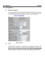
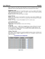
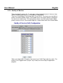
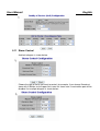
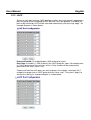
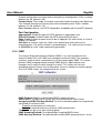
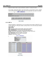
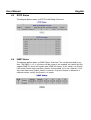
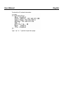
8 Port Gigabit Smart Switch
Manual
English
LINDY No. 25004
www.lindy.com
© LINDY ELECTRONICS LIMITED & LINDY-ELEKTRONIK GMBH - FIRST EDITION (July 2008)
User Manual
1.0
English
Introduction
Thank you for purchasing the LINDY 8 Port Gigabit Smart Switch with 2 shared mini GBIC ports.
This high-performance Layer 2 network switch is ideal for use in either the home or the office
All of its ports are capable of 10, 100 or 1000Mbps auto-negotiation, while the 10/100/1000Mbps
auto-sensing ability provides the easiest, most hassle-free way to migrate from a Fast Ethernet to a
Gigabit Ethernet network.
This switch delivers a dedicated 10/100/1000Mbps connection to every attached client with no
bandwidth congestion issues. It also supports an auto MDI/MDI-X function, which means that each
port can be used to connect to another switch or hub without the need for crossover cables!
Store-and-forward architecture is used by the switch to filter and forward data after each packet is
received and examined to be free of errors. All of the ports support full and half-duplex operation
which doubles the network bandwidth and allows the simultaneous transmission and reception of
frames without causing collisions.
The switch provides 9KB Jumbo frame support which can improve network performance by
allowing more data to be sent per transmitted frame.
2.0
•
•
•
•
•
•
•
•
•
•
•
•
•
•
•
•
•
3.0
Features
Non-blocking, full-line speed, store-and-forward architecture
Supports 9KB jumbo frame
Auto-Negotiation and Auto MDI-X on all 10/100/1000Mbps copper ports
Up to 8 10/100/1000 RJ-45 copper ports
2 x Mini GBIC slots for Gigabit Ethernet LC fibre modules (shared)
144K byte packet buffer, 8K MAC entries
Supports port-based VLAN and tag-based (802.1Q) VLAN
Supports RSTP, IGMP, DHCP, FTP, HTTP & UPN
Supports “relocate port number” to “http operation”
Port trunking with fail-over capability
Flow control for both full/half duplex operations
Multicast storm, Broadcast Storm control as well as Flooding Control
Port mirroring
Supports Telnet
LED display for each port to show link and activity status
Desktop and optional Rack mountable kit
Field-code-upgrade through web browser
Managing the switch
The switch can be managed through the RS232 port or in web mode through the Ethernet port.
3.1
Web mode default setting:
Default IP Address: 192.168.223.100
Default IP mask:
255.255.255.0
User Manual
English
Default gateway:
192.168.223.254
Default Password: “admin”
3.2
Terminal mode default setting:
Baud rate:
115,200
Attribute:
8, None, 1, None
Default Password: “admin”
Once the terminal has connected follow the instructions below:
Press “?” to find the root operation page, then choose the command you require by
typing in lower case
When you enter the command page, press “?” again to find the command parameters
and the format. For more information type “command ?” to get an explanation of the
command parameters
Type “u” or “/” to go back to previous page
4.0
Web Management
When your login has been successfully validated, the switch’s home page will appear. The left part
of the page provides the function menus and the right part provides the individual configuration or
system parameters values. The function manuals are divided into three categories, they are
Configuration, Monitoring and Maintenance, these are shown below:
User Manual
5.0
English
Configurations
5.1
System Information
The system configuration screen below shows the details and the status of the switch.
If any changes are made you must choose “Apply” for the changes to take effect.
Pressing the “Refresh” button will update the status of the system information
5.2
DHCP
By default DHCP is turned off, so a Default IP or user defined IP address is used
when the switch is turned on. If the switch needs an IP assigned from a DHCP server,
then tick the “DHCP Enabled” box and click on “Apply”. Note: if you are in web page
mode, connection to the switch will be lost. You will need to log back into the
system configuration using the new IP address provided by the DHCP Server.
User Manual
5.3
English
Relocate HTTP port number
The default port number of the HTTP command is 80, unauthorised users may
access the switch if they know the IP address. You may set the HTTP port number to
any other value, from 1024 to 65535. Note: once the HTTP port number has been
changed you will lose connection to the switch. To access the switch again use the
following address replacing it with the new port number
http://192.168.223.100:port_value
5.4
Tag VLAN management group (CPU port)
The default VLAN ID group will be VID=1 for all ports. This is to allow the ports to
communicate with each other and also allow you access to the Web Management via
any port when powering the switch on. The web management console can only be
accessed by ports on the VID=1 ID group. To access the Web management console
through other ID groups, go to the system configuration page and select Tag VLAN
Management group 10 and press apply. Now move the RJ-45 (web management
port) from port 1 to the port selected. If you do not know which port has been selected
to host the web management console you will need to “reset” the switch. This can be
done by pressing the reset button for a few seconds. The switch will then return to
default settings, IP Address 192.168.223.100 all ports VID=1
5.5
Port Configuration
The port status page shows the current status of all 8 ports. You can set the link
mode speed, enable or disable flow control and set the jumbo frame size. Note: the
Framesize for all ports can only be set to the same value. An example diagram is
shown below:
User Manual
English
Select the changes you want to apply: Eg. If you choose port 1 to have Flow Control
enabled, tick the box and then press “Apply”, the screen below will then appear upon
refresh. An example diagram is shown below:
5.6
Port-based VLAN
Port-based VLAN groups ports by group ID which mean ports on different VLANs
(different IDs) can’t communicate with each other. The default group ID is 1, before
setting another port-based VLAN you must set up a VLAN ID group. This new group
will appear in the Port-based VLAN configuration table. Note: Only member ports in
group ID 1 will be able to access other ports on the same group. An example
diagram is shown below:
User Manual
English
Choose and click the ports you want to group, for example, choose port 1, port 2 and
set their group ID 2, then press “Apply”. An example diagram is shown below:
5.7
Tag-based VLAN
Tag-based VLAN allows you to assign a tag-value for each port. The same as portbased VLAN, ports on different Tag-based VLANs (different IDs) can’t communicate
with each other. The default Tag-based VLAN ID is 1 (VLAN ID=1), another Tagbased VLAN can be created using numbers from 1 ~ 4094. Note: Tag-based VLAN
members are not only valid within the same device but can also cross devices
as long as they are the same VLAN ID. You can only manage the switch if one
of the VLAN groups are in the VLAN ID of the CPU port. An example diagram is
shown below:
User Manual
English
The default VLAN ID group for all ports is VID=1, this is to allow any port to be used
for web management communication with the CPU.
If you wish to isolate ports on a separate VLAN, then you must delete the ports from
VLAN=1 and create another VLAN ID. For example, below we have added ports 7 &
8 to VLAN ID=10 and ports 5 & 6 to VLAN ID=20.
After these changes, you can perform web management on any of the 4 ports on
VID=1. To perform web management on a port in another VLAN you must go to the
system configuration page and select Tag VLAN management group. Once you apply
the changes you must move the RJ-45 connection from port 1 to the port selected.
If you are not sure what port the CPU is active on then you can either:
1. Check for a password through the console port and the configuration of the IP
2. Reset the unit to factory default settings by holding in the reset button for five
seconds
User Manual
English
When assigning a tag VLAN, some parameters must be assigned for the tag VLAN
application, here are some definitions of titles when entering the “Port Config”:
VLAN Aware mode:
Enable: When you enable the Tag-VLAN function, you may enable VLAN Aware
mode associated with this port. Ingress and egress frames will be handled according
to the following parameters’ setting
Disable: By default VLAN Aware mode is disabled
Ingress filtering:
Enable: Check the ingress frame VLAN ID. The Ingress frame will be dropped if this
frame's VID is not the same as the VID of the ingress port which belongs to a member
of a VLAN group
Disable: The Ingress frame will be flooded if the VID is not the same
3. Accept Packet Type:
ALL: Accept all ingress frames
Tagged only: Only accept ingress frames with VLAN tag
4. Port VID:
Set Port VID = value (1 ~ 4096), then untagged ingress frames will bear this value as
its VID. Usually this port is connected to an un-tagged device (legacy device), then
this frame becomes a tagged frame. This will allow it to be handled inside the switch
as a member of same VID group
5. Egress Tag enable
When Egress Tag is enabled, the tag will be added into egress frames and then sent
out to the device that supports tagged-VLAN. When this is disabled, a tag will not be
added into egress.
User Manual
5.8
English
Port Trunking
The default diagram is shown below, and up to 4 groups are provided:
Choose and click the trunk ports you want to group, for example, choose port 1, port
2 into group 1, then press “Apply”. An example diagram is shown below:
5.9
Port Mirroring
Choose and click the ports you want to monitor, for example, mirror port 2 with port 5.
then press “Apply”. An example diagram is shown below:
User Manual
English
5.10 Quality of Service
There are 8 priority levels (0 – 7) each port can be mapped to one of 4 classes (Low,
Normal, Medium and High) this can be done in QoS control.
There are 3 QoS Modes: Port-based, 802.1P and DSCP. The frames are sent by the
priority and Queue Mode settings. Strict Mode means the highest priority setting gets
first service to send frames. The lower priority frames must wait until all other higher
priority frames are sent. An example diagram is shown below with Strict Queue Mode:
When you choose 802.1P priority, the frames have VLAN Tag inside the switch. The
priority in the Tagged frame (2 bytes Tag in total) must be set by the application
program.
User Manual
English
5.11 Storm Control
A default diagram is shown below,
Choose the type of storm you want to control, for example, if you choose Broadcast
storm with 3,964 fps as the upper limit, once this frame rate is reached the port will be
disabled. An example diagram is shown below:
User Manual
English
5.12 LACP
Similar to static port trunking, LACP provides another way to dynamically aggregate a
port to a group (trunk) according to IEEE 802.3ad. Once the protocol is enabled, the
ports to be trunked by LACP will be executed automatically after pressing “apply”. An
example diagram is shown below:
Protocol Enabled: To enable/disable LACP protocol for a port.
Key Value: A number (1~255) to identify the LACP group for a port. All member ports
in a LACP group have the same key values. A Key number will be automatically
generated if the “auto” value is set
Choose and click the trunk ports you want to group. For example, select port 5,6,7
and port 8 to group into an LACP group with key value “auto”. Then press “Apply” to
activate the setting. An example diagram is shown below:
User Manual
English
5.13 RSTP
The Spanning-Tree Protocol (STP) is the IEEE 802.1d standardised method for
avoiding loops in switched networks. Enable STP to ensure that only one path at a
time is active between any two nodes on the network.
The Rapid-Spanning-Tree-Protocol (RSTP) is a more advanced protocol than STP
according to the IEEE 802.1w standard. RSTP can shorten spanning tree convergent
time while network topology is changed. An example diagram is shown below:
System Configuration
System Priority: A value to identify the root bridge. The bridge with lowest value has
the highest priority and is selected as the root. 16 numbers are provided in this field
from 0 to 61140 in increments of 4096.
Hello Time: The number of seconds among the transmission of Spanning-Tree
Protocol configuration messages. Enter a number 1 through 10. (default is 2)
Max Age: The number of seconds the bridge waits without receiving Spanning-Tree
User Manual
English
Protocol configuration messages before attempting a reconfiguration. Enter a number
between 6 & 40. (default is 20)
Forward Delay: The number of seconds a port waits before changing from SpanningTree Protocol learning and listening state to the forwarding state. Enter a number
between 4 & 30. (default is 15)
Force Version: Normal: use RSTP/Compatible: compatible with the old STP protocol
Port Configuration
Aggregations: Enable/Disable the RSTP protocol on aggregation links
Protocol Enabled: Enable/Disable the RSTP protocol per port basis
Edge: Enable/Disable to expect a port to be an edge port (an end station) or a link to
another STP device
Path Cost: A value on a port the switch uses to determine which port are the
forwarding ports. The lowest number is forwarding ports. The value can be set from 1
to 200000000 or “auto” to be automatically generated
5.14 IGMP
The Internet Group Management Protocol (IGMP) is an internal protocol of the
Internet Protocol (IP) suite. IGMP can manage the multicast traffic if the members
(switches, router or other network devices) of the group support IGMP. This switch
provides IGMP snooping feature to detect IGMP queries, report packets and
manages the IP multicast traffic through the switch. This feature can limit the
forwarding multicast frames only to those ports that are a member of multicast group.
Only IPv4 IGMP frames are recognized for this system.
IGMP Enabled: Globally enable/disable IGMP snooping function
Router Ports: The port that is usually with source of multicast traffic stream
Unregistered IPMC Flooding Enabled: To set the forwarding option for unregistered
(not joined) IP multicast traffic.
Enabled: to flood frames to every port;
Disable: to forward frames only to those IGMP member ports
Two options can be set for each existing group:
IGMP Snooping Enabled: To enable/disable snooping IGMP frames
IGMP Querying Enabled: To enable/disable sending IGMP querying frames. In one
User Manual
English
Ethernet section, there is only one Querier, and this is usually the router
For example, video traffic comes from port 8 which is connected to a router, and port
3,4,5 are Connected to IGMP member, then the configuration may be set as below
5.15 802.1x
A default diagram is shown below, user must contact the manager of RADIUS server,
and then get the IP, UDP port number (usually fixed at 1812) and secret password to
operate 802.1X.
Admin Mode:
Auto: The client will be authorised by authentication process
Force Authorised: The client will be authorized anyway
Force Unauthorised: The client won’t be authorized anyway
Action: Execute the command on single port or all ports when click
Re-authenticate: Authorized again on that port
Force Reinitialize: Force the port initialization
Statistic: See statistic frames
User Manual
6.0
Monitoring
6.1
Port Statistics
The diagram below shows a statistical overview of all ports:
6.2
LACP Status
The diagram below shows an LACP Port Status Overview:
English
User Manual
6.3
English
RSTP Status
The diagram below shows an RSTP VLAN Bridge Overview:
6.4
IGMP Status
The diagram below shows an IGMP Status Overview: This can be refreshed at any
time. The IGMP v1, v2, & v3 frames will be shown in the network, the switch will only
support IGMP V2, but it will handle some IGMP V3 frames. If this switch is a Querier,
it will show Querier state and Query frames it transmitted, if it is not a Querier, it will
only show how many Querier frames it receives. Only one Querier is allowed in a
network section, usually the Querier is in router.
User Manual
6.5
English
Ping
Insert the IP address you want to ping, set the Time Out time and Counts. For
example, IP=192.168.1.141, count=5, time out=5 sec, then “Apply” and “refresh”. An
example diagram is shown below:
7.0
Maintenance
7.1
Warm Reboot
Select “yes” to perform a warm reboot
Warm Reboot
Are you sure you want to perform a warm reboot?
7.2
Yes
No
Yes
No
Factory Default
Select “yes” to perform a reset to factory default settings
Factory Default
Are you sure to reset configurations to factory default?
User Manual
7.3
English
Firmware Update
Once the firmware update has completed choose yes to activate your new software
version. An example diagram is shown below:
Software successfully loaded
Do you want to activate new software?
Yes
No
Once you select “yes” you will get a new code to execute. Ten seconds after
activating the new code press the “reset button” on the front panel so that the new
default setting will be also updated.
7.4
Config File
Select the backup command and choose a location to save the backup. Select a
name for your backup file and then click “backup”.
Configuration File Backup/Restore
Configuration File Backup
Backup
Select the restore command and select the location of the file to be restored. Select
“restore”, when the file has successfully restored you will get a message saying the
transfer was complete.
Configuration File Restore
Restore
8.0
Terminal Mode management
To use Terminal Mode Management you must set up the terminal parameters, such
as Hyper terminal in Microsoft Windows,
Select COM #: COM 1, COM 2, …then,
Set Baud rate to: 115,200, per second
Set Attribute to 8, None, 1, None (8 bit, No parity, 1 stop bit, No protocol in hardware)
Once the terminal is connected, enter the password, the basic operation are shown,
and then when press “?”, the commands at top level will be shown as follows:
User Manual
English
Key in “Command” and then key in “?”, second level will be shown, for example:
User Manual
To check the IP related information:
Type “up” or “/” go back to previous page
English
CE/FCC & WEEE Information
CE Certification
This equipment complies with the requirements relating to electromagnetic compatibility, EN55022/EN55024 class B for
IEC/EN61000-4-2/3 the essential protection requirement of Council Directive 89/336/EEC on the approximation of the laws of the
Member States relating to electromagnetic compatibility.
FCC Certification
This equipment has been tested and found to comply with the limits for a Class A digital device, pursuant to part 15 of the FCC
Rules. These limits are designed to provide reasonable protection against harmful interference in a residential installation.
This equipment generates, uses, and can radiate radio frequency energy and, if not installed and used in accordance with the
instructions, may cause harmful interference to radio communications. However, there is no guarantee that interference will not
occur in a particular installation. If this equipment does cause harmful interference to radio or television reception, which can be
determined by turning the equipment off and on, the user is encouraged to try to correct the interference by one or more of the
following measures:
•
Reorient or relocate the receiving antenna
•
Increase the separation between the equipment and receiver
•
Connect the equipment into an outlet on a circuit different from that to which the receiver is connected
•
Consult the dealer or an experienced technician for help
You are cautioned that changes or modification not expressly approved by the party responsible for compliance could void your
authority to operate the equipment.
This device complies with part 15 of the FCC Rules.
Operation is subject to the following two conditions:
1.
This device may not cause harmful interference, and
2.
This device must accept any interference received, including interference that may cause undesired operation.
WEEE (Waste of Electrical and Electronic Equipment),
Recycling of Electronic Products
United Kingdom
In 2006 the European Union introduced regulations (WEEE) for the collection and recycling of all waste electrical and electronic
equipment. It is no longer allowable to simply throw away electrical and electronic equipment. Instead, these products must enter the
recycling process.
Each individual EU member state has implemented the WEEE regulations into national law in slightly different ways. Please follow
your national law when you want to dispose of any electrical or electronic products. More details can be obtained from your national
WEEE recycling agency.
Germany
Die Europäische Union hat mit der WEEE Direktive umfassende Regelungen für die Verschrottung und das Recycling von Elektround Elektronikprodukten geschaffen. Diese wurden von der Bundesregierung im Elektro- und Elektronikgerätegesetz – ElektroG in
deutsches Recht umgesetzt. Dieses Gesetz verbietet vom 24.März 2006 an das Entsorgen von entsprechenden, auch alten,
Elektro- und Elektronikgeräten über die Hausmülltonne! Diese Geräte müssen den lokalen Sammelsystemen bzw. örtlichen
Sammelstellen zugeführt werden! Dort werden sie kostenlos entgegen genommen. Die Kosten für den weiteren Recyclingprozess
übernimmt die Gesamtheit der Gerätehersteller.
France
En 2006, l'union Européenne a introduit la nouvelle réglementation (DEEE) pour le recyclage de tout équipement électrique et
électronique.
Chaque Etat membre de l’ Union Européenne a mis en application la nouvelle réglementation DEEE de manières légèrement
différentes. Veuillez suivre le décret d’application correspondant à l’élimination des déchets électriques ou électroniques de votre
pays.
Italy
Nel 2006 l’unione europea ha introdotto regolamentazioni (WEEE) per la raccolta e il riciclo di apparecchi elettrici ed elettronici. Non
è più consentito semplicemente gettare queste apparecchiature, devono essere riciclate. Ogni stato membro dell’ EU ha tramutato le
direttive WEEE in leggi statali in varie misure. Fare riferimento alle leggi del proprio Stato quando si dispone di un apparecchio
elettrico o elettronico.
Per ulteriori dettagli fare riferimento alla direttiva WEEE sul riciclaggio del proprio Stato.
LINDY No. 25004
st
1 Edition July 2008
www.lindy.com