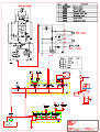
1
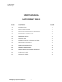
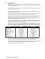
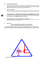
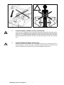
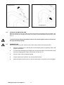
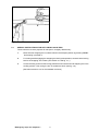
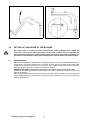
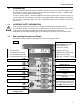
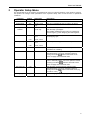
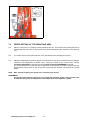
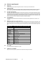
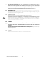
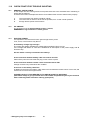
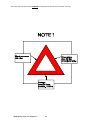
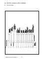
1804 ARC/S
OPERATORS HANDBOOK
1801-M1005
Tanco Autowrap Ltd.
Royal Oak Road
Bagenalstown
Co. Carlow
Ireland
Tel.: +353 (0)5997 21336
Fax: +353 (0)5997 21560
E-Mail: [email protected]
Internet: www.tanco.ie
11 March 2003
1804e20.wpd
USER'S MANUAL
AUTO WRAP 1804 S
CHAP.
CONTENTS
PAGE
1.0
INTRODUCTION
3
2.0
SAFETY PRECAUTIONS
4
3.0
SETTING UP / MOUNTING OF THE MACHINE
10
4.0
MOUNTING OF PLASTIC FILM
12
5.0
EMERGENCY STOP*
13
6.0
CONTROL BOX
14
7.0
SPEED SETTING OF THE WRAPPING ARM
18
8.0
ADJUSTING THE OVERLAP
19
9.0
OPERATION INSTRUCTION
20
10.0
PERIODIC MAINTENANCE
22
11.0
CHECK POINTS FOR TROUBLE SHOOTING
24
12.0
HYDRAULIC CHART
26
13.0
WARRANTY TERMS
28
* Emergency stop: see chapter 2.1
1
AUTO WRAP 1804 S
Bale wrapping machine
* Emergency stop: see chapter 2.1
2
1.0
INTRODUCTION.
TELLEFSDAL A.S congratulates you with the choice of AUTO WRAP bale wrapping machine. We
are certain you will be satisfied with the machine, and that you will have the pleasure of your
investment for many years.
AUTO WRAP 1804 S is hydraulically driven by its motor. The remote control unit is easy to use and
the functions are clearly marked.
The AUTO WRAP 1804 S is equipped with a patented, special mounting for the rollers, which enables
the machine to wrap square bales.
The AW 1804 S can wrap both square and rectangular bales, from 60 x 60 to 120 x 120 x 190 cm.
It can take bales of up to 1500 kg. It can also wrap round bales of up to ø1500 mm.
The AW 1804 S can be supplied as a TWIN model, i.e. the machine is equipped with two
prestretchers and two cutters. This gives the machines a significantly increased capacity.
The machine is developed and has been improved since the beginning in 1999, and is now a very
reliable and safe machine with high security built in.
This manual is meant to explain how AUTO WRAP 1804 S is prepared, mounted, used and how it
works, and along with the spare part's list be a reference for maintenance and troubleshooting. So
take good care of the book, it is a part of the machine.
Read carefully through this manual, and specially chapter 2.0, safety instructions, before starting
the machine, and follow the instructions thoroughly. If problems should occur, ask your dealer for
advice before you make the problem worse than it is. See also chapter 13.0, conditions of warranty.
AUTO WRAP
Height in working position
Width, min. / max.
Length, min. / max.
Weight
Wrapping arm speed, recom.
Wrapping arm speed, max.
Wheel size / max. air pressure
Bale size, max.
Bale weight, max.
Capacity
Prestretcher
Oil pressure / amount, min.
Electric connection
1804 S
1804 S TWIN
2960 mm
2440 / 3215 mm
2540 / 3425 mm
2460 kg
22 rev. per minute
27 rev. per minute
10,0/80-12BL 4,2bar
120x120x190
1500 kg
Approx. 40 bales per hour
750 mm
150 bar / 25 litres/minute
12 V DC
2960 mm
2440 / 3215 mm
2540 / 3425 mm
2560 kg
22 rev. per minute
27 rev. per minute
10,0/80-12BL 4,2bar
120x120x190
1500 kg
Approx. 40 bales per hour
750 mm
150 bar / 25 litres/minute
12 V DC
TELLEFSDAL A.S reserves the right to alter the product and/or its technical specifications without
prior notice, and without this entitling any alterations to previously supplied products.
© All rights in pursuance of the Copyright Act shall apply, and any reproduction of the contents of this
booklet, in whole or in part, is forbidden without the permission of TELLEFSDAL A.S.
Reservation is made for possible printing errors.
* Emergency stop: see chapter 2.1
3
2.0
SAFETY PRECAUTIONS.
TELLEFSDAL A.S does not take the responsibility for damages that may occur on machine,
persons or other equipment, because of the machine NOT being used as described in this
manual, or because of the safety precautions NOT being followed.
2.1
SAFETY EQUIPMENT.
Before using the machine, make sure that all guards and covers are securely fitted. The machine
must not be operated if a function does not work as described later in this manual. (See chapter 2.4).
The Auto Wrap 1804 S / TWIN models are equipped with an "EMERGENCY STOP" on the
wrapping arm. This device stops all functions instantly, but is by definition not an emergency
stop, because it does not interrupt the feed. Nevertheless it has an equivalent function, so we
have decided to call it an EMERGENCY STOP in this book.
2.2
BECOME FAMILIAR WITH THE OPERATIONS OF THE MACHINE.
If you are unsure how to operate the machine properly, either use of or maintenance to your Auto
Wrap, please contact your Auto Wrap dealer.
2.3
IMPORTANT!
MAKE ALWAYS SURE THAT NOBODY IS IN THE HAZARD
AREA OF THE WRAPPING ARM WHEN THE MACHINE IS IN USE.
THE MACHINE MUST NEVER BE OPERATED BY PERSONS WHOM DOES NOT KNOW ENOUGH
ABOUT HOW TO SAFELY OPERATE THE MACHINE, OR BY PERSONS UNDER 16 YEARS OF AGE.
* Emergency stop: see chapter 2.1
4
Fig. 2-2
2.5
DANGEROUS AREAS.
TELLEFSDAL A.S has given the safety to the operator the highest priority, but it is still impossible to
secure oneself of every danger area on the machine. Therefore we will now go through some of the
dangers that can occur when using the Auto Wrap balewrapper.
1.
PUNCH OF THE WRAPPING ARM.
During the wrapping process the arm rotates with a speed of 20-27 revolutions per minute
around the bale. On the arm there is mounted a prestretcher unit with a plastic roll. The
prestretchers speed can give a person serious injuries if one comes to close to the working
area of the wrapping arm. To reduce this danger we have mounted an emergency stop*
device on the wrapping arm, this stops all movement instantly when someone comes in the
way of it. It is very important that this protection always works and that it should not
under any circumstances be unconnected.
(See more about the emergency stop* in chapter 5.0).
2.
SQUEEZE-DANGER BETWEEN THE MAIN FRAME AND THE WRAPPING ARM.
As earlier explained, we have a wrapping arm with a prestretcher and a plastic roll. Once
every time around this wrapping arm passes the main frame. Here there may occur a
squeeze danger if a person stands to close to the main frame when the wrapping arm
passes. The distance between the main frame and the wrapping arm is not large enough to
give place for a person. Between the prestretcher and the bottom frame there can also be
a squeeze danger.
3.
SQUEEZE-DANGER BETWEEN THE STATIONARY AND THE WRAPPING ARM.
During the main wrapping process the wrapping arm moves around a stationary arm. Every
time the wrapping arm passes the stationary arm, there is a squeeze danger that can be
dangerous for the fingers. The distance between the stationary and the wrapping arm is
between 25-40 mm. (See fig. 2-2).
* Emergency stop: see chapter 2.1
5
Fig. 2-3
4.
SQUEEZE DANGER BETWEEN THE ROLLERS AND THE MAIN FRAME.
When adjusting the width of the rollers there is a danger of being squeezed. Keep away from
this area, fingers and feet also. (See fig. 2-3).
* Emergency stop: see chapter 2.1
6
Fig. 2-5
Fig. 2-6
5.
SQUEEZE DANGER CAUSED BY PLASTIC AUTOMATION.
At the end of the wrapping process the plastic shall be perforated and held tight until the
start of the next wrapping process. When the cutter arm moves down to lock the plastic,
there can occur a squeeze danger between the cutter arm and the cutter holder. The cutter
blade that perforates the plastic is very sharp, so keep hands away from the cutter. (See fig.
2-5).
6.
SQUEEZE DANGER BETWEEN THE ROLLERS.
When the rollers on the machine are moved together, there is not enough space for a
person between the rollers. Here there is a danger of being squeezed, so make sure that
nobody is between the rollers when they are moved together. (See fig. 2-6).
* Emergency stop: see chapter 2.1
7
Locking bolt off
Locking bolt on
Fig.2-7a
2.5
Fig. 2-7b
LOCKING THE WRAPPING ARM.
When the machine is not in use, make sure the locking bolt for the wrapping arm is mounted. If the
bolt is not mounted, the wrapping arm and/or the machine could be damaged during transport. (See
fig. 2-7).
Connecting heavy working implements often has an overall negative effect on the tractor's
driving and braking capacity.
2.6
TRANSPORTING.
When transported on a public road there are certain safety measures that must be taken:
1.
Move the wrapping arm in under the davit in the transport position by pressing "STOP" and
keeping it pressed in.
2.
For locking and disengaging the wrapping arm during transportation, ensure that the locking
bolt for the wrapping arm is fitted. (See section 2.5 and fig. 2-7.)
3.
Move the main rollers completely together.
4.
Always transport the machine in the lowest possible position.
5.
Make sure that the machine dos not cover the tractors lights. If necessary, mount extra lights.
* Emergency stop: see chapter 2.1
8
Fig. 2-8
2.7
SPECIAL INSTRUCTIONS FOR AUTO WRAP 1804 S TWIN
These machines must be prepared for transport in a slightly different way:
1.
Move the main wrapping arm in under the davit in the transport position by pressing "STOP"
and keeping it pressed in.
2.
For locking and disengaging the wrapping arm during transportation, ensure that the locking
bolt for the wrapping arm is fitted. (See section 2.5 and fig. 2-7.)
3.
Loosen the fixing screws for the locking plate which secures the second wrapping arm in the
working position. Then swing the arm in towards the davit. (See fig. 2.8.)
(See also sections 3 to 5 for the standard machines)
* Emergency stop: see chapter 2.1
9
Fig. 3-1
3.0
Fig. 3-2
SETTING UP / MOUNTING OF THE MACHINE.
Be careful! There is a danger of being crushed when working implements are fitted and
connected. Carry out the fitting procedures slowly and carefully, and use separate and
approved lifting equipment to make the work easier. See section 2 on safety regulations and
pay attention to the various safety decals displayed on different parts of the bale wrapper.
3.1
HINGED TOWER.
Because of the freighting of the machine, AUTO WRAP 1804 S is sometimes delivered with the tower
hinged down. The bracing clamps have to be fitted on each side of the davit. Fit the lower fixing
screws for the clamps (8 screws size 12 x 140). Inn some cases it may be necessary to adjust the
tower so that the tower and the rollers are right angel parallel.
SCREW IN SECURELY and after several hours' use, tighten all the screws once again.
Before use, the tower must be lifted up and fastened with 5 pcs. 16mm bolts. (Figure 4-1 shows the
machine at delivery).
Remove all packing strips and lift up the tower. Use a crane or the front-loader on the tractor and lift
in the liftingpoint at the top of the machine. (See arrow).Then mount the 5 pcs. M16 x 55 bolts with
washers and lock nuts.
* Emergency stop: see chapter 2.1
10
Fig. 3-4
Fig. 3-5
3.2
MOUNTING OF PRESTRETCHER.
It is to be fastened with the same 2 bolts that the locking bracket is fastened with. (You don't have to
remove the locking bracket). Remove the nuts and mount the prestretcher and the wrapping arm.
3.3
MOUNTING OF EMERGENCY STOP* ARM.
The machine is equipped with emergency stop-arms on each of the prestretchers.
The releasing arm for the emergency stop component must be mounted.
Put the arm into the bracket and mount the hinge bolt. Replace the washers and tighten the locking
nuts. (See fig. 3-5).
The return spring is to be fastened between the eye bolt on the arm and the eye bolt on the bracket.
* Emergency stop: see chapter 2.1
11
Fig. 4-1
Fig. 4-2
4.0
MOUNTING OF PLASTIC FILM.
4.1
When the plastic roll shall be mounted, you have to hold the prestretcher-rollers aside, Hold the rollers
aside and put on the holding hook. (See fig. 4-1).
4.2
Place a reel of film on to the prestretcher's holding axle and put on the springloaded lock. On delivery
the prestretcher is set for the 750mm film, the top bracket may be moved down enabling the use of
the 500mm film. (See fig. 4-3).
4.3
Pull the film between the rollers on the prestretcher in the direction of the arrow. (See fig. 4-2).
(See also the sign on the wrapping arm).
4.4
The filmholder / cutter is opened, pull out the film and place it over the U-shaped slot.
4.5
The cutter is closed, and the film will be held in place.
Fig. 4-3
* Emergency stop: see chapter 2.1
12
Fig. 5-1
Fig. 5-2
5.0
EMERGENCY STOP.
5.1
The machine is equipped with a safety guard on the wrapping arm, and its operation must be tested
before work itself is started.
5.2
The safety guard is designed to stop the wrapping arm injuring operators or objects, when starting
up or during the wrapping process.
5.3
The emergency stop* is constructed with a "positive" connection, i.e. it has to be in full order before
the machine can be started.
5.4
This consists of a release guard which is connected by a wire to the lever arm, and this activates a
small electrical switch via a sliding contact (14, fig. 5-2).
If the electrical circuit is broken, the hydraulic oil flow is cut off and all functions stop immediately.
This is indicated on the control box display by three illuminated dots.
5.5
Before use, this function must be tested. Start the wrapping arm, hold out an arm or any obstacle, the
wrapping arm stops before hitting.
5.6
To restart the machine the obstacle must be removed and the safety guard must return to its original
position. If "STOP" is pressed before "START", the wrapping continues from the point in the program
at which the emergency stop was activated. If, on the other hand, "STOP" is pressed before "ZERO",
then the wrapping sequence starts from the beginning again.
(See more in section 7.)
* Emergency stop: see chapter 2.1
13
TANCO AUTOWRAP
Electromagnetic Compatibility (EMC)
This product complies with Council Directive 89/336/EEC when installed and used in accordance with the relevant
instructions.
Our policy is one of continuous improvement and the information in this document is subject to change without notice.
Check that the software reference matches that displayed by the instrument.
© Copyright RDS Technology LTD 2003
\UK391-A.DOC
Service and Technical Support
PLEASE CONTACT YOUR NEAREST TANCO DEALER OR TANCO
Tanco Autowrap Ltd
Bagenalstown
Co. Carlow
Ireland
Tel:
+353 (0)503 21336
Fax:
+353 (0)503 21737
e-mail: [email protected]
www.tanco.ie
web:
Contents
1.
INTRODUCTION_______________________________________________________ 3
1.1
1.2
IMPORTANT SAFETY INFORMATION! ........................................................................................... 3
Main operating Functions and Display........................................................................................... 3
2
OPERATION __________________________________________________________ 4
2.1
2.2
2.3
2.4
2.5
2.6
2.7
2.8
Operation in Automatic mode ......................................................................................................... 4
Manually interrupting an automatic wrapping cycle ..................................................................... 4
Manual options in Automatic mode................................................................................................ 4
Operation in Manual mode.............................................................................................................. 4
The Display Menu ............................................................................................................................ 5
Selecting a Store Total .................................................................................................................... 6
Resetting a Store Total to Zero ....................................................................................................... 6
Setting the Number of Wraps.......................................................................................................... 6
3
OPERATOR SETUP MENU______________________________________________ 7
2
TANCO AUTOWRAP
1.
Introduction
The Tanco Autowrap Bale Wrap Controller enables the operator to monitor and control the operation of the
bale wrapper at any stage of the wrapping cycle. The controller is designed for models : 1300EH, 1510EH,
1510T, 1514S, and 1514T rotating-arm type wrappers.
There are 2 operating modes – Automatic and Manual. The automatic mode permits ‘one-touch wrapping’ to
ease the workload on the operator. The controller is fully programmable to optimise wrapping performance.
Bale counts are automatically logged in any one of 10 selectable memory stores, in addition to a grand total
memory store.
1.1
IMPORTANT SAFETY INFORMATION!
•
Please read and understand the instructions for using this controller before operating the machine.
• This controller is fitted with a pushbutton type On/Off Emergency Stop switch. Always ensure the controller is
switched OFF via this switch before attempting any adjustment or maintenance to the machine.
• Please follow ALL other safety instructions given in the manufacturers’ Operator Handbook for this machine.
1.2
Main operating Functions and Display
The principal instrument features and operating functions are shown in figure 1 below.
Figure 1
4-way Menu switch to
• Set No. of wraps
• Change/reset bale sub-total
• Access Operator Setup menu
• Access Technician Setup menu
A 2-line, 32 character dot matrix
, back-lit display shows in the
normal operating mode:
• Current No. of wraps
• Target No. of wraps
• Wrapping speed (rpm)
• Bale total (10 separate stores)
• Grand Total No. of bales
• Mode (‘M’ – manual, ‘A’ – Auto)
Add 1 wrap to current (or next) bale
Pause wrapping
Cut and grip film
Release film grip
Slow wrap
Fast wrap / Resume wrap after
manually pausing
Reverse wrap arm
Select Operating Mode
Bale unload
Index Bale (outside auto-wrap
cycle)
Pause bale rotation (during autowrap cycle)Start Automatic cycle
(Press STOP switch to stop cycle
e.g. in an emergency, otherwise
press
to pause the cycle)
Bale load
Power On/Off
/Emergency Stop
3
TANCO AUTOWRAP
2
Operation
2.1
Operation in Automatic mode
The controller is generally used in automatic mode for ‘one touch wrapping’.
1.
‘A’ on the display indicates that the controller is set in Automatic mode. If not, press
to select.
2.
With the rollers in the open position (step 4), bring the machine up to the bale.
2.
Press the
3.
Press the
switch to commence the automatic wrapping cycle. The cycle is completed when the target
number of wraps has been reached.
4.
Press the
switch* to move the rollers to the closed position.
switch* to move the rollers to the open position to unload the bale.
* The controller must be configured in the Operator Setup menu (section 3) so that this is a ‘one touch’ function
in automatic mode. Otherwise you must hold the switch for the required duration (as remains the case in
manual mode).
2.2
Manually interrupting an automatic wrapping cycle
Press the
switch to bring the wrapper to a controlled stop. Pressing the
switch will continue the
auto-wrap cycle from where it stopped.
For safety reasons, if it is necessary to work on the machine (e.g. in the event of a film break or the film
running out), then it is strongly recommended that you then switch the controller off via the red stop button
and disengage the machine power source. Pressing the
switch after switching the controller back on
will resume the auto-wrap cycle from where it stopped.
Unless it is an emergency situation, do not bring the machine to a stop by pressing the red stop button as this
will impose unnecessary strain on the machine.
2.3
Manual options in Automatic mode
With the controller in automatic mode, the following manual functions are possible.
SLOW WRAP (not during the wrapping sequence). Press
to resume the normal fast wrap.
REVERSE WRAP ARM (only enabled outside of the wrapping sequence). Press this button to nudge the wrap
arm backwards to the desired position.
PAUSE BALE ROTATION (function active during auto-wrap cycle). Hold this button to add more film to a
particular part of the bale. Release the button when sufficient additional film has been applied.
BALE INDEXING (function active outside auto-wrap cycle). Press and hold this button to index the bale.
Release the button when the bale is at the desired position.
NOTE: The controller can be configured from the ‘Operator Setup’ menu (section 3) so that this is a ‘one-touch’
function and the bale will then index for the preset period (e.g. to allow a ¼ turn).
ADD 1 WRAP Each time you press this button an additional wrap will be put on the current bale if the
wrapping sequence is in progress, or onto the next bale if the automatic cycle has not yet been started. You
can add as many wraps as required.
2.4
Operation in Manual mode
‘M’ on the display indicates that the controller is set in manual mode. If not, press
to select.
In manual mode you have total control of every stage of the wrapping cycle.
The software logic determines which manual functions can be activated at any point in the wrapping cycle.
Should the operator incorrectly select a function at a certain stage during the wrapping cycle, then that
operation will not be performed.
4
TANCO AUTOWRAP
2.5
The Display Menu
The Display menu is divided into 3 sections. At the top level are the settings used during the daily work with
the machine – i.e. Store totals and No. of Wraps.
The Operator Setup’ section enables the operator to perform adjustments to the machine operation – e.g. time
duration and time delay settings during the automatic cycle.
The ‘Technician Setup’ menu is not normally accessible to the operator without a PIN access code.
‘Technician Setup’ is not covered by this manual.
Use the 4-way switch to navigate the menu. Each menu screen indicates which keys to press to make the
settings. The instrument will default back to the main operating display after 30 seconds if no other key is
pressed
Here is a summary of the display menu;
Default display
Function
1300EH
1510EH
1514S
1510T
1514T
Range
Res.
Contrast
6
6
6
6
6
0-12
1
Sequence
1300
1510
1514
1510T
1514T
Film Break
OFF
OFF
OFF
OFF
Double Drive
OFF
Stop Bale Rotation*
No
OFF
ON/OFF
OFF
ON/OFF
No
No
Yes/No
Delay before slow at
end
1.0
1.0
1.0
0.4
0.4
0-9.9
0.1
Delay to stop after last
pulse
1.0
1.0
1.0
0.9
0.9
0-9.9
0.1
Rotation after
Wrapping
0.0
0.0
0.0
0.0
0.0
0-9.9
0.1
Manual Rollers In Hold
On Duration
0.0
0.0
0.0
0.0
0.0
0-9.9
0.1
Manual Rollers Out
Hold On Duration
0.0
0.0
0.0
0.0
0.0
0-9.9
0.1
Manual Index Bale
Hold On Duration
0.0
0.0
0.0
0.0
0.0
0-9.9
0.1
Language
English
English
English
English
English
E/F/D/NL/
DK
NOTE: There are additional sequences selectable in the Operator Setup menu but not shown in the table. These
sequences are for wrapper models to which this manual does not apply.
Please refer to section 3 for further explanation of the Operator Setup functions given in the table above.
5
TANCO AUTOWRAP
2.6
Selecting a Store Total
There are 10 individual memory registers labelled ‘Store A’ to ‘Store J’ for bale totals. Each time a bale cycle is
completed, the currently selected store total and the grand total increments by 1.
The currently selected store is displayed on one of the two screens selectable in the normal operating mode.
The default setting is Store A. To select a particular store, navigate the display menu using the 4-way switch.
Press the up/down arrow keys to select the store, then press the ENTER key to confirm the selection.
2.7
Resetting a Store Total to Zero
Stores A to J can be individually reset to zero at any time. The Grand Total store cannot be reset. First select
the store to be zeroed, then navigate the display menu as shown below.
Press the ENTER key to reset.
2.8
Setting the Number of Wraps
The default number of wraps is 16. You can set the target number from 0 to 99 by navigating the display menu
as shown below.
6
TANCO AUTOWRAP
3
Operator Setup Menu
The default settings for the machine are developed by Tanco for optimal operation of the machine. However,
the operator can change certain parameters in the ‘Operator Setup’ menu to take account of operational
conditions.
Parameter
Default
Application
Description
‘Film Break’
OFF
N/A
N/A
‘Double Drive’
OFF
1514S, 1514T
only
Set ‘ON’ to enable both pairs of rollers to be driven.
‘Stop Bale
Rotation’
No
1510S, 1514S,
1514T only
Set ‘Yes’ to delay bale rotation for a preset time period
after the wrap cycle begins.
This enables additional wraps of film to be applied for
extra strength e.g. when wrapping two bales together.
‘Delay to Slow’
1.0s
1300EH, 1510S,
1514
0.4s
1510T, 1514T
1.0s
1300EH, 1510S,
1514
0.9s
1510T, 1514T
‘Rotation After’
0.0s
All
Set time period to rotate the bale to an optimal
orientation for unloading
‘IN Hold Time’
0.0s
All
Sets the latch-on time period for closing the bale rollers.
Effectively allows ‘one touch’ operation instead of
having to hold the
switch in Automatic mode.
‘Delay to Stop
Determines the point of speed reduction at the end of
the wrapping cycle
Set to adjust the Stop position of the wrap arm
Does not apply when in Manual mode
‘OUT Hold Time’
0.0s
All
Sets the latch-on time period for opening the bale
rollers. Effectively allows ‘one touch’ operation instead
of having to hold the
switch in Automatic mode.
Does not apply when in Manual mode
‘Bale Hold ON’
0.0s
All
Sets the latch on time period for indexing a bale.
Effectively allows ‘one touch’ operation instead of
having to hold the
switch in Automatic mode (e.g.
to index a ¼ turn).
Language
English
All
Sets the language for the display prompts.
7
Fig. 7-1
7.0
SPEED-SETTING OF THE WRAPPING ARM.
7.1
Start the motor, let it run at approx. 2400 revolutions per min. The oil flow to the packing machine is
adjusted with the use of two control valves which are situated behind the machines "neck".[see fig.
7-1]
7.2
The control valve on the right-hand side, is for adjustment of the wrapping arm speed.
7.3
Adjust the wrapping arm speed to approx. 22 revolutions per minute. (Just below three seconds per
revolution.) The adjustment is carried out by turning the wheel on the control valve. Turning
clockwise REDUCES the speed and turning counterclockwise INCREASES the speed.
It is recommended not to wrap with higher speed than 22 revolutions per minute, because then the
plastic film will "catch" more air, this air can then not escape from the bale. The result is poor quality
fodder.
OBS!
Max. allowed wrapping arm speed is 27 revolutions per minute.
REMEMBER!
Increased speed of tractor engine do not increase the wrapping speed, it only increases the
oil flow into the system and by that also the temperature in the hydraulic system.
* Emergency stop: see chapter 2.1
18
Fig. 8-1
Fig. 8-2
8.0
ADJUSTING THE OVERLAP.
8.1
WRAPPING ARM SPEED.
Load a bale on to the machine. To be able to adjust correct overlap, check that the wrapping arm has
a speed of approx. 22 revolutions per minute. If not, adjust this by turning the control valve for
wrapping arm speed. (See chapter 7.3). When the wrapping arm speed is OK, you can set the
overlap.
8.2
OVERLAPPING.
Use a black marker to mark a line on the middle of the film wrapped on the bale. Adjust the control
valve for roller speed, (see fig. 8-1), so that the marker line is just covered. Approx. 52-53% is the
ideal overlap. (See fig. 8-2).
This adjustment can be kept as long as you wrap bales with approx. same diameter. When changing
bale size, control the overlap.
* Emergency stop: see chapter 2.1
19
Fig. 9-1
9.0
OPERATION INSTRUCTION.
We shall now go through a complete wrapping process, from loading to storage place, and explain
the practical use of Auto Wrap 1804 S.
9.1
WRAPPING SQUARE BALES.
a)
Minimum recommended bale size is 60 x 60 cm. If you wish, you can place two bales on top
of each other, and wrap them together as a bale of 120 x 90 cm. (Max. bale size is 120 x 120
cm).
b)
When wrapping rectangular bales, (e.g. 70 x 120 cm), the bale will rotate with uneven speed.
To get a smoother wrapping, or if you want more film on the long sides of the bale, it is
possible to mount an extra hydraulic valve that stops the rotation of the bale while the
wrapping arm continues to go.
c)
Sometimes it can be necessary to move the width between the rollers while wrapping. This
is most common when wrapping bad shaped and loosely pressed bales. If the machine has
problems rotating the bale, you can move the rollers in or out with the ROLLER OUT or
ROLLER INN with the control box while wrapping. Suggested roller width adjustment, (se
fig. 9-1).
9.2
START.
Remember that the plastic film end has to be locked in the U-shaped slot before starting the wrapping.
When the plastic film end is in the slot, push “AUTO”, and the wrapping arm now moves at ½ speed
for approx. one half revolution before it automatically switches to full speed. This is to avoid damage
of the film when starting. When the wrapping arm has done a couple of revolutions, the cutter-arm
automatically releases the film end. (See also chapter 6).
9.3
OVERLAP.
Control that the overlap is correct. If not, see chapter 8.0.
9.4
HOW MANY LAYERS OF PLASTIC FILM?
When the bale is completely covered with film, read the counter that displays the number of
revolutions done by the wrapping arm. This number has to be multiplied by 2 or 3, depending on how
many layers of film you want to have.
* 4 layers - multiply by 2.
* 6 layers - multiply by 3.
As long as you wrap bales with the same diameter, you can stop at the same number every time.
* Emergency stop: see chapter 2.1
20
9.5
STOP.
When the required number of revolutions is obtained, push the “AUTO”-button. The wrapping arm
will now rotate 1-2 revolutions, the cutter moves up, the arm speed is reduced and it stops at the right
place for next wrapping cycles. Then the cutter closes automatically, and the film is held tight in the
U-formed slot and perforated. The bale is now completely wrapped and will automatically off loaded
with the function rotation of bales. (Se more in chap.6.0)
* Emergency stop: see chapter 2.1
21
10.0
PERIODIC MAINTENANCE.
10.1
BEARINGS.
All ball-bearings are packed with grease, and do not need any more maintenance.
10.2
PRESTRETCHER.
If the machine is in daily use, the guiding sleeves at the prestretcher should be oiled once a week or
when needed. Sprockets and bearings on the prestretcher should also be oiled when needed.
10.3
CUTTER / FILM HOLDER.
The cutter / film holder is preadjusted from the factory and does not need further adjustments. When
replacing spares it may be necessary to re-adjust. The springs for the U-shaped slot must be adjusted
so that they are almost completely squeezed together when the cutter-arm is all the way down. If the
cutter arm must be adjusted take care so that the arm meets in the middle of the u-shaped slot and
that the cutter arm does not squeeze the springs completely together.
10.4
LINK BEARINGS.
The link bearings between the main frame and roller arms must be greased once a week or, as,
required.
10.5
GEAR OIL. (Applies only to TWIN machines.)
The oil in the gears of the wrapping motor must be changed after the first 100 hours of operation, and
then every 2,000 hours or at least once a year. Fill up with new oil, the quantity being about 0.25
litres. Use EP gear oil in the viscosity group VG 150 (ISO 3448) or similar. See the table of approved
oils.
TYPE OF OIL
+5° C / +40° C IV 95 min. (VG 150, ISO 3448)
AGIP
Blasia 150
ARAL
Degol BG 150
BP MACH
GR XP 150
CASTROL
Alpha SP 150
CHEVRON
Non leaded gear compound 150
ELF
Reductelf SP 150
ESSO
Spartan EP 150
I.P.
Mellana 150
MOBIL
Mobilgear 629
SHELL
Omala oil 150
TOTAL
Carter EP 150
10.6
OIL FILTER.
The oil filter must be changed once a year.
10.7
HYDRAULIC CYLINDERS.
Make sure that all hydraulic cylinders are closed when storing the machine.
* Emergency stop: see chapter 2.1
22
10.8
CHAINS/CHAIN TIGHTENERS
After some hours' use the chains at the outer end of the rollers, on the square-bale units must be
tightened. Take off the covers at the end of the rollers, loosen the bolts on the chain tighteners just
a little, and turn the chain tighteners until the chains are tight enough. (No tighter than that the rollers
are able too rotate easily when the motor is in neutral). Re-bolt the chain tighteners. The chains must
be greased regularly. Use grease or chain saw oil. The chains should be dismounted, cleaned and
greased ones a year. Place the chains in oil for 2-3 days, then hang them up to run off.
10.9
SQUARE-BALE UNIT
After a period of wrapping, grass will collect around the flanged bearings on the square-bale unit.
When this becomes wet, acids can form in the grass which can damage the bearings. This grass
must therefore be removed at regular intervals.
10.10
SCREWED FITTINGS
Make a general check of all screwed fittings and tighten where necessary.
Pay attention if removing the wrapping arm as this is fitted on a conical shaft journal and can
therefore fall off as soon as the fixing screw is removed from the end of the shaft journal.
Always secure the wrapping arm with a strap or something similar to prevent it falling off,
BEFORE THE FIXING SCREW IS LOOSENED.
10.11
CLEANING.
The machine should be cleaned and oiled regularly and by the end of the wrapping season.
NOTE !
When using high pressure washing apparatus, care must be taken with the electrical
installation.
Also make sure that water is not sprayed directly into the bearings, etc..
Keep the control box protected from rain and water. If necessary use compressed air to dry
electrical components.
10.12
STORAGE.
The machine should be parked in a dry place during the closed season.
* Emergency stop: see chapter 2.1
23
11.0
CHECK POINTS FOR TROUBLE SHOOTING.
11.1
GENERAL CHECK POINTS.
In this chapter we have some general check points that have to be examined first if something is
wrong with the machine.
There are three basic assumptions that have to be fulfilled if the machine shall function properly:
1.
2.
3.
The oil pressure from tractor should be 150 bar.
The return flow of oil has to be as free as possible, max. 10 bar counter pressure.
Enough electric power to all functions.
11.2
OIL AMOUNT.
The oil amount must be approximately 25 litres / minute,
REMEMBER! Large oil amount = Valves get hot.
11.3
ELECTRIC POWER.
It is important to check that all function gets enough electric power.
If not, some, or all functions may fall out.
Is the battery voltage high enough?
The control box display indicates the voltage being supplied if this is too low.
If the voltage falls below 10 volts this is treated as an interruption of the power supply and all
functions stop.
Are the cables correctly connected to the battery?
Is the connection between battery cable and control unit OK?
Clean off the poles and check that the plug comes correct in place.
Is the connection between remote control unit and machine OK?
Change contacts if any doubt about the condition.
Is the fuse on the battery cable OK?
In addition to the fuse on the battery cable, there is a fuse inside the remote control. This is 10A, and
secures the current to the magnet valves.
PLEASE CONTACT YOUR DEALER IF YOU ARE IN DOUBT OF ANYTHING.
(Remember always to give your dealer the serial number and productionyear of your machine
when contacting dealer and when ordering spare parts).
* Emergency stop: see chapter 2.1
24
There are 3 basics which must ALWAYS be followed if the machine is to function correctly
* Emergency stop: see chapter 2.1
25
12.0
ELECTRIC, HYDRAULIC CIRCUIT DIAGRAM.
12.1
ELECTRIC CHART.
* Emergency stop: see chapter 2.1
26
Tanco Autowrap 1804
Operator’s manual
EC DECLARATION OF CONFORMITY
ACCORDING To DIRECTIVES 89/392/336 /EEC AS AMENDED
Manufacturer:
TANCO ENGINEERING Co LTD
BAGENALSTOWN
CO CARLOW
IRELAND
CERTIFIES THAT THE FOLLOWING PRODUCT:
TANCO AUTOWRAP 1804
SERIAL NO:
To which this declaration relates, corresponds to the essential requirements of the
Directive 89/392/336/EEC as amended.
To conform to these essential health and safety requirements, the provisions of the
following harmonized standards were particularly considered:
EN 292-1,2, EN 294, EN 1152, prEN 703, prEN 811, prENl553, prEN 982.
DATE: 14.10.2005
SIGNATURE:
____________________________
Andrew Deasy
TECHNICAL MANAGER