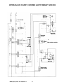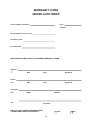
1
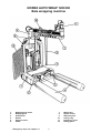
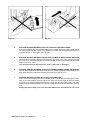
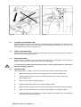
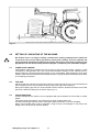
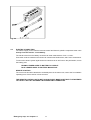
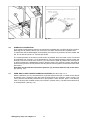
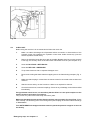
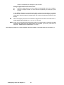
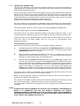
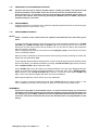
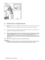
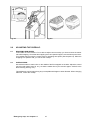
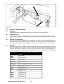
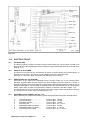
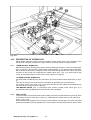
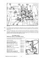
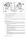
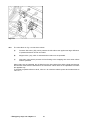
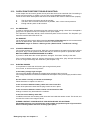
2 February 2003 USER'S MANUAL NORSE AUTO WRAP 1200 EH CHAP. CONTENTS PAGE 1.0 INTRODUCTION 3 2.0 SAFETY PRECAUTIONS 4 3.0 GENERAL INFORMATION ON BALEWRAPPING 8 4.0 10 5.0 6.0 15 SETTING UP / MOUNTING OF THE MACHINE EMERGENCY STOP* (Momentarily stop) 14 MOUNTING OF PLASTIC FILM 7.0 REMOTE CONTROL UNIT, CR 900 17 8.0 SPEED SETTING OF THE WRAPPING ARM 20 9.0 ADJUSTING THE OVERLAP 21 10.0 OPERATION INSTRUCTION 22 12.0 PERIODIC MAINTENANCE 24 13.0 ELECTRIC CIRCUT 26 14.0 DESCRIPTION OF HYDRAULICS 27 15.0 CHECK POINTS BEFORE TROUBLE SHOOTING 31 16.0 PROCEDURE OF TROUBLE SHOOTING 32 17.0 TROUBLE SHOOTING 33 18.0 HYDRAULIC CHART 35 19.0 WARRANTY TERMS 36 11.0 * Emergency stop: see chapter 2.1 1 NORSE AUTO WRAP 1200 EH Bale wrapping machine 1. 2. 3. 4. 5. 6. Wrapping arm motor Wrapping arm Prestretcher Rollers Support rollers Cutter * Emergency stop: see chapter 2.1 7. 8. 9. 10. 11. 12. 2 Main frame Speed control Stationary arm Lifting sling Emergency stop* Safety guard 1.0 INTRODUCTION. TELLEFSDAL A.S congratulates you with the choice of AUTO WRAP bale wrapping machine. We are certain you will be satisfied with the machine, and that you will have the pleasure of your investment for many years. The AUTO WRAP bale wrapping machine has more features than any other bale wrapping machine available. AUTO WRAP can pick up the bale, wrap and stack them without the operator leaving the tractor cab. This system is protected by patent law's almost world wide. AUTO WRAP 1200 EH is hydraulically driven by the tractors hydraulic system, and is controlled from the tractor cab by a remote control unit. The machine can either be mounted to three point linkage, front mounted with quick-couplers to the tractors frontloader or on a wheel loader. Then it's possible to stack the bales upon each other. AUTO WRAP 1200 EH is designed to wrap bales of grass, hey or straw, with nominal diameter of 3½ - 5½ ft. (110-170cm), and weights up to 1760 lbs. (800kg). The machine is developed and has been improved since the beginning in 1986, and is now a very reliable and safe machine with high security built in. This manual is meant to explain how AUTO WRAP is prepared, mounted, used and how it works, and shall together with the spare part's list be a reference for maintenance and troubleshooting. So take good care of the books, they are a part of the machine. Read carefully through this manual, and specially chapter 2.0, safety instructions, before starting the machine, and follow the instructions thoroughly. If problems should occur, check with chapter 17.0, and try to find out what is wrong. Ask your dealer for advice before you make the problem worse than it is. See also chapter 19.0, conditions of warranty. Technical Specifications AUTO WRAP 1200 EH Height in working position, min. / max. Width, min. / max. Length, min. / max. Weight Wrapping arm speed, recommended Wrapping arm speed, max. Bale size, max. Bale weight, max. Capacity Prestretcher Hydraulic connection Oil pressure / amount, min. Oil amount, max. Counter pressure, max. Electric connection 2280 / 2480 mm ( 7' 6" / 8' 2") 1290 / 2880 mm ( 4' 2" / 9' 5") 2170 / 3040 mm ( 7' 1" / 10') 615 kg (1356 lbs) 22 revolutions' per minute 27 revolutions' per minute ø1700 mm ( 5' 7") 800 kg (1765 lbs) Approx. 25 bales per hour 500 mm / 750 mm (20" / 30") 1 pcs. single working, + free return 180 bar / 15 litres per minute 40 litres per minute 10 bar 12 V DC TELLEFSDAL A.S can change the construction and/or technical specifications without warning and without rights to changes on already delivered products. © Copyright. All rights reserved. Any copying and reproduction of this manual are not permitted without permission from TELLEFSDAL A.S. With precaution of printing failure. * Emergency stop: see chapter 2.1 3 2.0 SAFETY PRECAUTIONS. TELLEFSDAL A.S does not take the responsibility for damages that may occur on machine, persons or other equipment, because of the machine NOT being used as described in this manual, or because of the safety precautions NOT being followed. 2.1 SAFETY EQUIPMENT. Before using the machine, make sure that all guards and covers are securely fitted. The machine must not be operated if a function does not work as described later in this manual. (See chapter 2.5). * EMERGENCY STOP. Auto wrap 1200 EH is equipped with a so-called emergency stop on the wrapping arm. This device stops all functions momentarily, but is per definition not an emergency stop, because it does not shut down the inputs. But it has the same function, so we have decided to call it an emergency stop in this manual. 2.2 BECOME FAMILIAR WITH THE OPERATIONS OF THE MACHINE. If you are unsure how to operate the machine properly, either use of or maintenance to your Auto Wrap, please contact your Auto Wrap dealer. 2.3 ADJUSTMENTS' / MAINTENANCE. Turn off the tractor and discharge the oil pressure before performing any adjustment or maintenance on the machine. Remember that a well maintained machine is a safe machine. 2.4 IMPORTANT! MAKE ALWAYS SURE THAT NOBODY IS IN THE HAZARD AREA OF THE WRAPPING ARM WHEN THE MACHINE IS IN USE. THE MACHINE MUST NEVER BE OPERATED BY PERSONS WHOM DOES NOT KNOW ENOUGH ABOUT HOW TO SAFELY OPERATE THE MACHINE, OR BY PERSONS UNDER 16 YEARS OF AGE. * Emergency stop: see chapter 2.1 4 Fig. 2-1 2.5 Fig. 2-2 DANGEROUS AREAS. TELLEFSDAL A.S has given the safety to the operator the highest priority, but it is still impossible to secure oneself of every danger area on the machine. Therefore we will now go through some of the dangers that can occur when using the Auto Wrap balewrapper. 1. PUNCH OF THE WRAPPING ARM. During the wrapping process the arm rotates with a speed of 20-27 revolutions per minute around the bale. On the arm there is mounted a prestretcher unit with a plastic roll. The speed on this can give a person serious injuries if one comes to close to the working area of the wrapping arm. To reduce this danger we have mounted an emergency stop* device on the wrapping arm, this stops all movement instantly when someone comes in the way of it. It is very important that this protection always works and that it should not under any circumstances be unconnected. (See more about the emergency stop* in chapter 5.0). 2. SQUEEZE-DANGER BETWEEN THE MAIN FRAME AND THE WRAPPING ARM. As earlier explained, we have a wrapping arm with a prestretcher and a plastic roll. Once every time around this wrapping arm passes the main frame. Here there may occur a squeeze danger if a person stands to close to the main frame when the wrapping arm passes. The distance between the main frame and the wrapping arm is not large enough to give place for a person. Between the prestretcher and the bottom frame there can also be a squeeze danger. To protect the user from this there is mounted a protection guard on the right hand side of the machine. You lift this up and turn it out on the side of the machine when operating the baler. You put it in transport position by lifting it up and turning it into the frame. (Fig. 2-1). The guard must not under any circumstances be removed, and if damaged it must be repaired before the machine is used again. 3. SQUEEZE-DANGER BETWEEN THE STATIONARY AND THE WRAPPING ARM. During the main wrapping process the wrapping arm moves around a stationary arm. Every time the wrapping arm passes the stationary arm, there is a squeeze danger that can be dangerous for the fingers. The distance between the stationary and the wrapping arm is between 25-40 mm. (See fig. 2-2). * Emergency stop: see chapter 2.1 5 Fig. 2-3 Fig. 2-4 4. SQUEEZE DANGER BETWEEN THE ROLLERS AND THE MAIN FRAME. During the wrapping process the bale rotates on two rollers. These two rollers rotate around the square pipe they are mounted on. Between the roller and the square pipe there is a squeeze danger for the fingers. (See fig. 2-3). 5. SQUEEZE DANGER BETWEEN TELESCOPE FRAME AND MAIN FRAME, INWARDS. When loading a new bale, the telescope frame moves into the main frame, and this is where there can occur a squeeze danger. This is secured with a cover on the telescope frame that slides on the main frame. The machine must not be used if this cover is removed or damaged. 6. SQUEEZE DANGER BETWEEN TELESCOPE FRAME AND MAIN FRAME, OUTWARDS. On both ends of the telescope frame there can occur a squeeze danger when loading a new bale. Keep therfore hands and feet away from this area. (See fig. 2-4). 7. SQUEEZE DANGER CAUSED BY PLASTIC AUTOMATION. At the end of the wrapping process the plastic shall be perforated and held tight until the start of the next wrapping process. When the cutter arm moves down to lock the plastic, there can occur a squeeze danger between the cutter arm and the cutter holder. The cutter blade that perforates the plastic is very sharp, so keep hands away from the cutter. (See fig. 2-5). Always put the security cover over the cutter blade when the machine is not in use. * Emergency stop: see chapter 2.1 6 Fig. 2-5 Fig. 2-6 2.6 LOCKING THE WRAPPING ARM. When the machine is not in use, make sure the locking bolt for the wrapping arm is mounted, and that the secure pin is fitted. If the bolt is not mounted, the wrapping arm and/or the machine could be damaged during transport. (See fig. 2-6). 2.7 THREE POINT MOUNTING. When the machine is mounted in the three point linkage, make sure that the lifting arms are tightend up so there is no sideways movement. 2.8 FRONT MOUNTING. If the machine is mounted on the front loader there must be a counterweight in the three point linkage. It must be large enough to give the tractor good stability. Connecting heavy working implements often has an overall negative effect on the tractor's driving and braking capacity. ! 2.9 TRANSPORTING. When transported on a public road there are certain safety measures that must be taken: 1. Make sure that the locking bolt on the wrapping arm is mounted. (Chapter 2.6). 2. Lift the protection guard, turn it into the machine and secure it with the locking pin. (See chapter 2.5.2). 3. Move the main rollers completly together. 4. Always transport the machine in the lowest possible position. 5. Make sure that the machine do not cover the tractors lights. If necessary, mount extra lights. 6. Make sure that at least 20% of the tractor's total weight is on the steering wheels. 7. If the machine is front-mounted, it's necessary to balance the weight with a counterweight mounted to the three-point linkage. * Emergency stop: see chapter 2.1 7 3.0 GENERAL INFORMATION ON BALE WRAPPING. 3.1 THE PRINCIPLE. The advantages of round bale ensilage are many, and include fewer feed units, a flexible harvesting system, large capacity and the possibility of selling feed units. In principle, the same fermentation processes occur whether the fodder is placed in a silo or pressed into bales and packed in plastic, i.e. lactic acid fermentation in anaerobic conditions. The oxygen in the bale must be exhausted before fermentation begins. The grass should be dried to approximately 30-40% solid content. The solid content can be determined by twisting the grass by hand. If drops of liquid are forced out of the grass, the solid content is less than 25%. Low solid content, (wet grass), can lead to increased butyric acid fermentation if preservatives are not added to the grass. If the solid content is too high, (over 50%), normal fermentation will not take place and there will be enough oxygen in the bale to produce mould fungus. 3.2 THE BALE PRESS. It is vital that the bale press produces compact, well-formed bales, as misshapen bales can be difficult to pack. Pressing will also often take longer, thereby increasing the amount of plastic used. 3.3 DIFFICULT BALES. When a misshapen bale is packed, it will have a tendency to move outwards or inwards on the rollers. If the bale begins to move outwards, the machine must be lifted slightly at the rear edge to get the bale to rest against the support rollers on the main frame. It can therefore be useful to use a hydraulic top stay to make this adjustment easier. (See chapter 4.2). If the support rollers almost disappear into the bale the machine should be pressed down slightly at the rear edge in order to remove the bale from the machine. The plastic can be damaged when friction against the rollers increases. Best results are achieved when the bale rolls easily against the support rollers all the time. If the bale to be packed is conical you must ensure that the sharp end is pointed at the tractor. It will then be easier to get the bale to lie correctly during packing. It is easy for such a bale to "turn" forward in the direction in which it is pointing, and therefore lie against the support rollers. If the bale is lying on a slope it must be picked up from the lower side. A hydraulic top stay will again be advantageous. 3.4 TYPES OF PLASTIC. A good type of plastic with good adhesive properties, and which is recommended for bale wrapping, must be used. The thickness of the plastic foil should be at least 25 µ. (25/1,000 mm). In order that the plastic tightens sufficiently around the bale, it is stretched before being wrapped, so it is somewhat thinner when it is put on the bale. With short-term storage, (up to eight weeks), it is recommended that bales have a minimum of four layers of plastic at the thinnest points, with at least 52-53% overlap. For long-term storage, or when the grass is wet when it is packed, the bale should have 90-100 µ plastic, (6 layers), and the same amount of overlap. If thinner plastic is used, more layers should be applied. If it is very hot the plastic will be stretched further, and more layers should be applied. It is better to have slightly too much than too little plastic on the bale. From experience, light plastic produces slightly lower temperatures within the bale, and tends to improve feed quality. * Emergency stop: see chapter 2.1 8 3.5 STORAGE LOCATION. Care should be taken in finding a suitable location for the storage of bales. The storage location should preferably be prepared before the bales are laid out. An elevation close to well-drained roads is recommended. If the wrapped bales are simply placed on stubble there is a danger of the plastic being pierced. A tarpaulin or a thin layer of sand should therefore be laid where the bales are to be stored over the winter. Bales should be stored in the shade as far as possible. This reduces the danger of air leakage in the bales. A bale which is stored in sunlight and which therefore undergoes greater swings in temperature "pumps in" a great deal of air in comparison to a bale which is stored in the shade. According to "Teknik for Lantbruket" [Technology for Agriculture] in Sweden, a bale which is stored in the shade has only 40% of the air leakage of a bale which is stored in sunlight. 3.6 STACKING / PROTECTION. If bales are hard and well formed, they can be stacked vertically, but loose and misshapen bales with low solid content should not be stacked higher than one layer, as this could easily cause deformity and the danger of runoff will be increased. Bales can also be stored on their sides. The layer of plastic is thicker here, providing greater protection against piercing. Bales should be covered with a tarpaulin or a fine-mesh net to protect against birds and small rodents. If the plastic is pierced, it must be sealed with weatherproof, hard-wearing tape, preferably under the outermost layer of plastic. Ensure that the hole is adequately sealed. 3.7 The best wrapping results are obtained by... i ...harvesting the grass early. i ...drying it out to 30-40% solid content. If there is a danger of rain, press and pack the grass anyway. i ...taking care not to mix any earth in with the grass. i ...using a press that produces even, firm bales. Bales 1.2 m in width and with a diameter of 1.2-1.5 m are the preferred sizes. i ...packing the bales soon after pressing, never later than two hours afterwards. i ...using a good type of plastic and six layers of plastic. This removes the need to use preservatives. i ...storing bales in the shade to reduce the danger of air leakage. * Emergency stop: see chapter 2.1 9 Fig. 4-1 4.0 SETTING UP / MOUNTING OF THE MACHINE. Be careful! There is a danger of being crushed when working implements are fitted and connected. Carry out the fitting procedures slowly and carefully, and use separate and approved lifting equipment to make the work easier. See section 2 on safety regulations and pay attention to the various safety decals displayed on different parts of the bale wrapper. ! 4.1 THREE POINT LINKAGE. AUTO WRAP 1200 EH is intended for rear mounting to the three point linkage, category 2. With considering of transportation are not the three point brackets mounted on the machine when it leaves the factory. (See spare parts list chapter 2-1 for more details). When attached to three point linkage, make sure the machine is level across the tractor. Tight up and lock the lifting arms so there is no sideways movement. 4.2 TOP LINK. Adjust the top link of the tractor so that the machine is level with the ground. It is recommended to use a hydraulic top link, as this makes it easy to adjust the angle of the machine. During the wrapping process it is recommended to tilt the machine towards the tractor, as this will prevent the bale from falling off the rollers. (See fig. 4-1). 4.3 FRONT MOUNTING. As extra equipment the machine can be equipped with quick-couplers for front loader or wheel loader. (See spare parts list chapter 2-2 for what types of quick couplers there are). You also need longer hydraulic hoses. (See spare parts list chapter 4-2 for more details). When front-mounted there must be mounted a large enough counterweight in the three point linkage, this is to secure the tractors stability. * Emergency stop: see chapter 2.1 10 Fig. 4-2 4.4 ELECTRIC CONNECTION. The electric supply for the machine's remote control and electro-hydraulic components must come directly from the tractors' 12 volt battery. The electric wires from the battery must have an area measurement of min. 2,5 mm2. Connection to other contacts on the tractor can cause risk of misfunctions, and is not to recommend. To secure the electric system against short-circuits there is an 10A fuse on the plus-leader, near to the battery pole. BROWN LEADER GOES TO BATTERY PLUS POLE BLUE LEADER GOES TO BATTERY MINUS POLE REMOTE CONTROL. The control unit should be attached to a suitable place in the tractor cab, next to the front loader's operating lever if the machine is front mounted. THE REMOTE CONTROL UNIT IS NOT SHOCK-PROOF. MAKE SURE THAT IT IS FASTENED TO A SOFT PAD THAT SECURES A NON-VIBRATING FOUNDATION. * Emergency stop: see chapter 2.1 11 Fig. 4-3 4.6 Fig. 4-4 HYDRAULIC CONNECTION. The hydraulic hoses between machine and tractor are equipped with 1/2" ISO male quick-couplers. Discharge the oil pressure before you connect the oil hoses. Use the tractors' hydraulic lever. To make sure that the balewrapper works properly, the tractors' oil pressure has to be at least 180 bar. The oil flow should be 15 - 25 litres per minute. The counter pressure on the return must be as low as possible, and not exceed 10 bar. This should be measured with a gauge. It is recommended to use one single-working hydraulic outlet and arrange a free return circuit to the oil tank. If you are unsure of what oil pressure the tractor gives, or what oil pressure the balewrapper receives, please contact your machinery dealer. Generally all tractors have got some counter-pressure in their hydraulic return systems. Some tractors have more than others. Hose with red cap shall be connected to pressure, (P), and hose with blue cap to the return. (T). (See fig. 4-3). 4.7 OPEN AND CLOSED CENTRE HYDRAULIC SYSTEM. (See also chap. 14.1). With the ball valve you can choose between a hydraulic system with open or closed centre. Almost all tractors have a hydraulic pump that gives a fixed oil flow per revolution. (Open centre). The valve, (with the red handle), shall then be in open position. Some tractors, (like f.i. John Deere), have an oil pump with variable volume per revolution. (Closed centre). The ball valve shall then be in closed position. (See fig. 4-4). * Emergency stop: see chapter 2.1 12 Fig. 4-5 4.8 CHECK LIST. Before using the machine it is recommended to follow this check list: 1. Make it a habit to discharge the oil-pressure before connection or disconnection of the hydraulic hoses. (By operating the hydraulic control lever inside the tractor). (Use the tractors hydraulic control lever). 2. Return-oil should be led as directly to tank as possible. Beware that if the counter pressure is too high, the security valve on the main block will release some oil. (See chapter 14.3). 3. Hose with BLUE CAP = RETURN OIL. 4. Hose with RED CAP = PRESSURE. 5. Tie up loose hoses so that no squeeze damages occur. 6. Remove the locking bolt that holds the wrapping arm to the frame during transport. (Fig. 4 5). 7. Make sure that the plug-in contact from the remote control is connected to the socket on the machine. 8. Start the tractor and try out the functions. A bale is not required for this test. 9. Check all connections, hoses and couplings. If there is any oil-leakage, it should be rectified immediately. If any problems should occur, it is most likely that the failure is in the quick-couplers on the tractors pressure and return-connections. They can be very narrow and work badly after some years. Make sure that both the male and the female-couplers opens properly for the oil flow. Check them carefully. The best thing to do is to exchange the quick-coupling on the return side and arrange a "free return". Your AUTO WRAP bale wrapper has been tested in practical operation in approx. 2 hours at the factory. * Emergency stop: see chapter 2.1 13 Fig. 5-1 5.0 EMERGENCY STOP*. 5.1 The machine is equipped with a safety guard on the wrapping arm, and its operation must be tested before work itself is started. 5.2 The safety guard is designed to stop the wrapping arm injuring operators or objects either when starting up or when wrapping bales. 5.3 The emergency stop* is constructed with a "positive" connection, i.e. it has to be in full order before the machine can be started. 5.4 It consists of a releaser hoop that activates a small electric switch. (See fig. 5-1). When the electric circuit is broken, the valve shuts off the oil, and the wrapping arm stops. This is shown in the display on the control-unit by three points lighting up. (See chapter 7.1.1, paragraph e). 5.5 When this function shall be tested, you start the wrapping arm. Hold out an arm or any obstacle. The wrapping arm shall now stop before it hits the arm. 5.6 To restart the machine the obstacle must be removed and the safety guard must return to its original position. If "STOP" (9) is pressed before "START" (8), the wrapping continues from the point in the program at which the emergency stop was activated. If, on the other hand, "STOP" (9) is pressed before "ZERO" (3), then the wrapping sequence starts from the beginning again. (See further in section 7.9.) 5.7 When the machine has been parked for some time, there might be copper acetate on the skidding rings, so there is no contact. If so, the machine cannot be started. Rub carefully off the rings with a fine rubbing paper. Clean it up with some alcohol or electric contact spray. NB! TO GET A RELIABLE MACHINE, IT IS VERY IMPORTANT TO ALWAYS KEEP THE SKIDDING RINGS AND BRUSHES CLEAN AND IN ORDER AT ALL TIME. * Emergency stop: see chapter 2.1 14 Fig. 6-1 Fig. 6-2 6.0 MOUNTING OF PLASTIC FILM. 6.1 When the plastic roll shall be mounted, you have to hold the prestretcher-rollers aside, Hold the rollers aside and put on the holding hook. (See fig. 6-1). 6.2 Place a reel of film on to the prestretcher's holding axle and put on the springloaded lock. 6.3 Pull the film between the rollers on the prestretcher in the direction of the arrow. (See fig. 6-2). (See also the sign on the wrapping arm). 6.4 The filmholder / cutter opens by pushing CUTTER OPEN, (5), on the remote control block. Pull out the film and place it over the U-shaped slot. 6.5 Push the CUTTER CLOSED-button, (4), and the film will be held in the U-shaped slot. 6.6 HEIGHT ADJUSTMENT OF PRESTRETCHER / PLASTIC FILM. The plastic film shall hit at the middle of the bale wrapped, and therefore it can be necessary to adjust the height of the prestretcher. (See more about this in chapter 10.2). If you use 500 mm plastic on a 750 mm prestrecher, then you can use the two distance sleeves to adjust the height on the plastic roll. There can be mounted one sleeve on each side of the plastic roll, or both sleeves can be mounted above or below. * Emergency stop: see chapter 2.1 15 7.0 CONTROL BOX Type CR 900-6. IMPORTANT ! Read this section on the function and operation of the control box thoroughly BEFORE using the machine! IN GENERAL DELTA CR 900-6 for Auto Wrap bale wrappers is a new control box specially designed for the new machines produced for the 1996 season. These machines have a number of working operations and consequently several different operations are programmed in the control box. This control box also replaces previous models and is therefore interchangeable with regard to connections, etc.. The control box automatically detects which wiring circuit it is connected to and consequently which machine it will be controlling. NOTE ! In order for the software in the control box to identify the machine to which it is connected and run the correct program, the service technicians and end user must follow the instructions for upgrading or changing machines and they must not make their own connections which could disrupt or damage this facility. IMPORTANT ! To avoid damaging or short-circuiting the control box it is very important that the electrical connections are made correctly, especially for the power supply from the tractor. Do not attempt to make any connections other than those described in section 4.9. * Emergency stop: see chapter 2.1 16 Fig. 7-1 INTRODUCTION In this section from point 7.1 up to and including 7.11 we first of all describe the working operations and single functions that are selected by the various buttons. The operator must study this part of the control box instructions as it covers everything that will be used on a regular basis. The second part, from point 7.12 up to and including 7.16, is concerned with reprogramming the control box and trouble-shooting. This, together with table 1, is necessary for anyone who wishes to alter any of the variable settings or values. These are chiefly to do with the length of time a sequence lasts: the time the wrapping arm, for example, takes from start-up to full speed. NOTE ! Alterations to the settings should only be carried out by service technicians as both skill and experience are required. If something is pressed accidentally so that the settings are altered or a particular alteration is not as intended, all the positions can be "reset" to the default values which were set up at the factory. This is done by pressing "BALES" (2) and "ZERO" (3) at the same time and keeping them pressed for about 3 seconds. (See section 7.13 for more information.) STARTING UP If a machine is attached when power is connected to the control box, the display will indicate u01 until "STOP" (9) is pressed. Then the program version is displayed, either u01, u02 or u03. This remains on the display until "START" (8) is pressed. Then the display shows the number of revolutions that have been programmed, and when "START" is pressed again the machine starts its wrapping sequence. The program which is displayed will be automatically saved and used in the next wrapping sequence as long as the power is not disconnected. IMPORTANT! If the power is disconnected on a machine which is not fitted with the new auto-detecting valve-operating cables, and the program is altered to u02 or u03, press "STOP" (9) three times. The machine will then be ready to start the wrapping sequence with the program that was entered before the power was disconnected. Before the operator presses "START" (8), he/she must make sure that the selected program version is appropriate for the type of machine that is attached. (See further in section 7.12.) If the wrapping arm rotates too fast, the display will start to flash. When the speed exceeds the danger limit of 27 rpm the wrapping arm stops automatically. To restart the process, the same procedure must be followed as is used after "EMERGENCY STOP" (10) has been activated. Pressing "STOP" (9) and "START" (8) once starts the process at the point at which the wrapping arm was stopped, while pressing " STOP" (9) and "ZERO" (3) once signals that the present sequence should be terminated, and that the sequence should start again at the beginning when "START" (8) is pressed. The control box is factory-programmed to cut out when the speed exceeds 27 rpm. If this programming is altered so as to increase the speed of the wrapping arm, THE TELLEFSDAL GUARANTEE WILL NO LONGER APPLY. DESCRIPTION OF FUNCTIONS Description of buttons on the control box. On the front panel of the control box there are 8 press-buttons for the functions, an LCD display and an emergency stop button. We will go through the various functions of the display and the different buttons, and describe the different combinations that are possible. Each particular button is described in the text both in terms of its function, e.g. "START", and in terms of its position as shown in the drawing of the control box (fig. 7.1), e.g. (2). * Emergency stop: see chapter 2.1 17 Explanation of fig. 7-2 The display has the following elements: a) 3 ½ digits, which means that it can display values up to 1999. b) 3 dots/full stops, which are used to indicate different situations. c) Plus or minus sign (+ or -). d) Colon ( : ). Fig. 7-2 7.1 7.2 LCD DISPLAY (1). The digital display (fig. 7-2) has the following functions: a) During normal operation indicates the number of revolutions made by the wrapping arm at any particular time. b) If control box button "BALES" (2) is pressed briefly, the display indicates the number of bales that have been wrapped. This remains on the display for about 10 seconds. The display then returns to the number of revolutions made by the wrapping arm during the current wrapping sequence. c) If the control box button "ZERO" (3) is pressed briefly, the display indicates the voltage supplied. If the voltage falls below 10 volts this is regarded as a break in the power supply and all functions are stopped. At the same time the display indicates the measured voltage and three dots are illuminated to show that the emergency stop* has been activated. d) The display indicates if the wrapping arm is rotating too quickly. All the figures on the display start to flash if the speed is too high. If the rotation speed exceeds the danger limit, the arm will stop automatically and the three dots, (e), will light up. In order to start the system again, the wrapping arm's speed must first be reduced and then press "STOP" (9), and then "START" (8). e) If "EMERGENCY STOP" (10) is pressed, or the safety guard on the wrapping arm is activated, three dots light up. When the emergency stop* is reset again, the dots are no longer illuminated. f) A dash lights up when the control box button "ZERO" (3) is pressed briefly. This indicates that the operator has chosen the number of revolutions indicated on the display as the selected value for the next wrapping sequence. g) Two dots light up when the selected value for the wrapping sequence is set to zero by pressing the control box button "ZERO" (3). "BALES" (2) This button has the following functions: a) When the machine is stopped: Pressing the button briefly makes the display indicate the number of bales that have been wrapped, up to 1,999 bales. This remains on the display for 10 seconds. If the "ZERO" (3) button is pressed while the number of bales is displayed, the counter will be returned to zero. d) If the "BALES" (2) and "ZERO" (3) are pressed simultaneously for about 3 seconds, all the settings are reset to the factory-programmed settings. See section 7.15 about programming. * Emergency stop: see chapter 2.1 18 7.3 "ZERO" (3) Functions that are active when a machine is stopped: a) If the button is pressed briefly after a wrapping sequence and when the number of revolutions is indicated on the display, the number of revolutions on the display will be saved and used as the selected value for the next wrapping sequence. When this has been saved, the minus sign (-) lights up on the display (when the button is released). b) When the button is pressed and held in for more than 3 seconds, the number of bales which is indicated on the display will be cancelled and permanently lost. After the cancellation the colon (:) lights up on the display. c) If interference or the random pressing of buttons has muddled up the settings that have been saved, press "BALES" (2) and "ZERO" (3) simultaneously for about 3 seconds. Then the colon (:) lights up, and the display shows 035. All settings are returned to the values programmed at the factory. See section 7.15. (Program u01 must have been selected in the first place, and the control box may have to make adjustments for the correct program version before the machine can be started.) Functions that are active only when the machine is operating: d) 7.4 "CLOSE CUTTER" (4) This button has the following functions: a) The cutter is closed (Relays K2 and K7) when the button is pressed. This function is disconnected when the machine is performing a wrapping sequence. b) When the machine is standing idle and this button is pressed simultaneously with "OPEN CUTTER" (5) and "START" (8), the operator will be able to alter important parameters (values) which apply to the wrapping sequence. See section 7.15 which deals with this. NOTE ! 7.5 When the "ZERO" (3) button is pressed briefly, the voltage measured on the machine is indicated on the display until the wrapping sequence is finished or until the button is briefly pressed again. When the machine is stopped, the button indicates the number of revolutions made by the machine, as usual. THE EMERGENCY STOP IS AUTOMATICALLY ACTIVATED IN THIS MODE. AS AN EXTRA SAFETY MEASURE "EMERGENCY STOP" (10) MAY BE PRESSED BEFORE GOING IN TO THE PROGRAMMING MODE. "OPEN CUTTER" (5) This button has the following functions: a) The cutter opens (Relays K1 and K7) when the button is pressed. When the machine is performing a wrapping sequence this function is disconnected. b) When the machine is standing idle and this button is pressed simultaneously with "CLOSE CUTTER" (4), and "START" (8), the operator will be able to alter important parameters (values) which apply to the wrapping sequence. See section 7.15 which deals with this. 7.6 "ROLLS IN" (6) When the button is pressed, the distance between the rolls is reduced. This function is always active except during emergency stop. (Relays K3 and K7.) 7.7 "ROLLS OUT" (7) When the button is pressed, the distance between the rolls is increased. This function is always active except during emergency stop. (Relays K4 and K7.) * Emergency stop: see chapter 2.1 19 7.8 7.9 7.10 "START" (8) This button has the following functions: a) When the machine is ready to wrap, the sequence is started by pressing this button briefly. If the machine has been stopped by "EMERGENCY STOP" (10), the machine will not start before "STOP" (9) is pressed and the 3 illuminated dots disappear from the display. b) When the machine is performing a wrapping sequence, but before it has reached the final part of the sequence, the operator can press "START" (8) and let the machine continue to wrap for as long as the button is pressed down. The number of extra revolutions increases by 1 each time the counter switch is passed. The number which appears on the display will be added to that of the original wrapping sequence. c) If the "START" (8) button is pressed quickly a given number of times during the wrapping sequence, the display will count the number of times it has been pressed, and this number will be added to the wrapping sequence. For a number of revolutions to be added the "START" (8) button must be pressed before the stopping sequence has commenced. If required this new value for the number of revolutions can be stored as the new selected value by pressing the "ZERO" (3) button briefly when the machine has stopped. d) If this button is pressed simultaneously with buttons (4) and (5) in order to start the programming sequence in the programming mode, the machine will be disabled by the emergency stop to protect against accidental start-up. "STOP" (9) This button has the following functions: a) When the machine is standing idle, this button can be pressed to make the machine run at slow speed for as long as the button is pressed. (Relays K5 and K7.) b) When the machine is performing a wrapping sequence, the machine will stop by following the normal stopping sequence when this button is pressed briefly. The stopping sequence commences the next time the counter switch is passed. c) When the machine has been stopped by the "EMERGENCY STOP" (10) and the 3 dots light up on the display, "STOP"(9) must be pressed briefly to cancel this status before "START" (9) can be pressed and the wrapping sequence be started at the point at which it was stopped. If the wrapping sequence is to be terminated and a new sequence started from the beginning, "ZERO" (3) must be pressed before "START" (8) is pressed. "EMERGENCY STOP" (10) This button has the following functions: a) It stops the wrapping sequence instantly, and cuts out all the power supply to the machine (via K11). Emergency stop is indicated on the display by 3 dots. An emergency stop can only cancelled by pressing "STOP" (9) briefly. Then the three illuminated dots disappear from the display and the machine is ready to start again in the wrapping sequence. If another function is to be used, "ZERO" (3) must be pressed first. NOTE ! The Emergency Stop for the machine is activated either by button number [10] on the control box, or by the emergency stop lever on the machine. Whichever is activated, both the processor and an independent circuit will ensure that a relay, K11, will physically interrupt all power supply to the machine. This disconnects all the functions. * Emergency stop: see chapter 2.1 20 Fig. 7-3 WRAPPING SEQUENCE 7.11 WRAPPING SEQUENCE FOR THE 1200 EH MACHINE This section describes a normal wrapping sequence for the AUTO WRAP 1200 EH. "S" is an abbreviation for wrapping sequence and the number after the S is the sequence number as illustrated in 7-3. This figure shows by means of drawings and display messages all the sequences of the wrapping process. NOTE ! THE STATED TIMINGS ARE THE STANDARD TIMINGS PROGRAMMED IN AT THE FACTORY. THE TIMINGS IN BRACKETS SHOW THE RANGE OF ADJUSTMENTS THE USER CAN MAKE TO THESE GIVEN STANDARD TIMINGS. (The program for the 1510/1514 and TWIN machines, u02 and u03 respectively, can only be used on 1510 machines supplied during or after the 1996 season.) Wrapping sequence S1: Press "START" (8), and the machine starts at slow speed. S2: The machine reaches full speed after approximately 3 seconds. (0.1 to 6.0 sec.) S3: After 2 revolutions plus 0.4 sec. (0.0-0.5 sec.), cutter up in 0.5 sec. (0.0-1.0 sec.) is activated. When this time is completed, the cutter drops in a fixed timing of 3 seconds. The selection of number of revolutions is made automatically as above, as long as table 1 address 0:26 is not adjusted. The automatic values, 002, are stored here. If the values are altered to anything else, the new values will be used whatever machine-type of control box is being used. S4: The machine wraps with a speed determined by the hydraulic oil flow. Every revolution is shown on the display, and the speed is calculated. During wrapping the following may occur: Wrapping speed exceeds certain limits: a) At a speed of over 2.7 sec. per revolution, i.e. 22 revolutions per second, the display will start to flash on and off. b) At a speed of over 2.2 sec. per revolution, i.e. 27 revolutions per second, the * Emergency stop: see chapter 2.1 21 machine is stopped by the emergency stop function. Voltage supplied falls below certain limits: a) When the voltage is below 10 V the voltage is automatically shown on the display. b) When the voltage is below 9 V the machine is stopped by the emergency stop function. If the "ZERO" (3) button is pressed briefly after a sequence has started, the voltage measured on the machine is shown on the display below the rest of the wrapping sequence information. When the button is pressed again, the number of revolutions will return to the display. S5: When the wrapping sequence has reached the programmed number of revolutions less 1, cutter up after 0.4 seconds, (0.0- 10.0 sec.) is activated. S6/S7: At the next counter pulse the programmed number of revolutions will be completed, and the speed will be reduced to half speed within 0.25 seconds. (0.0-10 sec.). After this has happened, cutter down in 2 seconds (0.0-10.0 sec.) The wrapping sequence is now completed, and the number of recorded bales will increase by 1. * Emergency stop: see chapter 2.1 22 7.12 TESTING THE CONTROL BOX This part of the description of the control box functions deals with the more technical aspects of programming and, as mentioned earlier, is intended for service technicians who need to alter any of the variable programmed values. There is a program in the control box for the wrapping process. The program has been altered and refined so as to achieve the best possible operation and suitability for the various AUTO-WRAP machines. In the course of time these machines have had various functions added which have required alterations to the program which is stored in the control box. Table I shows a so-called parameter which indicates which program has been selected. At the present time there are 3 different versions of the program. For ease of reference, the first program is called u01, and this is intended for the 1200 machines. This program may also be applied to the 1500 machines supplied up to and during the 1995 season. The second program, u02, is for the new 1510/1514 machine without the TWIN function. The third program, u03, is for 1510/1514 TWIN machines. The program version can either be selected manually by altering the parameter in table 1, or the new test program can determine which machine is attached. (For the 1510/1514 machines only) Checking functions, which automatically discover which machine is attached, are built in to the new control box DELTA CR 900-6 together with the new type of valve-operating cable, CV903-3.(1510/1514) The test program functions as follows: When power is connected to the control box, the following will always take place: a) The display lights up and indicates with three dots that "EMERGENCY STOP" is activated. This means that no functions can be started immediately. The following points require "EMERGENCY STOP" to be activated. b) When no machine is attached, the display shows: u01, i.e. program u01. This is the program that is normally selected at the factory. I.e. for all the 1200 machines and the versions up to and including 1995, of the 1500 machines. c) When a machine is attached, the display will show u01, until "STOP" (9) is pressed. Then the control box will test the contacts for the counter-pulse field to establish which type of machine (which type of valve-operating cable) is attached. This test is only performed when the power has been disconnected. When the test is completed, the program version is shown on the display, for example u01, u02 or u03. This remains on the display until "START" (8) is pressed. Then the display shows the number of revolutions that have been programmed, and when it is pressed again the machine will start the wrapping sequence. The version which is shown on the display will be automatically saved and used for the next wrapping sequence as long as the power is not disconnected. Before the operator presses "START" (8), he/she must make sure that the selected program is suitable for the machine that is attached. If the version is not suitable, "START" (8) must not be pressed. Instead, press "STOP" (9) one more time. This will call up table 1, address 22, where you can enter the correct version. If you call up table 1, address 22 accidentally, press "STOP" (9) again and the parameter table will be cleared. NOTE ! IN ORDER FOR THE SOFTWARE IN THE CONTROL BOX TO IDENTIFY THE MACHINE TO WHICH IT IS CONNECTED AND RUN THE CORRECT PROGRAM, THE SERVICE TECHNICIANS AND END USER MUST FOLLOW THE INSTRUCTIONS FOR UPGRADING OR CHANGING MACHINES AND THEY MUST NOT MAKE THEIR OWN CONNECTIONS WHICH COULD DISRUPT OR DAMAGE THIS FACILITY. * Emergency stop: see chapter 2.1 23 7.13 PROGRAM FOR THE WRAPPING PROCESS NB! If you are not sure how to alter the variable values, contact your dealer. The machine could be quite unusable if the variable values are set too far from the recommended values. If this should occur, it is simple to reset the normal factory-programmed values which can be used in the interim. This is done by pressing the "BALES" (2) and "ZERO" (3) buttons simultaneously for 3 seconds. 7.14 PROGRAMMING A table is stored in the control box which shows the important parameters which are used during the wrapping sequence. (See section 7.16.) 7.15 PROGRAMMING EXAMPLE NOTE ! Table 1 contains all the values which the operator himself/herself can alter within given limits. To call up the table, the following combination of buttons must be pressed simultaneously: "CLOSE CUTTER" (4), "OPEN CUTTER" (5) and "START" (8). The normal functions for the control box buttons will now be disconnected, and the buttons can only be used for altering the parameters which are stored in the table. When in programming mode the control box is set to Emergency stop to ensure that no functions can be accidentally started. When the button-combination has been pressed, and everything is ready for altering the values, the display will indicate 0:00 or 2:56. A colon signifies that the address is being shown for the current parameter (here the address means the line in the table). The address is altered by pressing "CLOSE CUTTER" (4) to reduce the value, while "OPEN CUTTER" (5) increases the value. Press "START" (8) to show the value for the selected address. The colon sign disappears and the display now shows the values of the selected address. To alter the value, press "OPEN CUTTER" (5) to increase it, and "CLOSE CUTTER" (4) to reduce it. To store the value, press "START" (8) again. At the same time the display will return and show the address. Buttons (4) and (5) may now be used to go to new addresses. When you wish to leave the programming level, press "STOP" (9) when the page number, i.e. the colon, is displayed, and then the control box is ready for use with the new values stored. REMEMBER! If you wish to program in all the default values, i.e. those set at the factory, the control box should be in the normal operating mode without a wrapping sequence being performed, and the "BALES" (2) and "ZERO" (3) buttons should be pressed simultaneously and held in for 3 seconds. Then all the values will be reset to the standard values as programmed in at the factory. * Emergency stop: see chapter 2.1 24 7.16 TABLE 1. The particular addresses and data which can be altered are listed in the table below. (Addresses with an asterisk (*) can be updated by "reset"). NOTE ! The stated timings are the standard timings programmed in at the factory. The timings in brackets show the range of adjustments the user can make to these given standard timings. Adr esse Normal value 1510/14 Range of adjustments Commentary User values * 0:05 085 * 0:06 238 0:07 000 No. of bales, lsb Constant, do not alter. 0:08 000 No. of bales, mid digit Read only. 0:09 000 No. of bales, msb Read only. 0:10 XXX No. of bales, lsb Read only. 0:11 XXX No. of bales, mid byte Total counter, read only. 0:12 XXX No. of bales, msb Total counter, read only. * 0:13 070 Constant Max. No. of revolutions in one wrapping sequence. * 0:14 005 000-010, where 005=0,5sec. Time for cutter up at film release. * 0:15 030 001-060, where 030=3,0 sec. Time from start to full speed. * 0:16 004 000-050, where 004=0,4 sec. Time after revolution pulse until cutter lifts up. * 0:17 030 001-100,where 030=3,0 sec. Time for cutter lifting up. * 0:18 025 000-100, where 025=0,25sec. Time from full speed to stop. * 0:19 020 000-100,where 020=2,0 sec. Time for cutter lowering at stop. * 0:20 120 Constant Max. Time for one revolution. (In addition to address 0:15) * 0:21 035 0-70 No. of revolutions in wrapping sequence. * 0:22 001 001-005 (001=u01, 002=u02, 003=u03) Program selection. * 0:23 003 001-010, where 003=0,3 sec. Applies only too the AUTO WRAP 1510/1514. * 0:24 0 000-100, where 000=0,0 sec. Applies only too the AUTO WRAP 1510/1514. (TWIN). * 0:25 (013) 000-050, where 013=1,3 sec. Applies only too the AUTO WRAP 1510/1514. (TWIN). * 0:26 002 001-009 (standard: u01=u02=2) No. of revolutions before the cutter releases the film. * 0:27 (001) 001-009 (standard: u03=1) Applies only too the AUTO WRAP 1510/1514. (TWIN). Constant, do not alter. * Emergency stop: see chapter 2.1 25 Fig. 8-1 8.0 SPEED-SETTING OF THE WRAPPING ARM. 8.1 Start the tractor and let it run at approx. 1000 revolutions per minute. Lift the machine clear of the ground. The oil flow to the machine is adjusted by two control valves on the machines' "shoulders". 8.2 The control valve on the "shoulder" where the hydraulic hoses come in to the machine, is for adjustment of the wrapping arm speed. (See fig. 8-1). 8.3 Adjust the wrapping arm speed to approx. 22 revolutions per minute. (Just below three seconds per revolution.) The adjustment is carried out by turning the wheel on the control valve. Turning clockwise REDUCES the speed and turning counterclockwise INCREASES the speed. It is recommended not to wrap with higher speed than 22 revolutions per minute, because then the plastic film will "catch" more air, and this air do not reach to evacuate from the bale. The result is bad fodder. OBS! Max. allowed wrapping arm speed is 27 revolutions per minute. REMEMBER! Increased speed of tractor engine do not increase the wrapping speed, it only increases the oil flow into the system and by that also the temperature in the hydraulic system. * Emergency stop: see chapter 2.1 26 Fig. 9-1 Fig. 9-2 9.0 ADJUSTING THE OVERLAP. 9.1 WRAPPING ARM SPEED. Load a bale on to the machine. To be able to adjust correct overlap, you have to leave the tractor cab while wrapping. Check that the wrapping arm has a speed of approx. 22 revolutions per minute. If not, adjust this by turning the control valve for wrapping arm speed. (See chapter 8.3). When the wrapping arm speed is OK, you can set the overlap. 9.2 OVERLAPPING. Use a black marker to mark a line on the middle of the film wrapped on the bale. Adjust the control valve for roller speed, (see fig. 9-1), so that the marker line is just covered. Approx. 52-53% is the ideal overlap. (See fig. 9-2). This adjustment can be kept as long as you wrap bales with approx. same diameter. When changing bale size, control the overlap. * Emergency stop: see chapter 2.1 27 10.0 OPERATION INSTRUCTION. We shall now go through a complete wrapping process, from loading to storage place, and explain the practical use of Auto Wrap 1200 EH. 10.1 LOADING. Pick a bale to wrap. Increase the opening between the rollers as much as possible. Lower the machine almost to the ground. Do not lower the machine all the way down to the ground. Drive in under the bale. Close the rollers until they begin to lift the bale. Lift the machine and the bale approx. 4"-6", (10-15 cm), above the ground. Close the rollers completely. The rollers must not under any circumstances hit the ground while closing. The reason why the rollers shall not hit the ground is that this will increase the wearing on the gears and the bearings of the rollers. 10.2 HEIGHT ADJUSTMENT OF TOWER / PRESTRETCHER. The tower is adjustable up or down after the bale size. It has three fixed adjustments. The tower and the wrapping arm with prestretcher are rather heavy, so it is recommended to use a tackle or the front loader to lift it. Tighten the properly after adjustment. The prestretcher has to be adjusted so that the plastic film is always hitting the middle of the bale. If you use a 500 mm film on a 750 mm prestretcher, the height of the film roll can also be adjusted with the two distance sleeves. (See chapter 6.6). 10.3 START. Remember that the plastic film end has to be locked in the U-shaped slot before starting the wrapping. When the plastic film end is in the slot, push "START" (8), and the wrapping arm now moves at ½ speed for approx. one half revolution before it automatically switches to full speed. This is to avoid damage of the film when starting. When the wrapping arm has done a couple of revolutions, the cutter-arm automatically releases the film end. (See also chapter 10.7). 10.4 OVERLAP. Control that the overlap is correct. If not, see chapter 9.0. 10.5 HOW MANY LAYERS OF PLASTIC FILM? When the bale is completely covered with film, read the counter that displays the number of revolutions done by the wrapping arm. This number has to be multiplied by 2 or 3, depending on how many layers of film you want to have. * 4 layers - multiply by 2. * 6 layers - multiply by 3. As long as you wrap bales with the same diameter, you can stop at the same number every time. 10.6 STOP. When the required number of revolutions is obtained, push the" STOP"-button(9). The wrapping arm will now rotate 1-2 revolutions, the cutter moves up, the arm speed is reduced and it stops at the right place for next wrapping cycles. Then the cutter is closing automatically, and the film is held tight in the U-formed slot and perforated. The bale is now completely wrapped and ready for stacking. 10.7 When the wrapping sequence is ended, give the ZERO-button(3) a short push, and a stroke lights up in the display. The stop-value is now stored in the memory, and the wrapping arm will automatically stop after the same number of revolutions by the next wrapping sequence. (The stroke will extinguish after the first revolution in next wrapping sequence). * Emergency stop: see chapter 2.1 28 10.8 If it later is required to change the number of revolutions stored in the memory, push the ZERObutton(3) for some seconds and the previously registered numbers are erased. This is confirmed by two lighting points in the display. 10.9 STORAGE PLACE. At the storage place the bales should be placed systematically. Start at the right-hand side, and stack to the left. The machine is lowered, but not all the way down to the ground. The rollers must not hit the ground. Push control "ROLLERS OUT" (7) and the bale will rest on the ground. Drive the tractor carefully away from the bale. Try to avoid touching the bale with the rollers. The plastic film will now tear off by the perforation at the cutter. Place the next bale to the left of the first one so that the loose film end on the last ball will be locked. Then you do not have to leave the tractor cab to fasten the loose film end. To be sure we recommend that you check that the film ends are securely fastened, and eventually fasten them a little bit better when you have stacked the bales. If the machine is front mounted, the bales can be staked upon each other. (See more in chapter 3.0). * Emergency stop: see chapter 2.1 29 Fig. 12-1 12.0 PERIODIC MAINTENANCE. 12.1 BEARINGS. All ball-bearings are packed with grease, and do not need any more maintenance. 12.2 PRESTRETCHER. If the machine is in daily use, the guiding sleeves at the prestretcher should be oiled once a week or when needed. Sprockets and bearings on the prestretcher should also be oiled when needed. 12.3 CUTTER / FILM HOLDER. The cutter / film holder is preadjusted from the factory and does not need further adjustments. By replacement of some spares it is necessary to adjust it. The springs for the U-shaped slot shall be adjusted so that they are almost completely squeezed together when the cutter-arm is all down. 12.4 GEAR OIL. The oil in the gearbox for the rollers must be exchanged after the first 100 working hours, and after that every 2000 hours or at least once a year. Clean up the gear inside with a suitable cleaner. Fill in new oil, the oil amount is approx. 0,5 litre. EP-gear oil in viscosity-group VG 150, (ISO 3448), or a similar type must be used. See list for confirmed oils. (Fig.12-1 shows plugs for filling and tapping). TYPE OF OIL +5° C / +40° C IV 95 min. (VG 150, ISO 3448) AGIP Blasia 150 ARAL Degol BG 150 BP MACH GR XP 150 CASTROL Alpha SP 150 CHEVRON Non leaded gear compound 150 ELF Reductelf SP 150 ESSO Spartan EP 150 I.P. Mellana 150 MOBIL Mobilgear 629 SHELL Omala oil 150 TOTAL Carter EP 150 * Emergency stop: see chapter 2.1 30 12.5 OIL LEVEL INSPECTION. The oil level must be checked monthly. If necessary, add oil of the same type. 12.6 OIL FILTER. The oil filter must be changed once a year. 12.7 HYDRAULIC CYLINDERS. Make sure that all hydraulic cylinders are closed when storing the machine. 12.8 QUICK COUPLERS. Be painstaking by keeping the quick couplers clean and apply the dust caps after use. 12.9 NYLON RAILS. The nylon rails on the telescope frame have to be cleaned and lubricated with oil. DO NOT USE GREASE! Soil and sand will easily stick to the grease, and then wear out the nylon rail much faster. Underneath the telescope frame there is a roller that must be greased regularly. 12.10 SKIDDING RINGS. Skidding rings and brushes for the emergency stop* have to be cleaned up regularly. Use alcohol or electric contact spray. If necessary, rub off the rings with a fine rubbing paper. (See also chapter 5.7). 12.11 STORAGE. The machine should be parked on a dry place during the closed season. 12.12 CLEANING. The machine should be cleaned and oiled regularly and by the end of the wrapping season. NOTE ! When using high pressure washing apparatus, care must be taken with the electrical installation. Also make sure that water is not sprayed directly into the bearings, etc.. Keep the control box protected from rain and water. If necessary use compressed air to dry electrical components. 12.13 STORAGE. The machine should be parked on a dry place during the closed season. * Emergency stop: see chapter 2.1 31 Fig. 13-1 13.0 ELECTRIC CIRCUT. 13.1 COUPLEFORM. The electric system consists of a remote control unit with supply line, control cable, (14-lead), with plug in both ends, and distributing lines to the different magnet valves and switches on the machine. (See fig. 13-1). 13.2 SUPPLY OF EL-POWER. The electric circuit must only be connected to 12 volt DC. Connect directly to the tractor battery, to avoid any loss of power. The fuse on the plus-leader must not be more than 10A. See chap. 4.4 and 4.8.7 about connection and setting up of the machine. 13.3 DESCRIPTION OF THE SYSTEM. All functions on the machine are operated from the remote control unit. It is a microprocessor operated, programmable unit that controls the whole wrapping process. When e.g. START is pushed, the wrapping arm motor starts at ½ speed. After a preprogrammed time it switches over to full speed. After approx. two revolutions it releases the film end, and switches over to ½ speed again before it stops when number of programmed revolutions is obtained. (See also chapter 7.11). The signals from the control unit are all the time sent to the magnet valves that shall be activated. The exit clips in the control unit are numbered from 1-14. 13.4 DISTRIBUTION OF POWER. (See fig. 13-1). When operating the machine the following valves shall be supplied with power simultaneously: 1. 2. 3. 4. 5. 6. 7. CUTTER opening ..................... CUTTER closing ....................... ROLLERS together ................... ROLLERS out ........................... WRAPPING ARM 1/2 speed .... WRAPPING ARM 1/1 speed .... CUTTER opening a little ........... * Emergency stop: see chapter 2.1 Power to No 1, 7 and 8 Power to No 2, 7 and 8 Power to No 3, 7 and 8 Power to No 4, 44, 7 and 8 Power to No 5, 7 and 8 Power to No 5, 6, 7 and 8 Power to No 1, 5, 6, 7 and 8 32 Fig. 14-1 14.0 DESCRIPTION OF HYDRAULICS. AUTO WRAP 1200 EH is driven from the hydraulic system of the tractor. The hydraulics of the machine can easily be changed from "Open Centre" to "Closed Centre" hydraulic system. 14.1 "OPEN CENTRE" HYDRAULIC. Most tractors have an oil pump which gives a certain quantity per revolution. Then the crane handle, (pos. 10, fig.14-2), has to be set in open position. (See chapter 4.7). If no other function is activated, the oil flows from the tractor, through the main valve block and back to the tank. When one of the functions on the control unit is operated, the master valve, (pos. 7, fig. 14-1) closes the oil flow circuit, and simultaneously the valve for the current function is opening. "CLOSED CENTRE" HYDRAULIC. For tractors with variable oil pump, like John Deere, the crane handle must be closed.(Pos.10, fig.4- 2) Then the oil can only come into the main valve block by operating one of the functions. The "closed centre" valve, (pos. 8, fig. 14-1), opens the oil flow into the block, and simultaneously the valve for the current function is opening. THE MASTER VALVE, (pos. 7), will always close, and the "closed centre" valve, (pos. 8), is automatically opening regardless of which function that is operated. 14.2 THE CUTTER. To prevent that the oil pressure to the cutter is falling, so that it not holds the film long enough, there is a piloted non-return valve, (pos. 9, fig.14-1), underneath the magnet valve on the main block. (Pos. 1-2, fig. 14-2). Underneath the above piloted non-return valve, inside the block, there is also a non-return valve that prevents that sudden pressure impulses in the return system can open the piloted non-return valve. * Emergency stop: see chapter 2.1 33 Fig. 14-2 14.3 The hydraulic system is equipped with a safety valve, (S1), which is preset to 185 bar. It opens for the oil circuit to tank if max. pressure is exceeded. This valve is attached to the main valve block. See fig. 14-2. 14.4 There is also a safety valve, (S2), on the return side in the main block. It works like an "emergency outlet valve", and lets the oil out on the ground if the return line should be blocked up. This valve is preset to 105 bar, and the valve's mission is to prevent that it by an accident can come high pressure into the return side of the wrapping arm motor. AUTO WRAP 1200 EH NUMERICAL ORDER OF THE MAGNET VALVES The numbers of the magnet valves are identical with the corresponding numbers on the electric leaders. Valve for CUTTER Valve for ROLLERS IN / OUT Valve for rotating the rollers when ROLLERS OUT is operated Valve for wrapping arm, ½ speed = Valve no. 1 - 2 = Valve no. 3 - 4 Valve for wrapping arm, full speed Master valve "Closed centre" valve Piloted non-return valve for CUTTER = Valve no. 6 = Valve no. 7 = Valve no. 8 = Valve no. 9 Main pressure limit valve Safety limit valve Power limit valve for wrapping arm Stop limit valve for wrapping arm Pressure limit valve for left roller motor = Valve S1 = Valve S2 = Valve S3 = Valve S4 = Valve S5 = Valve no. 44 = Valve no. 5 Fig. 14-3 * Emergency stop: see chapter 2.1 34 Fig. 14-4 14.5 Fig. 14-5 In order to get a soft conversion between START and STOP of the wrapping arm, the speed is divided in two steps. (This happens automatically). At ½ speed the magnet valve, (pos. 5, fig. 14-2), opens for oil to the wrapping arm, but it goes through a nozzle that limits the oil amount. At full speed also the magnet valve on the tower of the machine, (pos. 6, fig. 14-3), is opening, so that the oil goes outside the nozzle. 14.6 All three oil motors on the machine are serial-connected. At first the oil runs through the wrapping arm motor, then to the control valve for roller-speed, through each of the roller motors and returns to tank. 14.7 WRAPPING ARM VALVE BLOCK. The wrapping arm valve block is attached to the wrapping arm motor, and includes 4 valves. When the wrapping arm starts, the oil pressure also goes to the brake so it is released. But we want a little delay here to prevent a too hard stop when the brake goes on. This is obtained by the mounting of a nozzle inside the fitting to the brake. a) Non return valve. It shall prevent the oil of going back to the control valve for wrapping arm speed. It is placed inside the block, and can only be reached by removing the whole block from the motor. b) Safety valve on the plus side. (S4, fig. 14-4). This valve shall provide a gradual stop of the wrapping arm and prevent accumulation of pressure on the motor's outlet side when the arm stops. The valve lets the oil flow from the outlet side of the motor to the input side. c) Safety valve on the minus side. (S3, fig. 14-5). This valve limits the max. torque of the wrapping arm. The valve lets the additional oil over to the motors' outlet side. It is adjusted so that the pull force on the far end of the arm is approx. 35 KP. d) Holding valve. (Pos. 1, fig. 14-5). This valve regulates the oil flow on the outlet side to be able to hold a constant input pressure to the wrapping arm motor. This makes the motor go smooth, and the brake is not activated even if the wrapping arm rotates easy "downwards". (If the machine is in an oblique position while wrapping). * Emergency stop: see chapter 2.1 35 Fig. 14-6 14.8 The valve block on fig. 14-6 has three valves: a) Pressure limit valve, (S5), which protects the left roller motor against too large difference of pressure between oil inlet and outlet. b) Magnet valve, (44), which is activated when rollers out are operated. c) Non-return valve which prevents oil from flowing to the wrapping arm motor when rollers width is operated. When rollers out are operated, the oil flows from the minus-side of the width-cylinder and through the left roller motor before it flows back to the valve block. When rollers in are operated the oil flows the opposite way. To be able to operate rollers out at all, valve no. 44 must have electric power at the same time as valve no. 4. * Emergency stop: see chapter 2.1 36 15.0 CHECK POINTS BEFORE TROUBLE SHOOTING. In this chapter we have some general check points that have to be examined first if something is wrong with the machine. In chapter 17.0 we have a more detailed trouble shooting. There are three basic assumptions that have to be fulfilled if the machine shall function properly: 1. 2. 3. 15.1 The oil pressure from tractor should be 180 bar. The return flow of oil has to be as free as possible, max. 10 bar counter pressure. Enough electric power to all functions. OIL PRESSURE. In order to control that the oil pressure into the machine is high enough, there has to be applied a gauge to the oil pressure hose, for example on the quick coupler. If the pressure is less than 180 bar, there will be less power for the functions. The first place you trace this is at the ROLLERS OUT / IN. OIL AMOUNT. The oil amount that the tractor delivers must be minimum 15 liters/minute, but it is recommended that it is 25 liters/minute. (Max. allowed oil amount is 40 liters/minute). REMEMBER! Large oil amount = Valves get hot. (Small oiltank = insufficient cooling). 15.2 COUNTER PRESSURE. The counter pressure can be too high. With high counter pressure the machine's functions will get less power. High counter pressure means also that you need more power to operate the valves. MAX. ALLOWED COUNTER PRESSURE IS 10 BAR. If you are in doubt about the counter pressure, arrange a "free return" directly to the tank. If the counter pressure goes over 105 bar, the emergency outlet valve, (S2), will open and let the oil out on the ground through the outlet tube. (See chapter 14.4). 15.3 ELECTRIC POWER. It is important to check that all function gets enough electric power. If not, some, or all functions may fall out. Is the battery voltage high enough? The control box display indicates the voltage being supplied if this is too low. If the voltage falls below 10 volts this is treated as an interruption of the power supply and all functions stop. Are the cables correctly connected to the battery? Follow directions in chapter 4.4 and 13.0. Is the connection between battery cable and control unit OK? Clean off the poles and check that the plug comes correct in place. Is the connection between remote control unit and machine OK? Change contacts if any doubt about the condition. Is the fuse on the battery cable OK? In addition to the fuse on the battery cable, there is a fuse inside the remote control. This is 10A, and secures the current to the magnet valves. PLEASE CONTACT YOUR DEALER IF YOU ARE IN DOUBT OF ANYTHING. (Remember always to give your dealer the serial number and productionyear of your machine when contacting dealer and when ordering spare parts). * Emergency stop: see chapter 2.1 37 Fig. 16-1 BEWARE OF MOVING PARTS WHEN TESTING THE MACHINE. 16.0 PROCEDURE OF TROUBLE SHOOTING. 16.1 MAGNET VALVES. When you shall check if the magnet valves gets electric power, you do this in the following way: 1. Unscrew the nut that holds the solenoid. 2. The solenoid is easy to move without electric power. 3. Push the current function on the remote control. If the solenoid gets power, it will be difficult to move, it "sticks". This is the best and easiest way to check if the magnet valve gets electric power. Another way is to hold a screwdriver o.e. up to the magnet. If it "sticks", the solenoid gets electric power. The power supply to the valve can also be measured with a voltmeter, but then the contact must be connected to the solenoid, so it is using power. To have reliable functions, the voltage should not be lower than 11,5 volts, even if the magnet valve usually works with a little lower voltage. NB! Normally, repairs of magnet valves shall not be done by the dealers, but turned over to the manufacturer of the machine. This has to be agreed upon between the manufacturer and the importer. 16.2 Only for magnet valves to the main functions. (Pos. 1-5, fig. 14-2). If the electric supply is in order and one of the functions falls out, the reason can be a mote that tights or prevents the sliding shaft to open and/or close. Try to manoeuvre the function manually, by pressing the point of a screwdriver into the end of the valve housing. At the same time the corresponding switch on the control unit has to be operated to get electric power to the master valve. If the function is working again after this, the mote has been pushed out in the oil system and the machine can be operated normally again. 16.3 MASTER VALVE. To get anything to work, the master valve, (pos. 7, fig. 14-1), must have electric power. If there is no power supply to this valve, the oil goes straight back to the tank, and nothing happens. (For tractors with closed centre hydraulic, the "closed centre" valve, (pos. 8, fig. 14-1), always have electric power). (See also chapter 14.1 and 16.1). 16.4 EMERGENCY STOP*. The emergency stop* is constructed so that the electric circuit must be closed to be able to start the machine. As soon as it's broken, the machine will stop. This is shown on the control-units' display by three points lighting up. (See chapter 7.10). When the emergency stop* is activated, there shall be measured 4 volts over the emergency stop*-switch. * Emergency stop: see chapter 2.1 38 17.0 TROUBLE SHOOTING. 17.1 THE MACHINE DOES NOT FUNCTION. a) Even if the gauge shows enough pressure there is no reaction in the machine. The reason could be that one, (or both), of the quick-couplers does not open for the oil. Change quick couplers. b) The counter pressure could be too high. Max. allowed counter pressure is 10 bar. (See chapter 15.2). c) Make sure that the crane handle is turned into correct position. (See chapter 4.7). (Disturbances of this type, a, b or c, are most likely in the first days that the machine is in use). 17.2 CUTTER, WRAPPING ARM OR ROLLERS WIDTH DOES NOT FUNCTION. Each of the main functions, wrapping arm, cutter and rollers width has a separate magnet valve. If one of these functions falls out, and the electric supply is in order, the reason can be a mote that tights or prevents the sliding shaft to open and/or close. (See chapter 16.2). 17.3 THE CUTTER WILL NOT HOLD THE FILM. The pressure is falling and the springs start to lift the cutter. (See chapter 14.2). 17.4 THE WRAPPING ARM WILL NOT ROTATE. a) The bolt that secures the wrapping arm during transport has to be removed so that the wrapping arm can move free. b) The safety valve, (S3, fig. 14-4), can be leak, so that the oil is passing by the wrapping arm motor. Dismantle and try out if the sliding shaft can move freely. c) The wrapping arm valve, (pos. 5, fig. 14-2), is not working because of lack of electric power or a mote inside the block. See chapter 16.1. Clean it up or change the valve. d) The control valve, (fig. 8-1), can be blocked. Dismantle and try out if the valve works normally. Do not use sharp tools. e) Check if the oil motor is working. Ask your dealer for advice BEFORE you make the problems bigger and repairing more difficult. f) If the emergency stop* has been activated, the machine can be started again in two ways: 1) If "STOP" (9) is pushed befor "START" (8) ,will the wrapping continue from that point in the program where the emergency stop* was activated. 2) If "STOP" (9) is pushed before "ZERO" (3), the wrapping sequence will be reset, and the sequence starts from the beginning again. (See also chapter 5.6 and 7.10). Some possible trouble with the emergency stop*: 1. Bad contact of the skidding rings. Rub it carefully with fine rubbing paper. 2. The release hoop is out of position. Defect return spring or fragments in the fastening bracket. 3. The switch is defect. Replace. * Emergency stop: see chapter 2.1 39 17.5 17.6 THE ROLLERS WIDTH DOES NOT WORK. a) Does the magnet valve enough electric power? With many power consumers at the same time, the voltage can fall so much that all functions, or only the width-function does not work. b) Check the master valve. (Pos. 7, fig. 14-1). If it gets enough electric power and closes the oil flow, the failure has to be found in the magnet valve for rollers width. (See chapter 16.1). THE WRAPPING ARM IS ROTATING, BUT THE ROLLERS ARE NOT. Check first that the flow control valve for rollers is not closed. (Fig. 9-1). If the valve for rollers width, (3-4), fig. 14-2), are not in order, the oil that shall rotate the rollers can leak out through this valve, so the roller-motors are losing their power. To be able to loosen possible mote, the valve can be operated manually with a screwdriver at the end of the valve. (See chapter 16.2). 17.7 THE CUTTER DOES NOT LEAVE THE FILM WHEN THE MACHINE IS TESTED WITHOUT LOAD. The reason for this is that when the cutter is closed with maximum pressure it might be difficult to obtain sufficient pressure to open the piloted non-return valve, (underneath pos. 9, fig.14-2), if the machine is empty, i.e. wrapping arm and rollers unloaded. This will not happen while wrapping with a bale on the machine. If this should occur when testing without a bale, it can be avoided by not having the cutter closed with full pressure. Give a short push on control no. 5, CUTTER up, enough to release some of the pressure. * Emergency stop: see chapter 2.1 40 HYDRAULIC CHART, NORSE AUTO WRAP 1200 EH RIGHT ROLLERMOTOR OILFILTER LEFT ROLLERMOTOR ROLLER SPEED DOWN TWO-STEPS SPEED UP CUTTER IN WRAPPING ARM MOTOR WIDTH OUT WRAPPING ARM SPEED * Emergency stop: see chapter 2.1 41 19.0 WARRANTY TERMS. 19.1 TELLEFSDAL A.S. warrantees the NORSE AUTO WRAP 1200 EH bale wrapping machines for 12 full months from the date of purchase. 19.2 During the warranty period TELLEFSDAL A.S will repair, replace or test any parts proved to be defective in material or construction. 19.3 Before comprehensive warranty services are done, the warranty claim has to be agreed upon with TELLEFSDAL A.S. By approval of warranty claims TELLEFSDAL A.S covers all repair costs. Freight costs and all personal travel costs are normally the responsibility of the dealer. Before repairing the machine locally the terms of compensation have to be agreed upon between the buyer and the manufacturer. Compensation for defective parts corresponds to the current spare parts price-list, minus normal discount. If the warranty claim should be rejected, TELLEFSDAL A.S is not responsible for expenses incurred. 19.4 All claims must be presented in written form, on a fixed NOTICE OF CLAIM, and enclosed a copy of the warranty card, properly filled in. Guarantee claimed parts also have to be enclosed. All return shall be agreed upon before sending, and marked with serial number on the machine and the name and address of the dealer. Freight costs for returned parts have to be payed by the buyer. 19.5 The NORSE warrantee is NOT valid if: a) The warrantee card has not been filled out and a copy is not enclosed with the claim. b) The user's manual and safety instructions have not been followed. c) The machine has been misused, abused or carelessly operated. d) The machine is modified by welding or by attachments of not original parts and pieces. It has been serviced by persons, who are unauthorized by Tellefsdal A.S. e) The machine is re-programmed to contribute more than what is programmed at the factory. (Max. 27 rpm). 19.6 TELLEFSDAL A.S IS NOT responsible for lost working time or lost revenue that has resulted because of a defect in the machine. 19.7 The buyer can not claim a cancellation the purchase, a price-reduction or any other claims, if TELLEFSDAL A.S, within reasonable time, repairs the machine. 19.8 The buyer is granted credit on warranty claims AFTER approval from TELLEFSDAL A.S. Deductions of credits on current invoices is not accepted without prior agreement. 42 WARRANTY CARD NORSE AUTO WRAP Serial number of machine: Type: Serial number of control unit: Production year: Purchase date: WE HAVE READ AND ACCEPT THE CURRENT WARRANTY TERMS. Importer: Date Firm Signature Date Firm Signature Dealer: Customer: Name Address Signature HAVE YOU GOT ENOUGH TRAINING ABOUT THE MACHINE FROM YOUR DEALER? YES 43 NO 44