1
Low voltage electrical distribution
Micrologic
Control units
2.0 A, 5.0 A, 6.0 A, 7.0 A
2.0 E, 5.0 E, 6.0 E
User manual
04/2011
the
r
e
v
ic E
o
g
o
l
o
Disc
icr
M
w
it!
ne
n
u
l
ro
cont
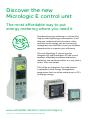
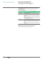
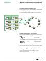
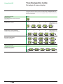
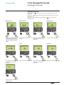
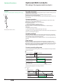
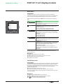
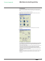
Discover the new
Micrologic E control unit
The most affordable way to put
energy metering where you need it
Distributed energy metering is a critical first
step to reducing energy consumption. It will
help you understand exactly where, when,
and how much energy you are consuming
throughout your facilities so you can discover
opportunities to improve your efficiency.
The new Micrologic E control unit for
Compact NS and Masterpact NT/NW circuit
breakers affordably combines protection,
metering, and communications in a way that is
smart, safe, and simple.
This will be an important first step toward
a complete Active Energy Management
programme that can often achieve up to 30 %
in energy savings.
www.schneider-electric.com/micrologic-e
* As part of a complete Active Energy Management programme
Contents
Discovering your control unit
2
Protection settings
4
Model designations
Presentation
Setting procedure Using the portable test kit
Setting the Micrologic 2.0 A/E control unit
Setting the Micrologic 5.0 A/E control unit
Setting the Micrologic 6.0 A/E control unit
Setting the Micrologic 7.0 A control unit
Selecting the type of neutral protection
2
3
4
5
6
7
8
9
Discovering the functions
10
Using the HMI
18
Maintenance
36
Current protection10
Overload and fault indications14
Measurements15
Trip history and pre-alarms17
HMI display modes18
Quick View mode (Micrologic E)
20
Tree Navigation mode
23
Resetting the fault indications Checking and changing the battery
Testing the ground-fault and earth-leakage functions
Optional functions
38
Technical appendix
46
Index
56
Optional M2C contacts Communication option
FDM121 front display module
Tripping curves Changing the long-time rating plug
Zone selective interlocking (ZSI)
Micrologic digital display
Thermal memory
Calculating demand values (Micrologic E)
RSU Remote Setting Utility
Measurement ranges and accuracy
04443724AA - 04/2011
36
37
38
39
41
46
48
49
50
51
52
53
55
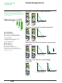
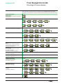
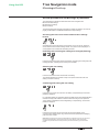
Micrologic 2.0 A and 2.0 E: basic protection
Micrologic 2.0 A
Micrologic 2.0 E
100 %
menu
long time
.7
.6
.5
.4
alarm
tr
8
(s) 4
.9
12
16
.95 2
.98 1
20
24
1
.5
.8
x In
Ir
long time
.7
.6
.5
.4
at 6 Ir
instantaneous
3 4 5
2.5
6
8
2
1.5
10
x Ir
Isd
6
8
10
x Ir
setting
Micrologic 2.0 A
I
Micrologic 2.0 E
X: type of protection
b 2 for basic protection
b 5 for selective protection
b 6 for selective + ground-fault protection
b 7 for selective + earth-leakage protection.
40 %
menu
tr
(s) 4 8 12
.9
16
.95
2
.98 1
20
24
1
.5
.8
x In
alarm
tsd
(s)
.4 .4 .3
.3
.2
.1
.7
.6
.5
.4
on
2
I t
Ii
.2
.1
0
delay
setting
long time
Ir
at 6 Ir
Isd 4
5
3
2.5
6
2
8
1.5
10
x Ir
Y: version number
identification of the control-unit generation.
"0" signifies the first generation.
menu
long time
.7
.6
.5
.4
t
100 %
40 %
short time
instantaneous
tr
(s) 4 8 12
.9
16
.95
2
.98 1
20
24
1
.5
.8
x In
0
Ir
Isd Ii
Long-time + short-time +
instantaneous protection
alarm
at 6 Ir
short time
8 10
12
4
15
3
2
off
x In
Isd 4
5
3
2.5
6
2
8
1.5
10
x Ir
6
tsd
(s)
.4 .4 .3
.3
.2
.1
on
2
I t
Ii
.2
.1
0
instantaneous
6
4
3
2
delay
setting
Micrologic 5.0 A
8 10
12
15
off
x In
I
Micrologic 5.0 E
Micrologic 6.0 E
t
DB119425
Micrologic 6.0 A
DB119424
Micrologic 6.0 A and 6.0 E: selective + ground-fault
protection
DB126351
Z: type of measurement
b A for "ammeter"
b E for "energy meter"
b P for "power meter"
b H for "harmonic meter"
b no indication: no measurements
Micrologic 5.0 E
100 %
Ir
DB119424
Micrologic 5.0 A
DB126332
Z
DB126331
Micrologic 5.0 A and 5.0 E: selective protection
DB126350
Y
at 6 Ir
3 4 5
2.5
2
1.5
setting
X
0 Ir
Isd
Long-time + instantaneous
protection
alarm
tr
8
(s) 4
.9
12
16
.95 2
.98 1
20
24
1
.5
.8
x In
instantaneous
Isd
t
2
Note: In this document, A/E signifies A or E when
characteristics are common to both Micrologic A and
Micrologic E control units.
I t on
100 %
100 %
40 %
menu
long time
.7
.6
.5
.4
Isd
tr
8
(s) 4
.9
12
16
.95 2
.98 1
20
24
1
.5
.8
x In
2.5
2
1.5
4 5
6
8
10
x Ir
alarm
tsd
.4 .4 .3
.2
.3
.1
.2
.1 2 0
(s)
on
setting
.7
.6
.5
.4
I t
Ii
instantaneous
8 10
12
4
15
3
off
2
x In
6
delay
Ig
D E F
G
C
H
B
I
A
.4 .4 .3
.2
.3
.1
.2
.1 2 0
(s)
I t
Isd
tr
8
(s) 4
.9
12
16
.95 2
.98 1
20
24
1
.5
.8
x In
2.5
2
1.5
4 5
x Ir
6
8
10
D E F
G
C
H
B
I
A
ground fault
tsd
.4 .4 .3
.2
.3
.1
.2
.1 2 0
(s)
on
setting
Ig
off
0
Ir
Isd Ii
Long-time + short-time +
instantaneous protection
alarm
at 6 Ir
short time
3
test
tg
on
long time
Ir
at 6 Ir
short time
3
2
I t off
40 %
menu
Ir
I t
delay
Ii
instantaneous
4
3
8 10
12
15
off
2
x In
6
test
tg
Ig
I 0
Ground-fault protection
I
.4 .4 .3
.2
.3
.1
.2
.1 2 0
(s)
on
I t
off
ground fault
Micrologic 6.0 A
Micrologic 6.0 E
Micrologic 7.0 A
t
DB119426
DB119424
Micrologic 7.0 A: selective + earth-leakage
protection
DB126352
DB126368
40 %
menu
Ir
t
100 %
40 %
Micrologic 2.0 E
DB119423
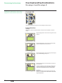
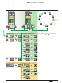
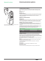
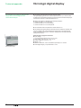
All Compact NS800-3200, Masterpact NT and
Masterpact NW circuit breakers are equipped with a
Micrologic control unit that can be changed on site.
The control units are designed to protect power circuits
and connected loads.
DB126330
Model designations
DB126349
Discovering your
control unit
t
100 %
40 %
menu
Ir
long time
.7
.6
.5
.4
.8
x In
tr
8
(s) 4
.9
12
16
.95 2
.98 1
20
24
1
.5
short time
Isd
4 5
3
6
2.5
8
2
1.5
10
x Ir
setting
alarm
at 6 Ir
tsd
(s)
.4 .4 .3
.3
.2
.1
on
2
I t
Ii
.2
.1
0
off
delay
instantaneous
8 10
12
15
2
off
x In
6
4
3
test
0
Ir
Isd Ii
Long-time + short-time +
instantaneous protection
I∆n
I 0
Earth-leakage protection
I
I∆n 5 7 ∆I 230 350
3
10
2
140
20
1
800
60
30
.5
earth leakage
Micrologic 7.0 A
04443724AA - 04/2011
DB126337
Presentation
DB126335
DB126367
Discovering your
control unit
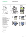
1
24 25 26 27
10
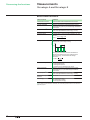
Micrologic 6.0 E
logic
Micro
6.0 E
32
32
12
12
11
9
13
100 %
30
13
31
40 %
100 %
29
alarm
menu
time
long
.8 .9
.7
.95
.6
.98
.5
1
.4 x In
Ir
5
tr
(s)
2
1
8 12
16
20
24
4
.5
@6
7
Indications
24LED indicating long-time tripping
25LED indicating short-time tripping
26LED indicating ground-fault
or earth-leakage tripping
27LED indicating auto-protection tripping
28LED indicating an overload
31
menu
14
15
18
.7
.6
.5
.4
.8
.9
.95
.98
1
x In
tr
(s)
4
8
2
1
.5
7
alarm
12
16
20
24
DB126355
DB126354
28
long time
Ir
15
@ 6 Ir
instantaneous
Isd
3 4 5
2.5
2
1.5
16
6
8
10
x Ir
Micrologic 2.0 A/E
14
17
16
21
20
tr
8
(s) 4
.9
12
16
.95 2
.98 1
20
24
1
.5
.8
x In
short time
tsd
. 4 . 4 .3
.2
.3
.1
.2
.1 2 0
(s)
on
setting
Ig
D
C
B
A
E
28
alarm
7
@ 6 Ir
Isd
4
5
3
2.5
6
2
8
1.5
10
x Ir
I t
off
delay
. 4 . 4 .3
.2
.3
.1
.2
.1 2 0
(s)
on
I t
Ii
instantaneous
off
14
15
19
33
34
16
17
22
ground fault
23
Micrologic 6.0 A/E
Isd
x In
2.5
2
1.5
x Ir
7
alarm
@ 6 Ir
short time
tsd
3 4 5
(s)
instantaneous
.4 .4 .3
.3
.2
.1
6
8
10
on
setting
2
I t
0
Ii
.2
.1
4
3
delay
6 8 10
12
15
off
2
x In
34
long time
Ir
.7
.6
.5
.4
tr
8
(s) 4
.9
12
16
.95 2
.98 1
20
24
1
.5
.8
x In
tsd
Isd
3 4 5
6
2.5
8
2
10
1.5
x Ir
(s)
(A)
3
2
1
.5
5
.3
.2
.1
7
instantaneous
.2
.1
2
I t 0off
(ms)
230
10
140
20
30
60
Ii
4
3
6
8
2
10
12
15
off
19
test
33
x In
delay
∆I
7
.4 .4 .3
on
setting
I∆n
28
alarm
@ 6 Ir
short time
8
10
4
12
3
15
off
2
x In
6
test
tg
F
G
H
I
.6
.5
.4
tr
8
(s) 4
.9
12
16
.95 2
.98 1
20
24
1
.5
.8
Micrologic 5.0 A/E
long time
.7
.6
.5
.4
long time
.7
19
34
Ir
Ir
17
setting
15
28
14
DB126338
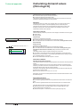
Adjustment dials
14long-time current setting Ir
15long-time tripping delay tr
16short-time pickup Isd
17short-time tripping delay tsd
18instantaneous pick-up Isd
19instantaneous pick-up Ii
20ground-fault pick-up Ig
21ground-fault tripping delay tg
22earth-leakage pick-up I∆n
23earth-leakage tripping delay ∆t
29
4
2
DB126336
1 top fastener
2 bottom fastener
3 protective cover
4 cover opening point
5 lead-seal fixture for protective cover
6 long-time rating plug
7 screw for long-time rating plug
8 connection with circuit breaker
9 infrared link with communication interfaces
10terminal block for external connections
11battery compartment
12digital display
13three-phase bargraph and ammeter
30
6
3
8
40 %
Ir
350
800
34
earth leakage
Micrologic 7.0 A
Navigation
29menu selection button
30menu scroll button
31"Quick View" navigation button
(Micrologic E only)
32fault-trip reset and battery test button
Test
33test button for ground-fault and earth-leakage
protection
34test connector
04443724AA - 04/2011
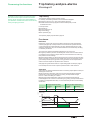
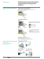
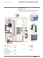
Setting procedure
Using the portable test kit
Protection settings
Setting procedure
DB126339
DB1126340
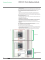
1. Open the protective cover.
5 E
A
5 E
800
2. Select the desired
setting.
The set value is
automatically displayed
on the digital screen in
absolute value with the
relevant units.
b Current in amperes
(A and kA);
b Tripping delays in
seconds.
DB126341
3. If no information is displayed, see "Micrologic digital
display" in the technical appendix. If no further action is
taken, the display returns to the main menu for current
measurements after a few seconds.
gic 5.0
Microlo
E
4. Close the protective cover and, if necessary, install a
lead seal to protect the settings.
100 %
40 %
3
Using the portable test kit
See portable test kit user manual.
DB126343
DB126342
To test the control unit, connect the portable test kit to the test connector.
5 E
gic 5.0
Microlo
E
100 %
40 %
m
2
04443724AA - 04/2011
Setting the Micrologic 2.0 A/E
control unit
See pages 10 to 12 for information on the available
settings.
The rating of the circuit breaker in this example is 2000 A.
DB119436
Protection settings
1
In 2000 A
In =
2000
A
Ir
long time
.7
.6
.5
.4
.8
x In
alarm
.9
.95
.98
1
In = 2000 A
DB119406
DB119478
Set the threshold values
t
Ir
Ir = 0.7 x In = 1400 A
Isd = 3 x Ir = 4200 A
instantaneous
Isd
Isd
3 4 5
2.5
6
2
8
10
1.5
x Ir
0
I
setting
long time
tr
(s)
2
1
4
.5
8
12
16
20
24
alarm
tr = 1 s
DB119440
DB119479
Set the tripping delays
t
tr
at 6 Ir
0
04443724AA - 04/2011
I
Setting the Micrologic 5.0 A/E
control unit
See pages 10 to 12 for information on the available
settings.
The rating of the circuit breaker in this example is 2000 A.
DB119436
Protection settings
1
In 2000 A
In =
2000
A
Ir
.7
.6
.5
.4
Isd
2.5
2
alarm
.8 .9
.95
.98
1
x In
Ii
4 5
3
x Ir
Ir = 0.7 x In = 1400 A
I2t ON curve
I2t OFF curve
t
t
Ir
instantaneous
Ii = 3 x In = 6000 A
Isd
6 8 10
4
12
3
15
2
off
x In
6
8
10
setting
Isd
Ii
Ii
I
0
4
at 6 Ir
short time
tr = 1 s
I2t ON curve
I2t OFF curve
t
t
tr
tsd = 0.2 s
tsd
.4 .4 .3
.2
.3
.2
.1
.1 2 0
I t
tr
tsd
(s)
on
DB119446
8 12
16
2
1
20
24
.5
(s)
alarm
DB119445
DB119481
tr
2
I t on
I
0
Set the tripping delays
long time
Ir
Isd = 2 x Ir = 2800 A
short time
1.5
In = 2000 A
DB119444
long time
DB119443
DB119480
Set the threshold values
tsd
2
I t off
0
I
0
I
delay
04443724AA - 04/2011
Setting the Micrologic 6.0 A/E
control unit
Protection settings
DB119436
See pages 10 to 13 for information on the available
settings.
1
In 2000 A
In =
2000
A
x In
.9
.95
.98
1
short time
C
B
Ii
A
4
3
6 8 10
12
15
2 x In off
Ii
Ig = 640 A
Ii
I
0
Ii = 3 x In = 6000 A
B
G
H
Isd
Isd = 2 x Ir = 2800 A
test
I
Ir
Isd
instantaneous
setting
D E F
t
Ir
Ir = 0.7 x In = 1400 A
Isd
3 4 5
6
2.5
2
8
1.5
10
x Ir
Ig
In = 2000 A
I2t OFF curve
DB119444
.6
.5
.4
.8
I2t ON curve
t
t
I
0
DB119451
.7
alarm
DB119443
long time
Ir
DB119450
DB119448
Set the threshold values
t
Ig
Ig
ground fault
0
I
0
I
2
1
short time
.5
8
12
16
20
24
tr = 1 s
.4 .4 .3
.2
.3
.1
.2
.1 2 0
(s)
ground fault
I t
delay
on
tr
2
I t
I2t on
test
.2
.1
0
off
tsd
tsd = 0.2 s
off
.4 .4 .3
.3
.2
.1
t
tr
(s)
tg
t
@ 6 Ir
tsd
on
I2t OFF curve
DB119446
(s) 4
I2t ON curve
I
0
I2t off
t
I
0
t
tg = 0.2 s
tg
0
04443724AA - 04/2011
tsd
DB119453
tr
alarm
DB119445
long time
DB119452
DB119482
Set the tripping delays
tg
I
0
I
Setting the Micrologic 7.0 A
control unit
See pages 10 to 13 for information on the available
settings.
The rating of the circuit breaker in this example is 2000 A.
DB126362
Protection settings
1
In 2000 A
In =
2000
A
.8 .9
x In
Isd
3 4 5
6
2.5
2
8
1.5
10
x Ir
(A)
2
1
.5
t
t
Ir
Ii
Ir
Isd
instantaneous
6 8 10
4
12
3
15
off
2
x In
setting
3 5 7
I2t OFF curve
Ir = 0.7 x In = 1400 A
1
short time
I∆n
In = 2000 A
.95
.98
I2t ON curve
DB126357
.7
.6
.5
.4
alarm
DB126356
long time
Ir
test
10
Ii
Ii
I
0
Ii = 3 x In = 6000 A
I∆n = 1 A
20
30
Isd
Isd = 2 x Ir = 2800 A
DB126358
DB126363
Set the threshold values
I
0
t
I∆n
earth leakage
0
I
tr
(s)
4 8 12
16
20
1
24
.5
tr = 1 s
alarm
2
I2t ON curve
I2t OFF curve
t
t
DB126360
long time
DB126359
DB126364
Set the tripping delays
tr
tr
@ 6 Ir
tsd = 0.2 s
tsd
.4 .4 .3
.2
.3
.1
.2
.1 2 0
(s)
on
∆t
I t
delay
(ms) 230
140
60
test
I2t on
I
350
0
I
I2t off
t
∆t = 140 ms
earth leakage
∆t
0
tsd
0
off
800
tsd
DB126361
short time
I
04443724AA - 04/2011
Selecting the type
of neutral protection
Protection settings
DB126372
On four-pole circuit breakers, it is possible to select the type of neutral protection for
the fourth pole:
b neutral unprotected (4P 3D)
b neutral protection at 0.5 In (3D + N/2)
b neutral protection at In (4P 4D).
/2
3D+N
4P 3D
04443724AA - 04/2011
4P 4D
Discovering the functions
Current protection
Micrologic A and Micrologic E
Protection settings
You can set the tripping curve of your control unit to match the needs of your
installation using the parameters presented below.
DB119427
Micrologic 2.0 A/E
t
1
2
3
0
Ir
Isd
I
Micrologic 6.0 A/E
Micrologic 7.0 A
t
t
t
1
2
I t on
2
DB119430
Micrologic 5.0 A/E,
6.0 A/E, 7.0 A
DB119429
DB119428
1. current setting Ir (long time)
2. tripping delay tr (long time) for 6 x Ir
3. pick-up Isd (instantaneous)
2
I t on
2
I t off
2
4
1
I t off
1
3
2
2
5
0
Ir
Isd
Ii
I
1. current setting Ir
(long time)
2. tripping delay tr
(long time) for 6 x Ir
3. pick-up Isd (short time)
4. tripping delay tsd
(short time)
5. pick-up Ii
(instantaneous)
0
Ig
I
1. pick-up Ig (ground
fault)
2. tripping delay tg
(ground fault)
I∆n
0
I
1. pick-up I∆n
(earth leakage)
2. tripping delay ∆t
(earth leakage)
Long-time protection
The long-time protection function protects cables (phases and neutral) against
overloads. This function is based on true rms measurements.
Thermal memory
The thermal memory continuously accounts for the amount of heat in the cables,
both before and after tripping, whatever the value of the current (presence of an
overload or not). The thermal memory optimises the long-time protection function of
the circuit breaker by taking into account the temperature rise in the cables. The
thermal memory assumes a cable cooling time of approximately 15 minutes.
Long-time current setting Ir and standard tripping delay tr
Micrologic control unit
Current setting
tripping between
1.05 and 1.20 x Ir
Time delay (s)
Ir = In (*) x …
tr at 1.5 x Ir
tr at 6 x Ir
tr at 7.2 x Ir
Accuracy 2.0 A/E, 5.0 A/E, 6.0 A/E and 7.0 A
0 to - 30 %
0 to - 20 %
0 to - 20 %
0.4
0.5
0.6
0.7
0.8
other ranges or disable by changing rating plug
0.9
0.95
0.98
1
12.5
0.5
0.34
300
12
8.3
400
16
11
500
20
13.8
600
24
16.6
25
1
0.69
50
2
1.38
100
4
2.7
200
8
5.5
* In: circuit breaker rating
The accuracy of the Ir setting may be enhanced by using a different long-time rating
plug.
See "Changing the long-time rating plug" in the technical appendix.
10
04443724AA - 04/2011
Discovering the functions
Current protection
Micrologic A and Micrologic E
For the characteristics and external wiring of the zone
selective interlocking function, see "Zone selective
interlocking" in the technical appendix.
The portable test kit can be used to test the wiring
between circuit breakers for the zone selective
interlocking function.
Short-time protection
b The short-time protection function protects the distribution system against
impedant short-circuits.
b The short-time tripping delay can be used to ensure discrimination with a
downstream circuit breaker.
b This function carries out true rms measurements.
b The I2t ON and I2t OFF options enhance discrimination with downstream
protection devices.
b Use of I2t curves with short-time protection:
v I2t OFF selected: the protection function implements a constant time curve;
v I2t ON selected: the protection function implements an I2t inverse-time
curve up to 10 Ir. Above 10 Ir, the time curve is constant.
b Zone selective interlocking (ZSI).
The short-time and ground-fault protection functions enable time discrimination
by delaying the upstream devices to provide the downstream devices the time
required to clear the fault. Zone selective interlocking can be used to obtain total
discrimination between circuit breakers using external wiring.
Short-time pick-up Isd and tripping delay tsd
Micrologic control unit
Pick-up
Time delay (ms)
at 10 Ir
I2t ON or
I2t OFF
Isd = Ir x … accuracy ± 10 %
settings
I2t OFF
I2t ON
tsd (max resettable time)
tsd (max break time)
2.0 A/E, 5.0 A/E, 6.0 A/E and 7.0 A
1.5
0
20
80
2
0.1
0.1
80
140
2.5
0.2
0.2
140
200
3
0.3
0.3
230
320
4
0.4
0.4
350
500
5
6
8
10
Instantaneous protection
b The instantaneous-protection function protects the distribution system against
solid short-circuits. Contrary to the short-time protection function, the tripping delay
for instantaneous protection is not adjustable.
The tripping order is sent to the circuit breaker as soon as current exceeds the set
value, with a fixed time delay of 20 milliseconds.
b This function carries out true rms measurements.
Instantaneous pick-up Isd
Micrologic control unit
Pick-up
Isd = Ir x … accuracy ± 10 %
2.0 A/E
1.5
2
2.5
3
4
5
6
8
10
8
10
12
15
OFF
Instantaneous pick-up Ii
Micrologic control unit
Pick-up
li = In (*) x … accuracy ± 10 %
5.0 A/E, 6.0 A/E and 7.0 A
2
3
4
6
* In: circuit-breaker rating
04443724AA - 04/2011
11
Discovering the functions
Current protection
Micrologic A and Micrologic E
Protection of the neutral conductor on four-pole
circuit breakers
Protection of the neutral conductor depends on the distribution system.
There are three possibilities.
Type of neutral Description
Neutral unprotected
Half neutral protection
(at 0.5 In)
Full neutral protection
(at In)
The distribution system does not require protection
of the neutral conductor.
The cross-sectional area of the neutral conductor is half that of the
phase conductors.
b The long-time current setting Ir for the neutral is equal to half the
setting value.
b The short-time pick-up Isd for the neutral is equal to half the setting
value.
b The instantaneous pick-up Isd (Micrologic 2.0 A/E) for the neutral is
equal to half the setting value.
b The instantaneous pick-up Ii (Micrologic 5.0 A/E / 6.0 A/E / 7.0 A) for
the neutral is equal to the setting value.
The cross-sectional area of the neutral conductor is equal to that of the
phase conductors.
b The long-time current setting Ir for the neutral is equal to the setting
value.
b The short-time pick-up Isd for the neutral is equal to the setting
value.
b The instantaneous pick-ups Isd and Ii for the neutral are equal to the
setting value.
Neutral protection for three-pole devices
Neutral protection is not available on three-pole devices.
12
04443724AA - 04/2011
Discovering the functions
Current protection
Micrologic 6.0 A/E, 7.0 A
Ground-fault protection on Micrologic 6.0 A/E
b A ground fault in the protection conductors can provoke local temperature rise at
the site of the fault or in the conductors.
The purpose of the ground-fault protection function is to eliminate this type of fault.
b There are two types of ground-fault protection.
Type
Description
Residual
Source Ground Return
b The function determines the zero-phase sequence current, i.e.
the vector sum of the phase and neutral currents.
b It detects faults downstream of the circuit breaker.
b Using a special external sensor, this function directly measures
the fault current returning to the transformer via the earth cable.
b It detects faults both upstream and downstream of
the circuit breaker.
b The maximum distance between the sensor and
the circuit breaker is 10 m.
b Ground-fault and neutral protection are independent and can therefore be
combined.
Ground-fault pick-up Ig and tripping delay tg
The pick-up and tripping-delay values can be set independently and are identical for
both the residual and "source ground return" ground-fault protection functions.
Micrologic control unit
Pick-up
Time delay (ms)
at 10 In (*)
I2t ON or
I2t OFF
Ig = In (*) x … accuracy ± 10 %
In y 400 A
400 A < In y 1200 A
In > 1200 A
settings
I2t OFF
I2t ON
tg (max resettable time)
tg (max break time)
6.0 A/E
A
0.3
0.2
500 A
0
B
C
0.3
0.4
0.3
0.4
640 A
720 A
0.1
0.2
0.1
0.2
20
80
140
80
140
200
* In: circuit-breaker rating
D
0.5
0.5
800 A
0.3
0.3
230
320
E
0.6
0.6
880 A
0.4
0.4
350
500
F
0.7
0.7
960 A
G
0.8
0.8
1040 A
H
0.9
0.9
1120 A
I
1
1
1200 A
Earth-leakage protection on Micrologic 7.0 A
b The earth-leakage protection function primarily protects people against indirect
contact because an earth-leakage current can provoke an increase in the potential of
the exposed conductive parts. The earth-leakage pick-up value I∆n is displayed
directly in amperes and the tripping delay follows a constant-time curve.
b An external rectangular sensor is required for this function.
b This function is inoperative if the long-time rating plug is not installed.
b q protected against nuisance tripping.
b kDC-component withstand class A up to 10 A.
Pick-up value I∆n and tripping delay ∆t
Micrologic control unit
Pick-up
Time delay (ms)
04443724AA - 04/2011
I∆n accuracy 0 to - 20 %
settings
∆t (max resettable time)
∆t (max break time)
7.0 A
0.5
1
2
3
5
60
140
140
200
230
320
350
500
800
1000
7
10
20
30
13
Overload and fault indications
Discovering the functions
Micrologic A and Micrologic E
Overload LED
DB126366
All Micrologic A and Micrologic E control units are
equipped with overload and fault indication LEDs.
long time
Ir
.7
.6
.5
.4
tr
8
(s) 4
.9
12
16
.95 2
.98 1
20
24
1
.5
.8
x In
@ 6 Ir
short time
Isd
4
5
3
2.5
6
2
8
1.5
10
x Ir
tsd
(s)
(A)
3
2
1
.5
5
instantaneous
. 4 .4 . 3
.3
.2
.1
on
setting
I∆n
alarm
0
2
I t
Ii
.2
.1
4
3
delay
test
∆t
(ms) 230
10
140
20
30
60
7
6 8 10
12
15
2
off
x In
350
100 %
40 %
800
earth leakage
This LED signals that the long-time current setting Ir has been overrun.
Fault indications
DB126347
DB126346
DB126345
DB126344
Important
The battery maintains the fault indications. If there are no indications, check the
battery.
Micrologic 6.0 E
Signals tripping due to overrun of the long-time current
setting Ir.
Micrologic 6.0 E
Signals tripping due to overrun of the short-time pickup Isd or instantaneous pick-up Isd or Ii.
Micrologic 6.0 E
Signals tripping due to overrun of the ground-fault pickup Ig or earth-leakage pick-up I∆n.
Micrologic 6.0 E
Signals tripping due to the auto-protection function of
the control unit.
The auto-protection function (excessive temperature
or short-circuit higher than circuit-breaker capacity)
opens the circuit breaker and turns on the Ap LED.
Important
If the circuit breaker remains closed and the Ap LED
remains on, contact the Schneider Electric after-sales
support department.
14
04443724AA - 04/2011
Measurements
Discovering the functions
Micrologic A and Micrologic E
Measurement and display possibilities
b Micrologic A measures instantaneous currents and stores the maximum values in
maximeters.
b In addition to the values measured by Micrologic A, Micrologic E measures
voltage, power and energy.
DB126369
Micrologic A and Micrologic E measurements can be displayed on:
b the digital screen of the control unit (see page 24 for Micrologic A and page 25 for
Micrologic E)
b an optional FDM121 Front Display Module (see page 41)
b a PC via the Modbus communication (COM) option (see page 38).
In addition, a bargraph on the front of the control unit continuously displays the
currents measured on phases 1, 2 and 3 as a percentage of the long-time current
setting Ir.
100 %
40 %
1.125 x Ir
1 x Ir
0.8 x Ir
0.6 x Ir
0.4 x Ir
The following table indicates Micrologic A and Micrologic E measurement and
display possibilities.
Measurements
Micrologic
A
E
Displayed on …
Micrologic FDM121
COM
Instantaneous currents I1, I2,
I3, IN, Ig (IDN) (1)
b
b
b
b
b
Current maximeters
I1max, I2max, I3max, INmax,
Igmax, (IDNmax) (1)
b
b
b
b
b
Demand current I1, I2, I3, IN (1)
b
b
b
b
Demand current maximeters
(peak demand) I1 max, I2 max,
I3 max, IN max (1)
b
b
b
Phase-to-phase voltages
V12, V23, V31 (3-wire and
4-wire systems)
b
b
b
b
Phase-to-neutral voltages
V1N, V2N, V3N (4-wire
systems) (2)
b
b
b
b
Average voltage Vavg
b
b
b
Voltage unbalance Vunbal
b
b
b
Instantaneous powers P, Q, S
b
b
b
Power maximeters
Pmax, Qmax, Smax
b
b
b
b
Demand active power P
b
b
b
Demand apparent power S
b
b
b
Demand power maximeter
(peak demand) Pmax
b
b
b
Instantaneous power factor PF
b
b
b
b
Active energy Ep
b
b
b
b
Reactive and apparent energy
Eq, Es
b
b
b
b
(1) The display of the Neutral current (IN) is available with Micrologic E when the parameter "type
of network" has been set to 4 Wire 4ct (44). See page 32.
(2) Important: for 3-pole circuit breakers used on 4-wire systems (3ph + N), terminal VN on the
Micrologic control unit must always be connected to the neutral. If this is not done, the phase-toneutral voltage measurements can be erroneous.
Note: If no information is displayed on the screen, see: "Micrologic digital display" in the
technical appendix.
04443724AA - 04/2011
15
Discovering the functions
Measurements
Micrologic A and Micrologic E
Measurement definitions
Measurements
Instantaneous current
Neutral current
Current maximeter
Definition
The rms value of the instantaneous time current.
Available with a 4-pole breaker
Maximum value of the instantaneous time current
(refreshed every 500 ms) since Micrologic installation
or last reset.
Mean of all instantaneous time current values over a
given user-adjustable time interval (e.g. 10 min).
The rms value of the voltage.
Average of the 3 phase-to-phase voltages V12, V23
and V31:
V12 + V23 + V31
V avg =
3
Demand current (1)
Voltage
Average voltage
Voltage unbalance on the most unbalanced phase,
displayed as a percentage of Vavg.
DB119998
Voltage unbalance
U
E max
V avg
0
V12
V23 V31
Micrologic E measures the maximum difference
between the instantaneous time voltage of each
phase and Vavg, and calculates the voltage
unbalance:
E max
V unbal =
V avg
Instantaneous power
Power maximeter
Demand power (1)
Instantaneous power
factor PF
Total energy
P: total active power
Q: total reactive power
S: total apparent power
P, Q and S are rms instantaneous values.
Maximum value of the instantaneous time power
(refreshed every 1 s) since Micrologic installation
or last reset.
Mean of all instantaneous time power values over a
given user-adjustable time interval (e.g. 10 min).
PF = P / S
Ep: total active energy
Eq: total reactive energy
Es: total apparent energy
(1) For details on how demand is calculated, see "Calculating demand values" in the technical
appendix page 52.
16
04443724AA - 04/2011
Trip history and pre-alarms
Discovering the functions
Micrologic E
Trip history
Micrologic E control units let you access information
that can be used to analyse or avoid circuit breaker
tripping, thereby increasing the overall availability of
your installation. Available information includes the trip
history and tripping pre-alarms.
The trip history displays the list of the last 10 trips.
For each trip, the following indications are recorded and displayed:
b the tripping cause: Ir, Isd, Ii, Ig or Auto-protection (Ap) trips
b the date and time of the trip (requires communication option) in order
to set Date and Time.
List of trip causes:
b overloads (Ir)
b short-circuits (Isd or Ii)
b ground faults (Ig)
b auto-protection (Ap).
The trip history display is presented on page 28.
Pre-alarms
Definition
Micrologic E control units can be set to deliver pre-alarms via their optional M2C
contacts (see page 38). These pre-alarms can be used to warn operators that the
current is approaching a trip threshold. In this way, remedial measures (e.g. loadshedding, maintenance, etc.) can be taken before the circuit breaker trips, avoiding
unnecessary shutdowns.
Two types of pre-alarms are available, depending on the control unit.
b Long-time protection pre-alarm: all Micrologic E control units can be set to deliver
a pre-alarm via one of their two outputs when the current reaches 90 % of the longtime protection current setting Ir.
b Ground-fault protection pre-alarm: Micrologic 6.0 E control units can also be set to
deliver a pre-alarm via one of their two outputs when the current reaches 90 % of the
ground-fault protection pickup Ig. Both Ir and Ig pre-alarms can be implemented if
neither of the two outputs are required for other functions.
See page 32 for general information on output settings (M2C contacts) or page 35
for an example of how to set an output to implement these or other functions.
Operation
The Ir and Ig pre-alarms are delivered via the non-latching outputs (M2C contacts) of
Micrologic E control units.
b Pickup (pre-alarm activation): when the current exceeds the pickup threshold
(equal to 90 % of the Ir current setting or Ig pickup), the output state changes
from 0 to 1 after a time delay of 1 second.
b Dropout (pre-alarm deactivation): when the current falls below the dropout
threshold (equal to 85 % of the Ir current setting or Ig pickup), the output state returns
to 0 after a non-adjustable time delay of 1 second and the pre-alarm is automatically
deactivated.
DB127875
Pickup (pre-alarm activation)
Dropout (pre-alarm deactivation)
Threshold
Time delay
Threshold
Time delay
Ir pre-alarm
90 % of Ir
1s
85 % of Ir
1s
Ig pre-alarm
90 % of Ig
1s
85 % of Ig
1s
% of Ir or Ig
90 %
Pickup threshold
85 % Dropout threshold
Pre-alarm
04443724AA - 04/2011
1s
1s
17
Using the HMI
HMI display modes
Definitions
b Micrologic A has a single display mode: Tree Navigation mode.
b Micrologic E has two display modes: Tree Navigation and Quick View modes.
Tree Navigation mode
buttons on a
b Tree Navigation is a manual scroll mode using the menu and
Micrologic A or E control unit.
b All information can also be viewed on an optional FDM121 Front Display Module
or on a PC using the communication option (see table page 38).
b Two navigation trees are provided for each Micrologic control unit:
v a Display tree to view the main values and settings of the control unit
v a Setting tree to modify the settings.
You can enter the Setting tree from any screen of the Display tree by pressing the
menu
and
buttons simultaneously.
b Each tree is divided up into several branches (see opposite page). Use the menu
button to scroll through the different branches of a tree. When on the last branch,
pressing the menu button returns you to the instantaneous I1 current screen of the
Display tree.
b Each branch provides access to values or settings that depend on the type of
Micrologic control unit, for example:
v measurements (instantaneous current, demand current, maximum instantaneous,
current, voltage, power, energy, etc.)
v trip history
v protection setting display
v settings (for modification of communication, measurement or output parameters).
b Use the
button to scroll through the different screens of a given branch. Press
the menu button at any time to proceed to the next branch.
b All the screens of the Micrologic A navigation trees are detailed on page 24.
b All the screens of the Micrologic E navigation trees are detailed on page 25.
Quick View mode
b Micrologic E also offers a Quick View display mode.
b This mode can be used to let the display automatically scroll through up to 10
screens.
b An override function is available to allow manual scrolling.
b Quick View is the factory-set display mode for Micrologic E. You can easily switch
between Quick View and Tree Navigation modes by briefly pressing the
button.
b You can modify the Quick View screens defined in the default configuration and
the screen display time.
18
04443724AA - 04/2011
HMI display modes
Using the HMI
Micrologic 5.0 A
Micrologic E
Micrologic 5.0 A
Current
DB126450
Micrologic A
Micrologic 5.0 E
Current
A
6308
A
7727
Current
Ph-Ph
Ph-N
voltage for voltage for
3W systems 4W systems
A
4632
V
V
266
Energy
100 %
MWh
6 233
V
100 %
40 %
40 %
V
270
100 %
Energy
40 %
MWh
V
285
V
Power
menu
menu
MW
menu
menu
Tree Navigation
Micrologic A display tree
menu
ppp
Max
A
ppp
tree by pressing the
Instantaneous and demand current
A
ppp
A
menu
Max. of instantaneous current
menu
You can enter the Setting tree from any screen of the Display
Micrologic E display tree
Instantaneous current
A
Quick View
ppp
menu
and
buttons simultaneously.
A
ppp
Max. of instantaneous current
ppp
Max
A
menu
Max
A
ppp
ppp
ppp
ppp
ppp
ppp
ppp
ppp
ppp
ppp
Max
A
Voltage
V
menu
V
Power
MW
menu
MW
Active energy
MWh
menu
MWh
Trip history
menu
Protection setting display
menu
A
ppp
Protection setting display
ppp
Micrologic A setting tree
Communication settings
ppp
menu
k A
A
menu
ppp
ppp
k A
Micrologic E setting tree
ppp
Communication settings
ppp
ppp
menu
W
Measurement settingsppp
menu
Min
MW
A
ppp
Min
MWh
s
Output settings (with optional
M2C
ppp
ppp contacts)
menu
Max
A
Software version
menu
04443724AA - 04/2011
19
Quick View mode (Micrologic E)
Using the HMI
Presentation
Quick View allows the operator to quickly view the most
important electrical measurements (currents, voltages,
active power, energy) without having to touch the
control unit keypad.
The screens automatically scroll in a circular manner so that the operator can view
all the main electrical measurements one after another.
The current bargraph and overload LED remain visible at all times in Quick View
mode.
Quick View screen descriptions
Quick View can be used to display the screens defined in:
b the factory configuration
b a custom configuration.
Screens defined in the factory configuration
Micrologic E control units come with a factory Quick View configuration including the
following 9 screens, scrolled in the indicated order:
1. Current of phase 1/A
2. Current of phase 2/B
3. Current of phase 3/C
4. Voltage: phase-to-neutral (V1N) or phase-to-phase (V12)
5. Voltage: phase-to-neutral (V2N) or phase-to-phase (V23)
6. Voltage: phase-to-neutral (V3N) or phase-to-phase (V31)
7. Total active power
8. Active energy: whole number part (up to 6 digits) in MWh
9. Active energy: last digit of whole number part plus 3 digits of decimal part
DB126520
Each screen is displayed for 2 s before being replaced by the next in the list.
This duration can be adjusted from 1 s to 9 s in 1 s steps (see "Measurement
settings - Quick View display duration" on page 30).
2 - Current
(ph 2/B)
3 - Current
(ph 3/C)
A
A
1 - Current
(ph 1/A)
A
4 - Voltage
4W (V1N)
4 - Voltage
3W (V12)
V
V
9 - Energy
MW
5 - Voltage
4W (V2N)
V
6 - Voltage
4W (V3N)
8 - Energy
V
5 - Voltage
3W (V13)
V
6 - Voltage
3W (V23)
V
7 - Power
MW
20
04443724AA - 04/2011
Quick View mode (Micrologic E)
Using the HMI
Use
Activating / Deactivating Quick View
Micrologic E
Instantaneous and demand current
Current
A
menu
ppp
A
ppp
Current
A
A
Screen 1
Screen 1
Current
Ph-Ph
Ph-N
voltage for voltage for
3W systems 4W systems
A
Max. of instantaneous current
V
V
menu
Max
A
ppp
ppp
Max
A
Energy
MWh
Voltage
V
V
menu
ppp
V
V
ppp
Energy
V
Power
V
Power
MW
menu
MW
ppp
ppp
MW
Active energy
Manual control of Quick View scrolling
DB126473
Automatic scrolling of Quick View screens can be stopped, for example to display a
screen for more than 2 seconds in order note measurements.
Press briefly
(< 1 s)
Stops scrolling and displays the
present screen for 20 s if no
other action is taken.
It is then possible to manually scroll through each Quick View screen one after the
other.
DB126473
DB126521
b When energised for the first time, Micrologic E automatically activates Quick View
and scrolls through the factory-configured screens.
b Press the
button briefly (<1 s) to activate the classical tree navigation mode.
Press again briefly (<1 s) to return to Quick View mode.
b In both Tree Navigation and Quick View modes, the first screen displayed is
screen 1. It shows the instantaneous current of the most heavily loaded phase. In
this example, screen 1 displays I1.
Press briefly
(< 1 s)
Displays the next screen for 20 s
if no other action is taken.
Returning to automatic scrolling
After a period of 20 s with no action, automatic scrolling is automatically reactivated.
Events causing the interruption of automatic
scrolling
Automatic scrolling of Quick View screens is also interrupted by the following events:
button)
b tripping (interrupted until the trip is reset by pressing the
b change in a protection setting
b battery test (while the test button is pressed).
04443724AA - 04/2011
21
Quick View mode (Micrologic E)
Using the HMI
Customisation
Custom Quick View configuration
b The Quick View factory configuration includes the 9 screens presented on the
page 20.
b It is possible to change some or all of the screens of the factory configuration.
b Quick View can scroll through up to 10 screens.
button briefly will have
b If all Quick View screens are removed, pressing the
no effect. The display remains in Tree Navigation mode.
Removing a screen
Display the screen
to be deleted.
To remove a screen from Quick View:
b make sure you are in manual control of the quick view mode, and if necessary,
press the
button briefly (< 1 s) to activate automatic scrolling and then press
the
button briefly (<1s) to activate the manual control of the quick view mode
b when the screen to be removed appears, press and hold the
button (> 4 s)
b when the message "OK dEL" is displayed, the screen has been removed.
Example: Removing the screen Current of phase 2/B
A
A
A
A
31
3150
Then press
briefly ( > 4 s)
A
302
3021
A
V
V
700
until the message
MWh
V
is displayed.
V
680
V
V
69
690
MW
Adding a screen
To add a screen (selected from the navigation tree):
b access Tree Navigation mode by briefly pressing the
button (< 1 s)
b in this mode, display the screen you want to add using the menu and
buttons,
as described in "Tree Navigation" on page 23.
b when the selected screen is displayed, press and hold the
button (> 4 s)
b when the message "OK Add" is displayed, the screen has been added to the
Quick View configuration. It will be placed in the last Quick View position.
kVAr
Display the screen
to be added.
MW
kVAr
kVA
kW
kVA
menu
Then press and hold (> 4 s)
MW
until the message
MW
is displayed.
b if you try to add a screen to an existing configuration that already has 10 screens,
the message "QV full" will be displayed.
22
04443724AA - 04/2011
Using the HMI
Tree Navigation mode
Presentation
Tree Navigation
b The classical navigation trees presented in the "HMI introduction" on page 19
provide access to all the screens of Micrologic A or Micrologic E control units.
b The different screens are accessible using the menu and
buttons and are
organised in branches corresponding to a given type of information.
The following branches are available, in the indicated order, depending on the type
of Micrologic control unit:
Branch (type of information)
Display tree
Instantaneous current
Instantaneous and demand current
Maximeters for instantaneous current
Voltage
Power (total of 3 phases)
Active energy (total of 3 phases)
Trip history (last 10)
Protection setting display
Setting tree
Communication settings
Measurement settings
Output settings (with optional M2C contacts)
Software version
Micrologic A
Micrologic E
b
b
b
b
b
b
b
b
b
b
b
b
b
b
b
Navigating with the keypad buttons
Press briefly
(< 1 s)
(symbol: a white hand)
Press and hold
(> 4 s)
(symbol: a grey hand)
Screen information
100 %
6 A current in the neutral
(arrow above the N).
100 %
100 %
360 A current in phase
1/A (arrow above 1/A).
V
100 %
380 V phase-to-phase
voltage between phases
1/A and 2/B (arrows
above 1/A and 2/B).
220V phase-to-neutral
voltage between phase
2/B and neutral (arrows
above N and 2/B).
DB126479
V
DB126478
A
DB126477
A
DB126476
DB126475
The positions of the downward arrows (one, two or three arrows) under the
information displayed on the screen indicate the phases concerned, as shown for
example in the screens below.
MW
100 %
2.556 MW total active
power of the 3 phases
(arrows above the 3
phases).
Default screen
Example: Phase 1 is the most heavily loaded.
DB126492
If no particular action is taken, the system displays the
instantaneous current of the most heavily loaded
phase.
A
100 %
04443724AA - 04/2011
23
Tree Navigation mode
Using the HMI
Micrologic A menu display
The figures below show all the screens of the 2 Micrologic A navigation trees with
all details concerning screen content and navigation between the various branches
and screens of the trees.
Display tree branches
Screens
Default display
(instantaneous current of the most heavily
loaded phase)
A
Instantaneous currents
I1
I2
I3
IN
A
A
Ig (Micrologic 6.0 A)
IDn (Micrologic 7.0 A)
A
A
A
menu
Instantaneous current maximeters
To reset current maximeters, see page 27.
I1
I2
I3
IN
Max
A
Max
A
Max
A
Max
Ig (Micrologic 6.0 A)
IDn (Micrologic 7.0 A)
A
A
menu
Protection setting display
(See details on page 29)
A
menu
A
S
A
A
A
∆
Setting tree branches
A
S
S
∆
S
Screens
Communication settings
(See details on page 30)
menu
24
04443724AA - 04/2011
Tree Navigation mode
Using the HMI
Micrologic E menu display
The figures below show all the screens of the 2 Micrologic E navigation trees with all details
concerning screen content and navigation between the various branches and screens of the trees.
Display tree branches
Screens
Default display
(instantaneous current of the most heavily
loaded phase)
A
Instantaneous and demand currents
I1
I2
A
I3
A
IN
Ig (Micrologic 6.0 E)
A
A
A
menu
I1
I2
A
I3
A
IN
A
A
menu
Instantaneous current maximeters
To reset current maximeters, see page 27.
I1
I2
A
Max
I3
Max
A
Max
IN
A
Max
Ig (Micrologic 6.0 E)
A
A
menu
Voltages (3-wire systems)
V
V
V23
V
V31
V
menu
Voltages (4-wire systems)
V12
V
V
menu
V1N
V2N
V
V3N
V
V12
V
V23
V31
V
V
V
menu
Power
Active Power is displayed positively or
negatively according to the parameter
Power sign (see page 32).
Active energy
Ep is displayed in MWh on 2 screens,
see details on page 26.
To reset active energy, see page 27.
P
PF
Q
S
kVAr
MW
Demand P
MW
kVA
menu
Ep (MWh)
Ep (MWh)
MWh
MWh
menu
Trip history
(see details on page 28)
The trip history displays the list of the last ten trips.
Protection settings display
(see details on page 29)
The protection settings displayed depend on the model of the Micrologic E control unit.
Setting tree branches
Communication settings
(see details on page 32)
Measurement settings
(see details on page 32)
Output settings (with optional M2C
contacts)
(see details on page 32)
Screens
W
k
menu
Min
MW
Min
A
menu
s
Ar
menu
Ar
Software version
menu
04443724AA - 04/2011
25
Tree Navigation mode
Using the HMI
Displaying total active energy
(Micrologic E)
Energy
The total active energy (Ep) consumed since Micrologic energisation is displayed on
2 screens:
b the first screen displays the whole number part of total energy in MWh
b the second screen displays the decimal part of total energy in MWh.
DB126496
Example: display of Ep = 26.233 MWh (26233 kWh)
MWh
MWh
menu
MWh
DB126511
DB126504
Display of whole
number part of total
energy in MWh (up to 6
digits)
Display of decimal part
of total energy in MWh
(up to 3 digits after the
decimal preceded by
the last digit of the
whole number part)
MWh
100 %
100 %
menu
menu
Press the "Arrow" button
to go to screen for the
decimal part.
Press the "Arrow" button
to go to screen for the
whole number part.
The total active energy (Ep) is calculated and displayed positively whatever
the value of the parameter Power sign. The Maximum totale active energy displayed
is 999 999 999 MWh. If the total active energy keeps increasing, the value displayed
is 999 999 999 MWh.
26
04443724AA - 04/2011
Tree Navigation mode
Using the HMI
Resetting current maximeters
and total active energy
Resetting the maximum current values
A
Max
Max
Max
A
A
menu
Max
A
Reset
Max
A
DB126495
Select the maximum
current value to be
reset (e.g. I2 max.)
DB126494
DB126493
DB127834
Reset of the corresponding memory register.
Select another value of
current to reset or
return to the main menu
Max
100 %
100 %
100 %
menu
menu
menu
Press the "Arrow" button
as many times as
required to access the I2
max. screen.
Press and hold the
"Arrow" button down for 3
to 4 seconds.
The old value flashes
during reset, then
changes to the present
value (the new
maximum).
A
Press the "Arrow" button
as many times as
required to select another
maximum value to reset
or return to the main
menu.
MWh
MWh
MWh
Reset
MWh
DB126485
Select the active energy
screen
Return to the main
menu
A
100 %
100 %
100 %
menu
menu
menu
Press the "Arrow" button
as many times as
required to access the
total active energy screen
(displaying the whole
number part of the total
active energy).
04443724AA - 04/2011
A
menu
DB127828
DB126504
DB127827
Resetting the total active energy (Micrologic E)
Press and hold the
"Arrow" button down
for 3 to 4 seconds.
The old value changes
to the new value (starting
at 0) when releasing
the button.
Press the "Menu" button
to return to the main
menu.
27
Tree Navigation mode
Using the HMI
Displaying the trip history (Micrologic E)
Introduction
DB126489
The trip history displays the list of the last 10 trips.
For each trip, the following indications are recorded and displayed:
b the tripping cause: Ir, Isd, Ii, Ig or Auto-protection (Ap) trips
b the date and time of the trip (requires communication option in order to set date
and time).
Example 1: Display for the first (most recent) trip of the five trips recorded in the trip
history.
Ir: tripping cause.
: symbol indicating trip history display
1: trip number (1 being the most recent)
5: total number of trips recorded.
Example 2: Display for the ninth trip of the ten trips recorded in the trip history.
DB126490
Ii: tripping cause.
: symbol indicating trip history display
9: trip number (1 being the most recent)
10: total number of trips recorded.
List of trip screens for the various causes
Cause
Comment
Ir trip
Long-time protection
Isd trip
Short-time protection
Ii (1) trip
Instantaneous protection
Ig trip
Ground-fault protection
Ap trip
Auto-protection
Screen display
(1) Instantaneous protection trips (Ii) are indicated on the trip history screen in the same way as
short-time protection trips (ISd). Both are caused by short-circuits.
Trip date and time
For each trip history screen, Micrologic E will display the date and time of the trip.
Every time the 24 VDC control voltage is energised, date and time restart at January
first 2000. Therefore, it is strongly recommanded to set date and time periodically
(at least once an hour).
The setting of the Micrologic E date and time requires the communication option
and can be set in one of 2 ways:
b via the front display module FDM121
b or using a supervision software (RCU, ION-Enterprise, etc.).
2 screens (date and time) will be displayed successively when the
button is pressed:
S
In this example, date is January third 2011 and time is 12 h 34 min and 56 s.
28
04443724AA - 04/2011
Using the HMI
Tree Navigation mode
Displaying the protection settings
DB119483
Micrologic control unit
2.0 A 5.0 A 6.0 A 7.0 A
2.0 E 5.0 E 6.0 E
Long-time current setting Ir
Select the "Settings"
menu.
The Ir value is displayed
first.
Long-time tripping delay tr
Press the "arrow" button
to go on to the tr value.
A
S
Short-time pick-up Isd
Press the "arrow" button
to go on to the
short-time Isd value.
Short-time tripping delay tsd
Press the "arrow" button
to go on to the tsd value.
A
S
Instantaneous pick-up Ii
the instantaneous Ii
value.
A
Ground-fault pick-up Ig
Press the "arrow" button
to go on to the Ig value.
A
or
Earth-leakage pick-up I∆n
the I∆n value.
A
∆
Ground-fault tripping delay tg
Press the "arrow" button
to go on to the tg value.
S
Or
Earth-leakage tripping delay ∆t
the ∆t value.
∆
Press the "arrow" button
to return to the
beginning of the menu.
04443724AA - 04/2011
S
A
29
Tree Navigation mode
Using the HMI
Micrologic A set-up
Set-up parameters
When the communication option is used with Micrologic A, the communication
parameters must be set. The following table lists these parameters and indicates
their possible values.
The procedure to change the settings is described on the next page.
Parameters
Definition
Format
(X = digit)
Default value
(units)
Default value
screen
Possible values
XX
47
1 to 47
Communication settings (1) for Micrologic A with communication option (Modbus network)
Modbus address
Unique Modbus address of Micrologic A
on the Modbus network to which it is
connected.
Baud rate
Number of kbits/s (kbauds) exchanged on XX.X
the Modbus network. It must be set to the
same value for all devices on the network.
19.2 (kb)
9.6 / 19.2
Parity
Used for error checking based on the
number of bits in the transmitted data
group.
E or n
E
E (Even)
n (None)
Language
Work language for the screens
En or Fr
En
En (English)
Fr ( French)
(1) When the communication option is used, the communication parameters must be set. The
communication module should be set up only when installed. Modification of a parameter on a
system already in operation may lead to communication faults.
30
04443724AA - 04/2011
Tree Navigation mode
Using the HMI
Micrologic A set-up
Setting procedure
b Briefly press the
parameter.
b Press the
parameter.
button to scroll through the possible settings for a given
button somewhat longer to save the setting and go on to the next
DB126887
Modbus address
DB126864
Metering menu
DB126863
DB126862
b After selecting the language, press and hold the
"Metering" menu.
button to return to the
Metering menu
A
menu
100 %
menu
menu
DB126889
Parity
100 %
menu
Then press and hold to save the
setting and go on to the next
parameter.
Select the desired baud rate.
Language
DB126890
Select the desired Modbus
address
You are in the "Metering" Menu.
Simultaneously press the two
buttons to access the parameter
settings for the communication
option.
DB126888
100 %
DB126896
100 %
100 %
100 %
100 %
100 %
menu
menu
menu
menu
Select the desired parity setting.
Then press and hold to save the
setting and go on to the next
parameter.
Select the desired language.
DB126897
Then press and hold to save the
setting and go on to the next
parameter.
100 %
menu
Press and hold to return to the
"Metering" Menu.
04443724AA - 04/2011
31
Using the HMI
Tree Navigation mode
Micrologic E set-up
Set-up parameters
The parameters are displayed in the order indicated in the table
below.
Parameters
Definition
Micrologic E has three types of set-up parameters:
b communication settings
b measurement settings
b M2c output settings.
The corresponding parameters (Address, Baud rate, etc.) have default values that
can or must be changed according to the needs of the installation or users.
The following table lists these parameters and indicates their possible values.The
procedure to change the settings is described on the next page.
Format
Default
Default
Possible values
(X = digit) value (units) screen (2)
Communication settings (1) for Micrologic E with communication option (Modbus network)
Modbus address
Address of Micrologic E on the Modbus network to which it is
connected.
XX
47
Baud rate
Number of kbits exchanged per second (kbauds on the
Modbus network).
XX.X
19.2 (kb)
Parity
Used for error checking based on the number of bits in the
transmitted data group.
E or n
E
Modbus connection
Type of Modbus connection:
4-wire (4) or 2-wire + ULP (ULP)
4 or ULP
4
1 to 47
4.8
9.6
19.2
k
E (Even)
n (None)
W
4
ULP
Measurement settings
Interval (window)
for demand power
calculation
Period of time over which the demand power is calculated.
XX
15 (minutes)
Interval (window)
for demand current
calculation
Period of time over which the demand current is calculated.
XX
15 (minutes)
Type of network
(3-wire or 4-wire)
and number of circuit
breaker poles (CTs).
b Setting 43 = 4-wire (3ph+N) and 3-pole CB (3 CTs) (3)
b Setting 44 = 4-wire (3ph+N) and 4-pole CB (4 CTs)
or 3-pole CB (3 CTs) + external CT
b Setting 33 = 3-wire (3ph) and 3-pole CB (3 CTs) (4)
XX
43
Power sign
By default, the Micrologic E considers power flowing into the
circuit breaker via the top terminals to loads connected to the
bottom terminals as positive (top fed).
+ or --
+
Quick View display
duration
Duration of display of each screen in Quick View mode
Min
Min
5 to 60
(in 1 minute steps)
MW
A
5 to 60
(in 1 minute steps)
43
44
33
+
--
2 (s)
1 to 9
s
Output settings for Micrologic E with optional M2C contacts
Output
Two outputs are available via the 2 optional M2C contacts:
b Out 1 and Out 2.
Setting possibilities are the same for both.
Out 1
Out 2
Event assigned to the
output
Various events can be assigned to each output:
b 3 trip events:
v tripping caused by Ir
v tripping caused by Isd or Ii
v tripping caused by Ig (Micrologic 6.0 E)
b 2 pre-alarm events:
v Ir pre-alarm
v Ig pre-alarm (Micrologic 6.0 E)
Not assigned
Ir trip
Isd (includes Ii) trip
Ig trip (6.0 E)
Ar
Ar
Output state
The output state (normally "0") can be controlled in three ways:
b forced to 1 (for testing)
b forced to 0 (for testing)
b changed from 0 to 1 (without latching) on occurrence of the
assigned event (normal mode)
Ir pre-alarm
Ig pre-alarm (6.0 E)
Forced to 1
Forced to 0
Normal mode (no
latching)
(1) When the communication option is used, the communication parameters must be set. The communication module should be set up only when installed.
Modification of a parameter on a system already in operation may lead to communication faults. (2) Note than all the default screens include a closed padlock icon
. This means the value is protected. You must open the padlock
to modify the settings and close the padlock after your modification in order to protect the
new value. The procedure is described on the next page. (3) Important: for 3-pole circuit breakers used on 4-wire systems (3ph + N), terminal VN on the Micrologic
control unit must always be connected to the neutral. If this is not done, the phase-to-neutral voltage measurements can be erroneous. (4) Important: for 3-pole
circuit breakers used on 3-wire systems (neutral not distributed), always set this value to 33 (see below) to avoid indications of a meaningless phase-to-neutral
voltage.
32
04443724AA - 04/2011
Using the HMI
Tree Navigation mode
Micrologic E set-up
General procedure to set Micrologic E parameters
The parameters are divided into three branches on the navigation tree:
b communication settings
b measurement settings
b output settings.
The following describes the general procedure to modify the settings. The next two
pages give examples for the Modbus address and output settings.
Accessing the first screen of the communication settings
branch
menu
Simultaneously press and hold (four seconds) the "menu" and "arrow" buttons to
access the first communication settings screen. The present value is displayed. A
closed padlock icon indicates that the setting is locked.
Unlocking and accessing the setting to be changed (flashing)
menu
Press the "Quick View" button to open the padlock. The setting to be changed (or the
first digit) will flash, indicating that it is ready to be modified.
Selecting the new setting
menu
Press the "Quick View" button to select the new setting.
The possible settings are scrolled in a loop. Each press increments to the next
setting or choices in the loop.
Confirming and locking the new setting
menu
Press the "arrow" button to confirm the new setting. It stops flashing and a closed
padlock is displayed.
For a two-digit setting, this operation sets the first digit and the second digit flashes to
indicate it is ready to be modified. Proceed as above to change it, then press the
"menu" button to validate the new two-digit setting. It stops flashing, and a closed
padlock is displayed.
menu
Press the "arrow" button to go to the screen for the next parameter in the
communication settings branch.To go to the next branch (measurement settings),
press the "menu" button.
Note: Within a given branch, the various parameters are organised in a loop. You must scroll
through all the parameters of the branch using the "arrow" button to return to the same
parameter.To proceed to the next set-up branch (or exit the last branch), press the "menu"
button.
04443724AA - 04/2011
33
Tree Navigation mode
Using the HMI
Micrologic E set-up
Example 1: Setting the Modbus address
k
menu
Modify the first digit
DB127036
Unlock and access the first
digit (flashing)
DB127034
DB127030
Access the existing Modbus
address
DB127035
DB127029
The Modbus address is a two-digit number identifying the Micrologic E in a Modbus
network.
Confirm the first digit and
access the second digit
(flashing)
100 %
100 %
100 %
100 %
menu
menu
menu
menu
Press the
button repeatedly
until the new value for the first
digit is displayed. You can scroll
through all possible values in a
loop (1).
Modify the second digit
Confirm and lock the new
setting (1)
Display next setting screen
DB127109
DB127110
button to open the
Press the
padlock and display the first digit
(e.g. 4). It will flash, indicating it is
ready to be modified.
DB127111
Simultaneously press the menu
and the
buttons for four
seconds to access the address
setting screen.
The existing address is displayed
(default address 47 or XX). A
closed padlock icon indicates
that the value is locked.
k
100 %
100 %
100 %
menu
menu
menu
Press on the
button
repeatedly until the new value for
the second digit is displayed. You
can scroll through all possible
values in a loop, as for the first
digit.
Press the
button again
to confirm and lock the new
setting. The second digit stops
flashing and a closed padlock is
displayed.
button to
Briefly press the
display the second digit. The digit
will stop flashing and the second
digit will start flashing, indicating
it is ready to be modified.
Briefly press the
button
again to go on to the next
parameter.
(1) The maximum address is 47. If you try to set a higher address, Micrologic will set the address
to the maximum address of 47.
34
04443724AA - 04/2011
Tree Navigation mode
Using the HMI
Micrologic E set-up
Example 2 : Setting Output 1 (for Micrologic E with
optional M2C contacts)
Ar
menu
Unlock and access the setting
menu
Simultaneously press the menu
and the
buttons for four
seconds to access the Modbus
address screen. Then press the
menu
button to access the output
setting screen.
The existing output setting is
displayed (default setting is
indicating that no trip event has
been assigned to the output). A
closed padlock icon indicates
that the setting is locked.
Confirm and lock the trip event
setting
Ar
100 %
100 %
100 %
menu
menu
menu
button to open the
Press the
padlock. The existing setting will
flash, indicating it is ready to be
modified
Confirm and lock the Output 1
state setting
DB127134
DB127133
Modify the output state control mode
Press the
button repeatedly
until the desired trip event is
displayed. You can scroll through
all possible events in a loop (see
list of possible events page 32).
Press the
button to confirm
and lock the new setting. The
setting stops flashing and a
closed padlock is displayed.
Display next setting screen
DB127135
100 %
Modify the trip event assigned
to Output 1
DB127132
DB127130
DB127113
Access the Output 1 setting
screen
DB127131
DB127112
The state of output 1 can be associated with the occurrence of a given trip event.
100 %
100 %
100 %
menu
menu
menu
Press the
button repeatedly until the
desired output state control mode is
displayed (see page 32). In normal mode,
the output goes from "0" to "1" (without
latching) on occurrence of the assigned
event.
04443724AA - 04/2011
Press on the
button to confirm
and lock the new setting. The setting
stops flashing and a closed padlock
is displayed.
Press the menu button again to go to
the screen for the next parameter.
35
Maintenance
Resetting the fault indications
Checking and changing the
battery
The procedure for closing the circuit breaker following
a fault trip is presented in the circuit breaker user
manual.
Resetting the fault indications
DB127800
b Determine why the circuit breaker tripped.
The fault indication is maintained until it is reset on the control unit.
b Press the fault-trip reset button.
Micrologic 7.0 A
Checking the battery
DB119486
Micrologic A
Press the battery-test button (same as the
fault-trip reset button) to display the battery
status.
Battery charged
Battery half charged
DB126472
Change the battery
Micrologic E
Press the battery-test button (same as
the fault-trip reset button) to display the
battery status.
Battery charge level displayed in percent
(100 %, 80 %, 60 %, 40 %, 20 % or 0 %).
%
If no information is displayed:
b either no battery is installed in the control unit;
b or an auxiliary power supply is required.
See "Micrologic digital display" in the technical appendix.
Changing the battery
2. Remove the battery.
DB119459
1. Remove the battery
cover.
DB119458
If the battery needs to be changed, order a new battery
with the Schneider Electric catalogue number 33593.
b Lithium battery.
b 1.2 AA, 3.6 V, 850 mA/h.
b SAFT LS3 SONNENSCHEIN TEL-S.
b Service life ten years.
100 %
40 %
+
4. Put the cover back in
place. Press the batterytest button to check the
new battery.
DB119461
DB119460
3. Insert a new battery.
Make sure the + and poles match the
indications.
100 %
40 %
36
04443724AA - 04/2011
Testing the ground-fault
and earth-leakage functions
Maintenance
DB126380
b Charge and close the circuit breaker.
b Using a screwdriver, press the test button for ground-fault and earth-leakage
protection. The circuit breaker should open.
gic 5.0
Microlo
E
100 %
40 %
Important:
If the circuit breaker does not open, contact the Schneider Electric after-sales
support department.
04443724AA - 04/2011
37
Optional M2C contacts
Optional functions
Micrologic E programmable outputs
Possible functions
The Micrologic E control unit can be equipped with up to two M2C contacts (S1 and
S2) that can be used to activate:
b alarms to signal and identify tripping caused by long-time, short-time,
instantaneous or ground-fault protection
b pre-alarms to warn of imminent tripping by ground-fault (Micrologic 6.0 E) or longtime protection.
484
474
DB127801
Important:
The M2C contacts require an auxiliary power supply.
Contact operation
The contacts can be set to change the state of Micrologic E outputs Out1 and/or
Out2 from 0 to 1 when certain events occur:
b trip events, i.e. when the control unit is tripped by:
v long-time protection Ir
v short-time instantaneous protection Isd or Ii
v ground-fault protection Ig (Micrologic 6.0 E only)
b pre-alarm events, i.e. when the current reaches 90 % of the following trip
thresholds:
v long-time protection setting Ir
v ground-fault protection pickup Ig (Micrologic 6.0 E only).
471
S1 S2
Wiring diagram for M2C contacts.
For details on how to assign different events to the contacts, see "Output settings" on
page 32 or the example on page 35.
Latching settings
When the output state setting is in "Normal mode" (see page 32), the contacts are
non-latching, i.e. the contact remains activated (state = 1) only as long as the event
that caused the change of state remains present.
Two other output state settings are available (forced to 1 or 0) for testing needs (see
page 32).
Time delays
b Pickup: when the current exceeds the selected tripping or pre-alarm pickup
threshold, the output state changes from 0 to 1 after a fixed time delay of 1 second.
b Dropout: when the circuit is opened by the circuit breaker or when the current falls
below the pre-alarm dropout threshold (see �����
page 17), the output state returns to 0
after a non-adjustable time delay of 1 second.
Contact operating diagrams
DB127847
Contact operating diagram for long-time, short-time, instantaneous and ground-fault
protection trip alarms
Ir, Isd, Ii or Ig pickup
tr, tsd or tg delay
t
Ir, Isd, Ii or Ig LED
Non-latching contact
Fault-trip reset
DB127875
Contact operating diagram for Ir and Ig pre-alarms
% of Ir or Ig
90 %
Pickup threshold
85 % Dropout threshold
Pre-alarm
38
1s
1s
04443724AA - 04/2011
Optional functions
Communication option
DB126379
Communication option
logic
Micro
5.0 E
100 %
40 %
menu
The communication option uses a Modbus communication protocol to remotely
access the following information and functions available in the Micrologic control
unit:
b status indications
b controls
b measurements
b operating assistance.
It consists of an independent communication module installed behind the Micrologic
control unit. This module receives and transmits information via the communication
network. An infra-red link transmits data between the control unit and the
communication module.
Modbus communication
Modbus bus
The Modbus RS 485 (RTU protocol) system is an open bus on which communicating
Modbus devices (Masterpact with Modbus COM, Power Meter, Sepam, Vigilohm,
etc.) are installed. All types of PLCs and computers may be connected to the bus.
Modbus communication parameters
The communication option consists of an independent module
that fits behind the Micrologic control unit.
For a Masterpact or Compact NS circuit breaker equipped with a Micrologic control
unit, the Modbus address, baud rate and parity are set using the keypad on the
control unit.
The Modbus communication system is divided into four managers that secure data
exchange with the supervision system and the circuit-breaker actuators.
The manager addresses are automatically derived from the circuit-breaker address
@xx entered via the Micrologic control unit (the default address is 47).
Modbus addresses
@xx
Circuit-breaker manager
(1 to 47)
@xx + 50
Chassis manager
(51 to 97)
@xx + 200
Measurement managers
(201 to 247)
@xx + 100
Protection manager
(101 to 147)
Number of devices
The maximum number of devices that may be connected to the Modbus bus
depends on the type of device (Masterpact with Modbus COM, Power Meter,
Sepam, Vigilohm, etc.), the baud rate (19200 bauds is recommended), the volume of
data exchanged and the desired response time. The RS 485 physical layer offers up
to 32 connection points on the bus (1 master, 31 slaves).
Each protection devices uses 1 or 2 connection points:
b a fixed device requires only one connection point (communication module on the
device)
b A drawout or withdrawable device uses two connection points (communication
modules on the device and on the chassis).
The number of devices must never exceed 31 fixed devices or 15 drawout/
withdrawable devices.
Bus length
The maximum recommended length for the Modbus bus is 1200 m.
Bus power source
A 24 V DC power supply is required (less than 20 % ripple, insulation class II).
04443724AA - 04/2011
39
Optional functions
Communication option
Data and functions available via the communication
option
Masterpact and Compact NS circuit breakers equipped with Micrologic control units
and the Communication option can be integrated in a Modbus communication
environment. In this case the following information and functions are available
remotely.
Micrologic
A
E
Status indications
ON/OFF
b
b
Spring charged CH
b
b
Ready to close PF
b
b
Fault-trip SDE
b
b
Connected/disconnected/test position (via CE/CD/CT contacts of
optional chassis communication module)
b
b
MX1 opening release
b
b
XF closing release
b
b
Controls
Measurements
Current
Instantaneous currents I1, I2, I3, IN, Ig, IDN
b
b
Current maximeters: I1max, I2max, I3max, INmax, Igmax, IDNmax
b
b
Average current Iavg
b
Current unbalance Iunbal
b
Demand current
Demand currents I1, I2, I3, IN
b
Demand current maximeters (peak demands)
I1 max, I2 max, I3 max, IN max
b
Voltage
Phase-to-phase voltages V12, V23, V31 (3-wire and 4-wire systems)
b
Phase-to-neutral voltages V1N, V2N, V3N (4-wire systems) (1)
b
Average voltage Vavg
b
Voltage unbalance Vunbal
b
Power
Instantaneous power P, Q, S
b
Demand power P, S
b
Demand power maximeters Pmax
b
Instantaneous power factor PF
b
Energy
Total Energy Ep
b
Total Energy Eq, Es
b
Operating assistance
Setting of the control-unit date and time
Functional unit (IMU) name
b
b
b
Power sign
b
Interval for the demand-current calculation window
b
Interval for the demand power calculation window
Battery-charge indication
b
b
Trip histories
Operation counter
b
b
b
Assignment and setup of programmable contacts (M2c)
b
b
Protection
Circuit-breaker rated current
b
b
Type of neutral protection
b
b
Long-time I2t protection settings
b
b
Short-time protection settings
b
b
Instantaneous-protection settings
b
b
Ground-fault protection settings
b 6.0 A
b 6.0 E
Earth-leakage protection settings
b 7.0 A
(1) Important: for 3-pole circuit breakers used on 4-wire systems (3ph + N), terminal VN on the
Micrologic control unit must always be connected to the neutral. If this is not done, the phase-toneutral voltage measurements can be erroneous.
40
04443724AA - 04/2011
FDM121 front display module
Optional functions
The ULP System
Definition
PB106672-176
ULP (Universal Logic Plug) is a connection system that can be used to build an
electrical distribution solution integrating metering, communication and operating
assistance functions for Masterpact and Compact NS circuit breakers.
1
2
3
4
5
1
6
6
7
14
13
12
11
8
9
10
4
1
2
3
BCM ULP: Breaker Communication Module with ULP port
Micrologic control unit
LV434195
Breaker ULP cord
0.35 m
1.3 m
LV434196
3m
LV434197
4
5
6
7
8
9
10
11
12
Modbus cable
Ethernet cable
FDM121: Front Display Module
ULP line terminators
CCM: Chassis Communication Module
EGX100: Ethernet gateway
External 24 V DC power supply
Modbus interface
Stacking accessory
04443724AA - 04/2011
TRV00121
TRV00880
33852
13 ULP cable
0.3 m
0.6 m
1m
2m
3m
5m
14 NSX cord
0.35 m LV434200
1.3 m LV434201
3m
LV434202
TRV00803
TRV00806
TRV00810
TRV00820
TRV00830
TRV00850
TRV00210
TRV00217
41
Optional functions
FDM121 front display module
The ULP system can be used to enhance the Masterpact and Compact NS circuit
breaker functions by:
b local display of measurements and operating assistance data on the switchboard
with the FDM121 front display module (firmware version u V2.1.0)
b setup and maintenance functions with the maintenance module and RSU
software.
With the ULP system, Masterpact and Compact NS circuit breakers become
metering and supervision tools that can be used to improve energy efficiency by:
b optimising energy consumption by zone or by application, taking load peaks and
priority zones into account
b managing electrical equipment better.
For more information on the ULP system and the FDM121 display module, refer to
the ULP system user manual.
Intelligent Functional Unit
A functional unit is a mechanical and electrical assembly containing one or more
products that perform a given function in a switchboard (e.g. incoming protection,
motor control). Functional units are modular and are easy to install in the
switchboard.
Built around each Masterpact and Compact NS circuit breaker, the functional unit
consists of:
b a dedicated plate for installing the Masterpact or Compact NS circuit breaker
b an escutcheon in front to prevent direct access to live parts
b prefabricated connections to the busbars
b on-site connection and auxiliary wiring accessories.
PB104819
The ULP system can be used to enhance the functional unit by adding an FDM121
front display module to display all measurements and operating assistance data
supplied by Micrologic control units.
With the ULP system, metering functions add intelligence to the functional unit.
Functional unit
Intelligent functional unit
(measurements and local
display)
42
04443724AA - 04/2011
Optional functions
FDM121 front display module
Main menu
Presentation
The Main menu offers 5 sub-menus containing the information required for
monitoring and using the ULP system intelligent functional units. The content of the
sub-menus has been adapted to Masterpact and Compact NS circuit breakers.
DB^9^9^9^9^9^9
The 5 sub-menus accessible from the Main menu are described in the following
table.
Menu
Main Menu
Quick view
Quick view
Metering
Metering
Control
Alarms
Services
ESC
OK
Control
Alarms
Services
Description
Quick View menu
The Quick View menu provides quick access to information
that is essential for operation.
Metering menu
The Metering menu displays data made available by the
Micrologic control unit:
b current, voltage, power, energy measurements
b minimum and maximum measurement values.
Control menu
The Control menu can be used to control a circuit breaker
equipped with a motorised communicating remote operating
mechanism.
The available controls are:
b circuit breaker opening
b circuit breaker closing.
Alarms menu
The Alarms menu displays the trip history of the last 10 trips
detected by the Micrologic control unit since the last power up
of the FDM121 display module.
Services menu
The Services menu contains all the FDM121 display module
set-up functions and the operating assistance information:
b reset (peak demand values, energy meters)
b set-up (display module)
b maintenance (operation counters, load profile, etc.)
b product version (identification of the intelligent functional
unit modules)
b language.
For more information on the FDM121 display module menus, refer to the ULP
system user manual.
Navigation
Navigation within the Main menu is as follows:
b the r and keys are used to select one of the 5 sub-menus
b the OK key is used to confirm the selection
b the ESC key has no effect.
Quick View menu
Presentation
The Quick View menu presents information that is essential for operating the device
connected to the FDM121 front display module, divided into a number of screens.
The number of available screens and their content depend on the device connected
to the FDM121 front display module. For example, with Compact NS circuit
breakers, this depends on:
b the type of Micrologic control unit (A, E, P or H)
b the metering system (3 ph 4-wire, 3 ph 3-wire 3CT, 3 ph 4-wire 4CT).
The screen number and total number of screens are indicated in the top right-hand
corner of the display.
Navigation
Navigation within the Quick View menu is as follows:
b the r and keys are used to go from one screen to another.
b the ESC key is used to return to the main menu.
key is used to modify the display mode.
b the
04443724AA - 04/2011
43
Optional functions
FDM121 front display module
Examples of Quick View menu screens
The table below shows screens 1 to 7 of the Quick View menu for a Compact NS
4-pole circuit breaker equipped with a Micrologic E control unit:
Screen
Description
Screen 1 in the Quick View menu displays:
b the name of the functional unit (Aircon FDR on the
screen example opposite).
The name of the functional unit defined with RSU can be
up to 45 characters long, but only the first 14 characters
are visible on the FDM121 front display module.
b the Open/Closed/Trip status ("Open" on the screen
example opposite) of the Compact NS circuit breaker
b the long time protection Ir current setting
b the current of the most heavily loaded phase (I2 = 217 A
in the screen example opposite)
Screen 2 in the Quick View menu displays the currents:
b Phase 1 current I1
b Phase 2 current I2
b Phase 3 current I3
b Neutral current IN
Screen 3 in the Quick View menu displays the phase-tophase voltages:
b Phase 1 to phase 2 voltage V12
b Phase 2 to phase 3 voltage V23
b Phase 3 to phase 1 voltage V31
Screen 4 in the Quick View menu displays the phase to
neutral voltages:
b Phase 1 to neutral voltage V1N
b Phase 2 to neutral voltage V2N
b Phase 3 to neutral voltage V3N
Screen 5 in the Quick View menu displays the power
values:
b Active power Ptot in kW
b Reactive power Qtot in kVAr
b Apparent power Stot in kVA
Screen 6 in the Quick View menu displays the energy
values:
b Active energy Ep in kWh
b Reactive energy Eq in KVAr
b Apparent energy Es in kVAh
Screen 7 in the Quick View menu displays:
b the power factor PF
44
04443724AA - 04/2011
Optional functions
FDM121 front display module
Intelligent Functional Unit (IMU) name
For efficient use of the electrical equipment, the RSU software can be used to assign
a name to the IMU that reflects the function of the latter.
The procedure for displaying the IMU name is as follows:
04443724AA - 04/2011
Step
1
Action
Select the Quick View sub-menu in the main
menu using the r and keys.
Press the OK key to confirm selection of the
Quick View menu.
2
Screen 1 in the Quick View menu displays the
IMU name: Motor-feeder.
The IMU name assigned using RSU software can
consist of 45 characters maximum, but only the
first 14 characters are visible on the FDM121 front
display module.
Display
45
Tripping curves
Technical appendix
DB400274
Long-time and instantaneous protection
(Micrologic 2.0 A/E)
DB400275
Long-time, short-time and instantaneous
protection (Micrologic 5.0 A/E, 6.0 A/E and 7.0 A)
46
04443724AA - 04/2011
Tripping curves
Technical appendix
DB400276
Ground-fault protection (Micrologic 6.0 A/E)
04443724AA - 04/2011
47
Changing the long-time
rating plug
Technical appendix
Select the long-time rating plug
A number of setting ranges for the long-time current setting are available on
Micrologic A/E control units by changing the long-time rating plug.
The available rating plugs are listed below.
Part number
33542
Setting range for the Ir value
Standard
0.4 to 1 x Ir
33543
Low setting
0.4 to 0.8 x Ir
33544
High setting
0.8 to 1 x Ir
33545
Without long-time protection
Ir = In for the Isd setting
Change the long-time rating plug
Important
Following any modifications to the long-time rating
plug, all control-unit protection parameters must be
checked.
Proceed in the following manner.
1. Open the circuit breaker.
3. Completely remove
the long-time rating plug screw.
DB126382
DB126381
2. Open the protective cover of the
control unit.
5 E
48
4. Snap out the rating plug.
5. Clip in the new rating plug.
6. Refit the screw for the long-time rating
plug.
7. Check and/or modify the control-unit
settings.
DB126383
5 E
DB126384
Important
If no long-time rating plug is installed, the control unit
continues to operate under the following downgraded
conditions:
b the long-time current setting Ir is 0.4
b the long-time tripping delay tr corresponds to the
value indicated by the adjustment dial
b the earth-leakage protection function is disabled.
5 E
5 E
04443724AA - 04/2011
Zone selective interlocking (ZSI)
Technical appendix
DB126385
Operating principle
1
b A fault occurs at point A.
Downstream device no. 2 clears the fault and sends a signal to upstream device
no. 1, which maintains the short-time tripping delay tsd or the ground-fault tripping
delay tg to which it is set.
b A fault occurs at point B.
Upstream device no. 1 detects the fault. In the absence of a signal from a
downstream device, the set time delay is not taken into account and the device trips
according to the zero setting. If it is connected to a device further upstream, it sends
a signal to that device, which delays tripping according to its tsd or tg setting.
B
Note: On device no. 1, the tsd and tg tripping delays must not be set to zero because this would
make discrimination impossible.
2
A
Connections between control units
A logic signal (0 or 5 volts) can be used for zone selective interlocking between the
upstream and downstream circuit breakers equipped with:
b Micrologic 5.0 A, 6.0 A, 7.0 A
b Micrologic 5.0 E, 6.0 E
b Micrologic 5.0 P, 6.0 P, 7.0 P
b Micrologic 5.0 H, 6.0 H, 7.0 H.
An interface is available for connection to previous generations of trip units.
Terminals Z1 to Z5 correspond to the identical
indications on the circuit-breaker terminal blocks.
Wiring
b Maximum impedance: 2.7 Ω / 300 m
b Capacity of connectors: 0.4 to 2.5 mm2
b Wires: single or multicore
b Maximum length: 3000 m
b Limits to device interconnection:
v the common ZSI - OUT (Z1) and the output ZSI - OUT (Z2) can be connected
to a maximum of 10 upstream devices;
v a maximum of 100 downstream devices may be connected to the common
ZSI - IN (Z3) and to an input ZSI - IN CR (Z4) or GF (Z5).
DB119703
Important
If the protection function is not used on circuit breakers
equipped for ZSI protection, a jumper must be installed
to short terminals Z3, Z4 and Z5.
If the jumper is not installed, the short-time and groundfault tripping delays are set to zero, whatever the
position of the adjustment dial.
upstream
circuit-breaker
1
Z1
Z2
Z3
Z4
Z5
tsd = 0.3
point B
2
Z1
Z2
Z3
Z4
Z5
tsd = 0.2
point A
Z1
Z2
Z3
Z4
Z5
downstream
circuit-breaker
Z1
Z2
Z3
Z4
Z5
Test
The portable test kit may be used to check the wiring and operation of zone selective
interlocking between a number of circuit breakers.
04443724AA - 04/2011
49
Technical appendix
Micrologic digital display
For information on connecting an external power
supply, see the electrical diagrams in the
circuit-breaker catalogue.
b The display operates without an external power supply.
The digital display goes off if the current drops below 0.2 x In (In = rated current).
An optional 24 V DC external power supply may be used to maintain the display of
currents even when the current drops below 0.2 x In.
b
v
v
v
Display back-lighting is disabled in the following situations:
current less than 1 x In on one phase;
current less than 0.4 x In on two phases;
current less than 0.2 x In on three phases.
b The maximeter does not operate for currents under 0.2 x In.
PB101026-32A
b The display back-lighting and the maximeter may be maintained, whatever the
current, by adding a 24 V DC external power supply. Even if an external power
supply is installed, the long-time, short-time, instantaneous and earth protection
functions will not use it.
External power supply characteristics
b Input voltage:
v 110/130, 200/240, 380/415 V AC (+10 % -15 %)
v 24/30, 48/60, 100/125 V DC (+20 % -20 %).
b Output voltage: 24 V DC ±5 %, 1 A.
b Ripple < 1 %.
b Dielectric withstand : 3.5 kV rms between input/output, for 1 minute.
b Overvoltage category: as per IEC 60947-1 cat. 4.
External power supply.
50
04443724AA - 04/2011
Technical appendix
Thermal memory
Thermal memory
The thermal memory is the means to take into account temperature rise and cooling
caused by changes in the flow of current in the conductors.
These changes may be caused by:
b repetitive motor starting
b loads fluctuating near the long-time protection settings
b repeated circuit-breaker closing on a fault.
Control units with a thermal memory record the temperature rise caused by each
overload, even those that are very short. This information stored in the thermal
memory reduces the tripping time.
Micrologic control units and thermal memory
All Micrologic control units are equipped as standard with a thermal memory.
b For all protection functions, prior to tripping, the temperature-rise and cooling time
constants are equal and depend on the tr tripping delay:
v if the tripping delay is short, the time constant is low
v if the tripping delay is long, the time constant is high.
b For long-time protection, following tripping, the cooling curve is simulated by the
control unit. Closing of the circuit breaker prior to the end of the time constant
(approximately 15 minutes) reduces the tripping time indicated in the tripping curves.
Short-time protection and intermittent faults
For the short-time protection function, intermittent currents that do no provoke
tripping are stored in the Micrologic memory.
This information is equivalent to the long-time thermal memory and reduces the
tripping delay for the short-time protection.
Following a trip, the short-time tsd tripping delay is reduced to the value of the
minimum setting for 20 seconds.
Ground-fault protection and intermittent faults
The ground-fault protection implements the same intermittent fault function as the
short-time protection.
04443724AA - 04/2011
51
Technical appendix
Calculating demand values
(Micrologic E)
The Micrologic E trip unit calculates and displays:
b the demand values of phase and neutral currents,
b the demand value of the total active power.
The maximum (peak) demand current and power values are stored in the memory.
All demand values are updated once every minute.
Definition
The demand value of a quantity is its average value over a given period of time.
In electrical power systems, it is used especially for the current and power.
The demand value should not be confused with the instantaneous value or the
average (or mean) value, which often refers to the average (or mean) of the
instantaneous values of the 3 phases.
Calculation interval
The time interval (or window) over which the average is calculated can be of 3 types:
b fixed window
b sliding window.
Interval n
Interval n + 1
Interval duration
Time shift between intervals n and n + 1
Interval n
Interval n + 1
Interval duration
Fixed window
At the end of a fixed metering window:
b the demand value over the window is calculated and updated
b the new demand value is initialised over a new window, starting from the end of
the last window.
Sliding window
At the end of a sliding window:
b the demand value over the window is calculated and updated
b the new demand value is initialised over a new window, starting from a given
time after the start of the last window (always less than the duration of the
window).
The sliding window method is used by Micrologic E control units.
b The duration of the sliding window can be set separately for current and power
demand from 5 to 60 minutes in 1 minute steps (see Measurement settings on page
32). The default setting is 15 minutes.
b The time shift between intervals is equal to 1 minute.
Calculation method
Quadratic demand (thermal image)
The quadratic demand calculation model represents the conductor heat rise (thermal
image).
The heat rise created by the current I(t) over the time interval T is identical to that
created by a constant current Ith over the same interval. This current Ith represents
the thermal effect of the current I(t) over the interval T.
Calculation of the demand value according to the thermal model must be always be
performed on a sliding window.
Note: The thermal demand value is similar to an rms value.
Micrologic E control units use the quadratic model to calculate both demand current
and demand power.
Peak demand values
The Micrologic E trip unit calculates:
b the maximum (peak) demand values of phase and neutral currents since the last
reset
b the maximum (peak) demand values of total active power since the last reset.
The peak demand values can be accessed and/or reset in the following ways:
b peak demand current: via the Micrologic control unit (see page 25) or the
Communication option (see page 40)
b peak demand power: via the Communication option (see page 39).
52
04443724AA - 04/2011
RSU Remote Setting Utility
Technical appendix
Presentation
RSU (Remote Setting Utility) software can be used on a PC to carry out all the
functions normally available via the HMI using the keypad on the Micrologic control
unit.
DB400221
The various functions are available via three tabs:
b Basic prot. can be used to prepare, check and save all the basic protection
settings of the selected Micrologic control unit.
DB400222
b Service can be used to display and set the metering and communication
parameters.
Two additional settings, not available via the control unit HMI, are also accessible:
v the "Vn display (V)" setting lets you set the nominal voltage of the power system,
fixing the reference value for the percent voltage indications displayed on the
FDM121 front display module.
v the "Remote control" setting lets you select either Auto(Remote) or Manu(Local)
control of circuit breaker opening and closing operations (for circuit breakers
equipped with a motorised communicating remote operating mechanism):
- Auto (Remote) mode is via the communication option and a PC running suitable
software (e.g. RCU Remote Control Utility).
- Manu (Local) mode is via the Control menu of the FDM121 front display module
(see page 43).
Important: In both modes, the manual operating controls on the front of the circuit
breaker remain operational and take priority over remote or FDM121 control
commands.
04443724AA - 04/2011
53
RSU Remote Setting Utility
Technical appendix
DB400223
b M2c can be used to set the optional M2C contacts for the programmable outputs
of Micrologic E control units.
You can set both the alarm or pre-alarm to be assigned to the output and the
operating mode (non-latching contact = Normal mode). For further information, see
"Optional M2C contacts for Micrologic E programmable outputs" on 38.
RSU operating modes
RSU software can be used in two operating modes:
b Offline mode does not require the PC to be connected to the Micrologic control
unit. This mode lets the user prepare settings, checking that they are compatible with
the control unit and applicable standards, and then save them for subsequent
uploading and use in the Micrologic control unit.
b Online mode requires the PC to be connected to the Micrologic control unit via
the communication option. This mode lets the user:
v perform remotely all the functions normally available via the HMI using the keypad
on the Micrologic control unit
v upload or download all the settings to or from the Micrologic control unit
54
04443724AA - 04/2011
Technical appendix
The accuracy of the current measurements depends
on both the value displayed (or transmitted) and the
circuit-breaker rating (In):
b below 0.1 x In, measurements are not significant
b between 0.1 x In and 0.2 x In, accuracy changes
linearly from 4 % to 1.5 %
b between 0.2 x In and 1.2 x In, accuracy = 1.5 %.
The resolution for the current is one Ampere.
The resolution for the voltage is one Volt.
The resolution for power is one kW, kVar, kVA.
The resolution for energy is one kWh, kVarh, kVAh.
Measurement ranges
and accuracy
Type
Accuracy
at 25 °C
Measurement range
for specified accuracy
I1, I2, I3
±1.5 %
0.2 x In ... 1.2 x In
IN
±1.5 %
0.2 x In ... 1.2 x In
I t ground
±10 %
0.05 x In ... In
I t earth leakage
±1.5 %
0 to 30 A
I1 max, I2 max, I3 max
±1.5 %
0.2 x In ... 1.2 x In
IN max
±1.5 %
0.2 x In ... 1.2 x In
Instantaneous current
Current maximeters
Demand current
±1.5 %
0.2 x In ... 1.2 x In
I1, I2, I3
±1.5 %
0.2 x In ... 1.2 x In
IN
Demand current maximeters
±1.5 %
0.2 x In ... 1.2 x In
I1 max, I2 max, I3 max
±1.5 %
0.2 x In ... 1.2 x In
IN max
Phase-to-phase voltages (3 and 4-wire systems)
V12
±0.5 %
100 ... 690 V
V23
±0.5 %
100 ... 690 V
V31
±0.5 %
100 ... 690 V
Phase-to-neutral voltages (4-wire systems) (1)
V1N
±0.5 %
100 ... 690 V
V2N
±0.5 %
100 ... 690 V
V3N
±0.5 %
100 ... 690 V
±0.5 %
0 ... 100 %
±0.5 %
0 ... 100 %
Average voltage
Vavg
Voltage unbalance
U unbal
Instantaneous power
P (per phase)
±2 %
30...2000 kW
Q (per phase)
±2 %
30...2000 kVar
S (per phase)
±2 %
30...2000 kVA
P max (per phase)
±2 %
30...2000 kW
Q max (per phase)
±2 %
30...2000 kVar
S max (per phase)
±2 %
30...2000 kVA
Power maximeters
Demand power
P (per phase)
±2 %
30...2000 kW
S (per phase)
±2 %
30...2000 kVA
Demand power maximeters
P max (per phase)
±2 %
30...2000 kW
Instantaneous power factor
PF
±2 %
0 ... +1
Total energy
Ep
±2 %
-1010 GWh ... +1010 GWh
Eq
±2 %
-1010 GVArh ... +1010 GVArh
Es
±2 %
-1010 GVAh ... +1010 GVAh
(1) Important: for 3-pole circuit breakers used on 4-wire systems (3ph + N), terminal VN on the
Micrologic control unit must always be connected to the neutral. If this is not done, the phase-toneutral voltage measurements can be erroneous.
04443724AA - 04/2011
55
Index
A
Active, reactive, apparent energy15, 16, 44
Active, reactive, apparent power16, 44
Address
38, 39, 52
Alarm
40, 43
B
Baud rate 30, 32, 39, 52
C
COM communication option Contact Control unit identification Control-unit battery 39, 44
38
2
36
D
Date and time 28, 40
Demand current 16, 40, 52, 53
Demand current calculation 32, 40, 52
Demand power 16, 40, 52, 53
Demand power calculation 32, 40, 52
Demand power maximeters15, 53
E
Earth-leakage protection 13, 40
F
Fault 14, 36
Full neutral protection 12
Ground-fault protection 13, 17, 28, 40, 47, 51
H
Half neutral protection 12
I
I t ground
53
I t earth leakage 53
I2t 11
Ig pickup 17
Infrared link 3
Instantaneous current 16, 23, 24, 25, 53
Instantaneous power15, 54
Instantaneous protection 11, 28, 40
Ir current setting 17
Isd pickup 11, 29
L
Language 30
Latching 38
LEDs 3, 43
Long-time protection 10, 28, 40
M
M2C Maximum of instantaneous current Metering menu Modbus address
Modbus communication
Modbus connection
38
23, 27
43
30, 32, 34
39
32, 52
N
Neutral protection 12
56
04443724AA - 04/2011
Index
P
Parity 30, 32, 52
Phase-to-neutral and phase-to-phase voltage 15, 25, 40, 53
Portable test kit 4
Power maximeter 15, 16, 53
Power sign 52
R
Remote control Resetting the fault indications Resetting the maximum instantaneous current values Resetting the total active energy 52
36
27
27
S
Short-time protection 11, 28, 40, 51
System type 52
T
Test connector 3
tg tripping delay 3, 13, 29
Thermal memory 10, 51
tr tripping delay
3, 13, 29
Trip history17, 23, 25, 28
Tripping curves 46
tsd tripping delay
3, 11, 29
Tripping delay Dt 13
U
ULP system
U unbal 41
53
V
V unbal 16
Voltage V avg 16
Z
Zone selective interlocking 04443724AA - 04/2011
49
57
Notes
58
04443724AA - 04/2011
Notes
04443724AA - 04/2011
59
Notes
60
04443724AA - 04/2011
YFJYVIIVGIT
6FKQHLGHU(OHFWULF
)55(9$
35, rue Joseph Monier
CS 30323
F- 92506 Rueil Malmaison Cedex
RCS Nanterre 954 503 439
Capital social 896 313 776 €
www.schneider-electric.com
04443724AA-04
As standards, specifications and designs change from time to time, please ask for confirmation
of the information given in this publication.
This document has been printed on ecological paper
Design: Schneider Electric
Photos: Schneider Electric
Printed:
04/2011
© �������
2011 - ����������
Schneider ����������������������
Electric - All rights ���������
reserved.
Schneider Electric Industries SAS