1
Low Voltage
Compact NSX
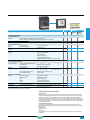
Circuit breakers and switch disconnectors
Measurement and communication
From 100 to 630A
Catalogue
2008
Contents
Introduction
3
Functions
and characteristics
A-1
Installation
recommendations
B-1
Dimensions
and connection
C-1
Wiring diagrams
D-1
Additional
characteristics
E-1
Catalogue numbers
F-1
Glossary
G-1
1
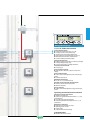
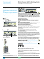
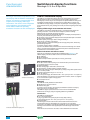
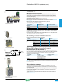
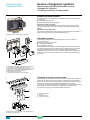
Compact NSX
Next-generation
circuit breakers
Today, next-generation Compact NSX circuit breakers provide an intelligent outlook
and set the standards of tomorrow. A power monitoring unit enhances their
invariably impeccable protective functions. For the first time, users can monitor
both energy and power, offering new performance in a remarkably compact device.
Compactness, discrimination and modularity – all of the features which defined
the success of the Compact NS generation of circuit breakers combined
with new functions for safe, easy monitoring and management of installations.
The new range of Compact NSX circuit breakers stands out from the crowd,
thanks to its electronic intelligence. Through direct access to in-depth information,
and networking via open protocols, Compact NSX lets operators optimise
the management of their electrical installations.
Far more than a circuit breaker, Compact NSX is a measurement
and communication tool ready to meet energy-efficiency needs
through optimised energy consumption, increased energy availability,
and improved installation management.
3
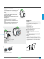
Compact NSX
100-630A
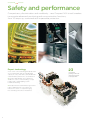
Safety and performance
Compactness, discrimination and modularity – new Compact NSX circuit breakers
incorporate advanced monitoring and communication functions,
from 40 amps up, combined with impeccable protection.
Expert technology
A roto-active contact breaking principle provides
each circuit breaker with very high breaking
capacity in a very small device, remarkable fault
current limitation performance, and endurance.
> Compact NSX benefits from a patented
double roto-active contact breaking concept,
together with a reflex tripping system
for ultimate breaking.
> Exceptional fault current limitation guarantees
robust, reliable protection and, above all,
reduces the causes of component aging,
thus extending service life for installations.
4
23
new patents
pending confirm the
innovative character
of Compact NSX
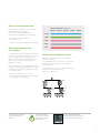
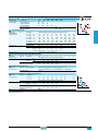
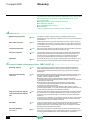
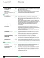
New breaking capacities
Breaking performance at 415 V
New performance levels for Compact NSX
improve application targeting:
> 36-50 kA – standard applications
(industrial plants, buildings and hospitals),
NSX 100
NSX 160
NSX 250
NSX 400
NSX 630
L 150kA
S 100kA
> 70-100 kA – high performance
at controlled cost,
H 70kA
> 150 kA – demanding applications (maritime).
N 50kA
F 36kA
Enhanced protection
for motors
Compact NSX meets the requirements of IEC
60947-4-1 standards for protection of motors:
> well adapted to motor-starting solutions
up to 315 kW at 400 V, providing protection
against short circuits, overloads, phase
unbalance and loss,
> also enables set-up of additional protection
systems for starting and braking with the motor
running, reverse braking, jogging or reversing
in complete safety,
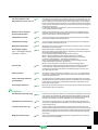
Reduced installation costs
Optimising installations allows for achieving
up to 30% savings:
> considerable savings at the time of installation,
thanks to total discrimination with miniature
circuit breakers,
> smaller devices, more economic switchboards
mean best overall installation cost,
without overcalibration.
> add a Schneider Electric contactor;
Compact NSX complies with the requirements
of so-called type 2 coordination.
NS400
NSX250
NS160
(100 A)
NSX100
Multi 9
The trip units are now true
circuit breaker control
systems.
With the integration
of electronics, trip units
have gained in speed
and accuracy.
Greater reliability and better
discrimination allows more refined
settings, especially for time delays.
5
Compact NSX
100-630A
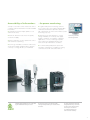
Monitoring and management
Compact NSX is a single device, which contains a monitoring unit
to control energy consumption and power.
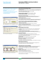
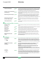
Integrated monitoring
> The new Compact NSX range incorporates
Micrologic electronic trip units in the circuit
breaker, offering both:
Ê UÊ>Ê>VVÕÀ>ÌiÊ«ÜiÀÊÌÀ}ÊÕÌ]
Ê UÊ>Ê
}
ÞÊÀi>LiÊ«ÀÌiVÌÛiÊ`iÛVi°
> A Micrologic electronic tripping device
combines next-generation sensors:
Ê UÊ>ʸÀ¸ÊÃiÃÀÊvÀÊÌ
iÊ«ÜiÀÊÃÕ««Þ
to the electronics,
Ê UÊ>ʸ>À¸ÊÃiÃÀÊ,}ÜÃÊVî
for measurement, guaranteeing
high accuracy.
> These electronic systems are designed
to withstand high temperatures (105°C),
ensuring reliability under severe operating
conditions.
> The originality lies in how Compact NSX
measures, processes and displays data,
either directly on screen, on the switchboard
front panel, or via a monitoring system.
6
10%
Monitoring consumption
can reduce energy costs
by as much as 10%.
Accessibility of information…
To keep costs under control and ensure service
continuity, relevant information must be available
in real time:
> a kilowatt-hour meter helps optimise costs
and their allocation,
> harmonic distortion rate shows the quality
of electrical supply,
> alarm notification secures operational control
and maintenance planning,
> event logs and tables, activated continuously,
ensure the installed equipment base operates
correctly, so energy efficiency is maximized.
Measurement functions are controlled
by an additional microprocessor.
ASIC
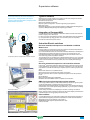
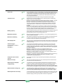
…for power monitoring
> Together with power monitoring software
(e.g., PowerLogic), the Compact NSX Modbus
communication interface provides operators
with a parameter set and tools that make system
monitoring very easy.
> Operators have real-time data to control
Monitoring software
PowerLogic ION-E
energy availability, to monitor power supply
quality, to optimise consumption of different
applications or zones, reducing load peaks
and continuously supplying priority loads,
and to draw up maintenance schedules.
> ÊÃvÌÜ>ÀiÊÕÌÌÞÊ,-1®Ê>ÜÃÊ«ÀÌiVÌÊ
and alarm configuration, in addition to testing
communications with all installed devices.
Protection functions are electronically
managed independently of measurement
functions.
An ASIC (Application-Specific
Integrated Circuit) is common
to all trip units, which boosts
immunity to conducted
or radiated interference
and increases reliability.
7
Compact NSX
100-630A
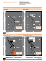
Simplicity
Compact NSX takes the principles of easy installation and use –
which made its predecessor so successful – to a higher level.
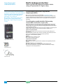
Simple in design
Compact NSX is mounted and wired reusing
the same measurements as Compact NS.
Cut-outs are the same whatever the type
of handle. Engineering drawings are the same,
so installation and connection layouts can be
used on new projects, simplifying extensions
or retrofits, and reducing maintenance costs.
Integration in help software, for parameter
settings and switchboard installation,
further eases design.
Simple to install
> A transparent lead-sealable cover protects
access to tripping device switches and prevents
settings from being changed.
> The new electrical control adjustment also has
a transparent lead- sealable cover to prevent it
from being operated accidentally.
> Compact NSX has an optional functional
terminal shield that offers excellent protection
against direct contact (IP40 on all sides,
IP20 at cable entry points) and easy installation.
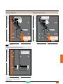
> All Compact NSX devices can be equipped
with a communication function via a pre-wired
connection with a Modbus interface module.
When the Modbus address is declared,
the Compact NSX device is integrated
into the network.
8
> There are four levels of functionalities:
Ê
Ê
Ê
Ê
Ê
UÊVÕV>ÌÊvÊ`iÛViÊÃÌ>ÌÕÃ\
On/Off position, trip indication
and fault-trip indication,
UÊVÕV>ÌÊvÊV>`Ã\
open, close, and reset,
UÊVÕV>ÌÊvÊi>ÃÕÀiiÌÃ\
Ê >ÞÊ]Ê1]Êv]Ê*]Ê]Ê>`Ê/]
UÊVÕV>ÌÊvÊ«iÀ>Ì}Ê>ÃÃÃÌ>Vi
data: settings, parameters, alarms,
histograms and event tables,
and maintenance indicators.
> /
iÊÃÜÌV
L>À`ʸ«Õ}ÊEÊ«>Þ¸Ê`ë>ÞÊÕÌÊ
connects to the trip unit without any special
settings or configuration. A cable fitted
ÜÌ
Ê>Ê,{xÊViVÌÀÊ>ÜÃÊvÀÊi>ÃÞÊ
integration with communications networking.
Simple to use
> 1ÃiÀÃÊVÕÃÌÃiÊÌiÃÌ>«i`Ê>>ÀÃ
for all parameters, assign them to indicator
lights, choose display priorities, and configure
time delay thresholds and modes.
> Event logs and tables are continuouslyactivated. Providing a wealth of information,
they enable users to ensure that the installed
equipment base operates correctly, to optimize
settings, and to maximise energy efficiency.
> Local and remote displays offer easy access
to operators and provide the main electrical
Û>ÕiÃ\Ê]Ê1]Ê6]Êv]ÊiiÀ}Þ]Ê«ÜiÀ]ÊÌÌ>Ê
>ÀVÊ
distortion, etc. The user-friendly switchboard
display unit with intuitive navigation is more
comfortable to read, and offers quick access
to information.
Performance,
yet unimposing.
Compact NSX perfectly
blends into
its environment.
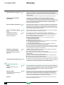
Attractively designed.
The front of Compact NSX circuit breakers has an attractive
curved profile.
Measurements are easy to read on a backlit LCD display.
Screen navigation is intuitive and settings are simplified
by immediate readouts in amps.
9
Compact NSX
100-630A
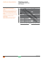
Service continuity
Compact NSX makes discrimination its main advantage in minimising the impact
of short circuits, ensuring service continuity for installations.
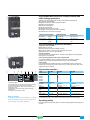
Total discrimination
Thanks to its 30 years of experience,
Schneider Electric, with Compact NSX,
offers perfect mastery of discrimination
for ever more reliable service continuity.
Compact NSX circuit breakers strongly limit
fault currents, occurring as the result
of short-circuits, which reduces installation
downtime and avoids over-dimensioning cables.
When several circuit breakers are used in series,
the downstream circuit breaker trips as close
as possible to the fault, isolating only the circuit
concerned. The upstream circuit breaker
is not affected and allows the other circuits
to remain operational.
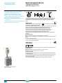
Service continuity
``}Ê>Ê-/Ê`ÕiÊ>ÜÃÊÀiÌiÊ
indication of motor overloads and actuation
of a contactor, ensuring total service continuity:
> Ì
iÊ-/ÊÃÜÌV
iÃÊÌ
iÊVÌ>VÌÀÊÃÌi>`
of tripping the circuit breaker,
> the module allows for machine restart directly
from the contactor without having to operate
circuit breakers.
Preventive maintenance
Maintenance indicators provide information
on the number of operations, level of wear
on contacts and total load rates. This makes it
far easier to monitor equipment ageing
and optimise investments over time.
Maintenance is now preventive, avoiding faults.
10
100%
service continuity
Direct access
to maintenance
indicators
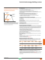
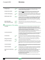
Schneider Electric
expertise
Schneider Electric commits to reducing energy costs and CO2 emissions
for its customers. It offers products, solutions and services that integrate
with all levels of the energy value chain. Compact NSX is part and parcel
of the Schneider Electric energy efficiency approach.
Solutions for the future
With Compact NSX, Schneider Electric works
through flexible solutions for commercial
and industrial buildings, Schneider Electric
commits to help customers gradually move
towards an active approach to their energy
efficiency. It helps get more return from
investments and future design solutions.
Energy performance
contracts
30%
Up to
savings in energy costs
4 steps
> Diagnostics
> Proposals
> Implementation
> Follow-up
An energy performance contract offers
innovative service to modernise technical
installations.
The objective is dramatically to reduce energy
costs, whilst improving comfort and safety,
all in an environmentally-responsible way.
Environmentally responsible
Schneider Electric meets the expectations
of its markets with products adapted
to the practices of the 190 countries where it
is present and strongly commits to respect the
norms and directives of each of those countries.
Ê UÊ
«>VÌÊ -8]ÊiÊ>ÊÌ
iÊ«À`ÕVÌÃ
in its LV ranges, is a product designed
to comply with all European directives
for the environment. It has also received
international certifications and approval
from independent agencies.
Ê UÊÊV«>ViÊÜÌ
Ê-"Ê£{ää£ÊÃÌ>`>À`Ã]
all of its factories are nonpolluting.
Ê UÊiÃ}i`ÊvÀÊi>ÃÞÊ`Ã>ÃÃiLÞ
and recycling at end of life, Compact NSX
complies with environmental directives
Ê Ê ,-IÊ>`Ê7II°ÊÊ Ê
IÊ,-ÊrÊ,iÃÌÀVÌÊvÊ>â>À`ÕÃÊ-ÕLÃÌ>ViÃ
IIÊ7ÊrÊ7>ÃÌiÊiVÌÀV>Ê>`ÊiVÌÀVʵիiÌ
11
Protection, measurement
and communication...
Compact NSX
Functions and characteristics
Introduction
Overview of applications
General characteristics of the Compact NSX range
Characteristics and performance of Compact NSX circuit breakers
from 100 to 630 A
Compact NSX trip units
Overview of trip units for Compact NSX
A-2
A-4
A-6
A-8
A-10
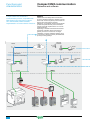
Protection of distribution systems
TM thermal-magnetic and MA magnetic trip units
Micrologic 2 and 1.3-M trip units
Micrologic 5 / 6 A or E trip units
A-14
A-16
A-18
Power Meter functions
Electronic Micrologic 5 / 6 A or E
A-20
Operating-assistance functions
Micrologic 5 / 6 A or E trip units
A-22
Switchboard-display functions
Micrologic 5 / 6 A or E trip units
A-24
Compact NSX communication
Communications modules
Networks and software
RSU and RCU utilities
Supervision software
A-26
A-28
A-30
A-31
Accessories for Micrologic trip units
A-32
Earth-leakage protection
Add-on protection against insulation faults using a Vigi module or Vigirex relay A-34
Motor protection
General information on motor feeders
Motor-feeder characteristics and solutions
Compact NSX motor-feeder solutions
MA and Micrologic 1.3-M instantaneous trip units
Micrologic 2-M electronic trip units
Micrologic 6 E-M electronic trip units
A-36
A-38
A-39
A-40
A-42
A-44
Special applications
Generator protection with Micrologic 2.2-G
Protection of industrial control panels
16 Hz 2/3 network protection
Micrologic 5 A-Z trip unit
Protection of 400 Hz systems
A-48
A-50
A-51
A-51
A-52
Switch-disconnectors
Overview of applications
Switch-disconnector functions
Characteristics and performance of Compact NSX switch-disconnectors
from 100 to 630 NA
A-54
A-55
A-56
Source-changeover systems
Presentation
Manual source-changeover systems
Remote-operated and automatic source-changeover systems
Coupling accessory on base plate
A-58
A-59
A-60
Accessories and auxiliaries
Installation recommendations
Dimensions and connection
Wiring diagrams
Additional characteristics
Catalogue numbers
Glossary
559E1000.indd
B-1
C-1
D-1
E-1
F-1
G-1
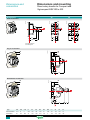
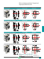
Overview of Compact NSX100 to 630 fixed version
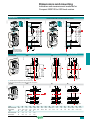
Overview of Compact NSX100 to 630 plug-in and withdrawable versions
Device installation
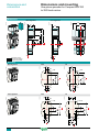
Connection of fixed devices
Connection of withdrawable and plug-in devices
Insulation of live parts
Selection of auxiliaries for Compact NSX100/160/250
Selection of auxiliaries for Compact NSX400/630
Connection of electrical auxiliaries
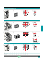
Indication contacts
SDx and SDTAM modules for Micrologic
Motor mechanism
Remote tripping
Rotary handles
Additional measurement and indication modules
Locks
Sealing accessories
Individual enclosures
Escutcheons and protection collars
version: 1.0
A-62
A-64
A-66
A-78
A-70
A-71
A-72
A-74
A-76
A-78
A-79
A-80
A-81
A-82
A-84
A-86
A-87
A-88
A-89
A-1
Functions and
characteristics
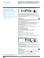
Introduction
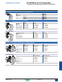
Overview of applications
Functions
Applications
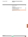
DB112087
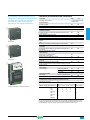
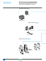
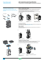
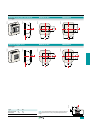
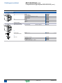
Compact NSX100 to 630 offers high
performance and a wide range of
interchangeable trip units to protect most
applications. Electronic versions provide
highly accurate protection with wide setting
ranges and can integrate measurement,
metering and communication functions.
They can be combined with the FDM121
switchboard display unit to provide all the
functions of a Power Meter as well as
operating assistance.
DB112086
DB112088
G
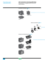
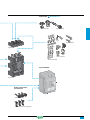
Compact NSX equipped with Micrologic
5 / 6 trip units offer type A (ammeter) or E
(energy) metering functions as well as
communication. Using Micrologic
sensors and intelligence, Compact NSX
provides access to measurements of all
the main electrical parameters on the
built-in screen, on a dedicated FDM121
display unit or via the communication
system.
DB112089
Power Meter
page A-20
Operating assistance
page A-22
Switchboard display unit
page A-24
DB112090
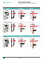
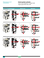
Integration of measurement functions
provides operators with operating
assistance functions including alarms
tripped by user-selected measurement
values, time-stamped event tables and
histories, and maintenance indicators.
Communication
page A-26
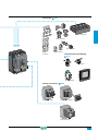
Compact NSX equipped with Micrologic
5 / 6 trip units provide communication
capabilities. Simple RJ45 cords connect
to a Modbus interface module.
A-2
version: 1.0
DB112091
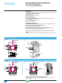
The main measurements can be read on
the built-in screen of Micrologic 5 / 6 trip
units.
They can also be displayed on the
FDM121 switchboard display unit along
with pop-up windows signalling the main
alarms.
559E1100.indd
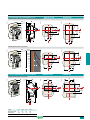
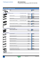
Protection of
distribution
systems
(AC 220/690 V)
page A-14
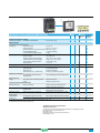
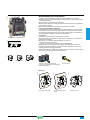
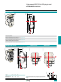
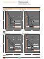
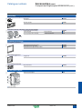
Compact NSX devices are equipped with MA or TM
thermal-magnetic trip units or Micrologic 2 / 5 / 6
electronic trip units to provide protection against shortcircuits and overloads for:
b distribution systems supplied by transformers
b distribution systems supplied by engine generator
sets
b long cables in IT and TN systems.
They can be easily installed at all levels in distribution
systems, from the main LV switchboard to the
subdistribution boards and enclosures.
All Compact NSX devices can protect against
insulation faults by adding a Vigi module or Vigirex
relay.
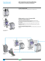
Protection of
motors
(AC 220/690 V)
page A-36
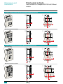
The Compact NSX range includes a number of
versions to protect motor applications:
b basic short-circuit protection with MA magnetic trip
units or the electronic Micrologic 1-M version,
combined with an external relay to provide thermal
protection
b protection against overloads, short-circuits and
phase unbalance or loss with Micrologic 2-M trip units
b more complete protection against overloads and
short-circuits with additional motor-specific protection
(phase unbalance, locked rotor, underload and long
start) with Micrologic 6 E-M trip units. These versions
also offer communication, metering and operating
assistance.
The exceptional limiting capacity of Compact NSX
circuit breakers automatically provides type-2
coordination with the motor starter, in compliance with
standard IEC 60947-4-1.
Protection of
special
applications
page A-48
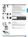
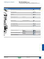
Special applications :
The Compact NSX range offers a number of versions
for special protection applications:
b service connection to public distribution systems
page A-48
b generators
s page A-50
b industrial control panels
s page A-52
with:
v compliance with international standards
IEC 60947-2 and UL 508 / CSA 22-2 N14
v compliance with US standard UL 489
v installation in universal and functional enclosures.
s page A-53
b 16 Hz 2/3 systems
b 400 Hz systems
s page A-54
For all these applications, circuit breakers in the
Compact NSX range offer positive contact indication
and are suitable for isolation in accordance with
standards IEC 60947-1 and 2.
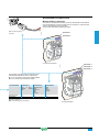
Control and
isolation using
switchdisconnectors
page A-56
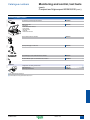
A switch-disconnector version of Compact NSX circuit
breakers is available for circuit control and isolation.
All add-on functions of Compact NSX circuit breakers
may be combined with the basic switch-disconnector
function, including:
b earth-leakage protection
b motor mechanism
b ammeter, etc.
For information on other switch-disconnector ranges,
see the Interpact (offering positive contact indication
and visible break) and Fupact (fusegear) catalogues.
Source
changeover
systems
page A-60
To ensure a continuous supply of power, some
electrical installations are connected to two power
sources:
b a normal source
b a replacement source to supply the installation when
the normal source is not available.
A mechanical and/or electrical interlocking system
between two circuit breakers or switch-disconnectors
avoids all risk of parallel connection of the sources
during switching.
A source-changeover system can be:
b manual with mechanical device interlocking
b remote controlled with mechanical and/or electrical
device interlocking
b automatic by adding a controller to manage
switching from one source to the other on the basis of
external parameters.
559E1100.indd
version: 1.0
A-3
Functions and
characteristics
Introduction
General characteristics of the Compact NSX
range
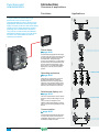
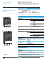
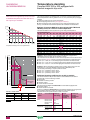
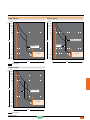
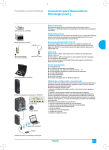
DB112018
Compliance with standards
1
2
3
NSX250 H
100
70
65
50
35
10
100
70
65
50
35
10
4
5
6
7
100
65
35
8
9
10
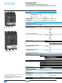
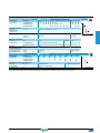
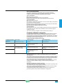
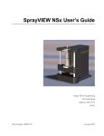
Standardised characteristics indicated on the rating plate:
1 Type of device: frame size and breaking capacity class
2 Ui: rated insulation voltage.
3 Uimp: rated impulse withstand voltage.
4 Ics: service breaking capacity.
5 Icu: ultimate breaking capacity for various values of the
rated operational voltage Ue
6 Ue: operational voltage.
7 Colour label indicating the breaking capacity class.
8 Circuit breaker-disconnector symbol.
9 Reference standard.
10 Main standards with which the device complies.
Note: when the circuit breaker is equipped with an extended
rotary handle, the door must be opened to access the rating
plate.
Compact NSX circuit breakers and auxiliaries comply with the following:
b international recommendations:
v IEC 60947-1: general rules
v IEC 60947-2: circuit breakers
v IEC 60947-3: switch-disconnectors
v IEC 60947-4: contactors and motor starters
v IEC 60947-5.1 and following: control circuit devices and switching elements;
automatic control components
b European (EN 60947-1 and EN 60947-2) and corresponding national standards:
v France NF
v Germany VDE
v United Kingdom BS
v Australia AS
v Italy CEI
b the specifications of the marine classification companies (Veritas, Lloyd's Register
of Shipping, Det Norske Veritas, etc.), standard NF C 79-130 and recommendations
issued by the CNOMO organisation for the protection of machine tools.
For U.S. UL, Canadian CSA, Mexican NOM and Japanese JIS standards, please
consult us.
Pollution degree
Compact NSX circuit breakers are certified for operation in pollution-degree III
environments as defined by IEC standards 60947-1 and 60664-1 (industrial
environments).
Climatic withstand
Compact NSX circuit breakers have successfully passed the tests defined by the
following standards for extreme atmospheric conditions:
b IEC 60068-2-1: dry cold (-55 °C)
b IEC 60068-2-2: dry heat (+85 °C)
b IEC 60068-2-30: damp heat (95 % relative humidity at 55 °C)
b IEC 60068-2-52 severity level 2: salt mist.
Environment
Compact NSX respects the European environment directive EC/2002/95 concerning
the restriction of hazardous substances (RoHS).
Product environment profiles (PEP) have been prepared, describing the
environmental impact of every product throughout its life cycle, from production to
the end of its service life.
All Compact NSX production sites have set up an environmental management
system certified ISO 14001.
Each factory monitors the impact of its production processes. Every effort is made to
prevent pollution and to reduce consumption of natural resources.
Ambient temperature
b Compact NSX circuit breakers may be used between -25 °C and +70 °C. For
temperatures higher than 40°C (65°C for circuit breakers used to protect motor
feeders), devices must be derated (pages B-8 and B-9).
b Circuit breakers should be put into service under normal ambient, operatingtemperature conditions. Exceptionally, the circuit breaker may be put into service
when the ambient temperature is between -35 °C and -25 °C.
b The permissible storage-temperature range for Compact NSX circuit breakers in
the original packing is -50 °C (1) and +85 °C.
(1) -40 °C for Micrologic control units with an LCD screen.
A-4
version: 1.0
559E1100.indd
Electromagnetic compatibility
Compact NSX devices are protected against:
b overvoltages caused by circuit switching (e.g. lighting circuits)
b overvoltages caused by atmospheric disturbances
b devices emitting radio waves such as mobile telephones, radios, walkie-talkies,
radar, etc.
b electrostatic discharges produced by users.
Immunity levels for Compact NSX comply with the standards below.
b IEC/EN 60947-2: Low-voltage switchgear and controlgear, part 2: Circuit
breakers:
v Annex F: Immunity tests for circuit breakers with electronic protection
v Annex B: Immunity tests for residual current protection
b IEC/EN 61000-4-2: Electrostatic-discharge immunity tests
b IEC/EN 61000-4-3: Radiated, radio-frequency, electromagnetic-field immunity
tests
b IEC/EN 61000-4-4: Electrical fast transient/burst immunity tests
b IEC/EN 61000-4-5: Surge immunity tests
b IEC/EN 61000-4-6: Immunity tests for conducted disturbances induced by radiofrequency fields
b CISPR 11: Limits and methods of measurement of electromagnetic disturbance
characteristics of industrial, scientific and medical (ISM) radio-frequency equipment.
Discrimination
Compact NSX reinforces the discrimination capabilities of the Compact NS range by
applying the rapid calculation capacity of the Micrologic trip units.
Total discrimination is now possible between NSX100 and modular Multi 9 circuit
breakers rated y 63 A (see page A-8).
PB103578-53
Suitable for isolation with positive contact
indication
DB112093
All Compact NSX circuit breakers are suitable for isolation as defined in IEC
standard 60947-2:
b The isolation position corresponds to the O (OFF) position.
b The operating handle cannot indicate the OFF position unless the contacts are
effectively open.
b Padlocks may not be installed unless the contacts are open.
Installation of a rotary handle or a motor mechanism does not alter the reliability of
the position-indication system.
The isolation function is certified by tests guaranteeing:
b the mechanical reliability of the position-indication system
b the absence of leakage currents
b overvoltage withstand capacity between upstream and downstream connections.
The tripped position does not insure isolation with positive contact indication.
Only the OFF position guarantees isolation.
Installation in class II switchboards
All Compact NSX circuit breakers are class II front face devices. They may be
installed through the door of class II switchboards (as per IEC standards 61140 and
60664-1) without downgrading switchboard insulation. Installation requires no
special operations, even when the circuit breaker is equipped with a rotary handle or
a motor mechanism.
Degree of protection
The following indications are in accordance with standards IEC 60529 (IP degree of
protection) and IEC 62262 (IK protection against external mechanical impacts).
Bare circuit breaker with terminal shields
b With toggle: IP40, IK07.
b With standard direct rotary handle / VDE: IP40 IK07
Circuit breaker installed in a switchboard
b With toggle: IP40, IK07.
b With direct rotary handle:
v standard / VDE: IP40, IK07
v MCC: IP43 IK07
v CNOMO: IP54 IK08
b With extended rotary handle: IP56 IK08
b With motor mechanism: IP40 IK07.
559E1100.indd
version: 1.0
A-5
PB103354-40
Functions and
characteristics
Introduction
Characteristics and performance of
Compact NSX circuit breakers from 100 to 630 A
Common characteristics
Rated voltages
Insulation voltage (V)
Ui
800
Impulse withstand voltage
(kV)
Uimp
8
Operational voltage (V)
Ue
Suitability for isolation
AC 50/60 Hz
690
IEC/EN 60947-2
yes
Utilisation category
A
Pollution degree
IEC 60664-1
3
Circuit breakers
Breaking capacity levels
Electrical characteristics as per IEC 60947-2
Rated current (A)
40 °C
lcu
AC 50/60 Hz 220/240 V
380/415 V
440 V
500 V
525 V
660/690 V
lcs
AC 50/60 Hz 220/240 V
380/415 V
440 V
500 V
525 V
660/690 V
Mechanical
Electrical
440 V
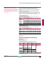
PB103279-44
Compact NSX100/160/250.
In
Number of poles
Breaking capacity (kA rms)
Service breaking capacity (kA rms)
Durability (C-O cycles)
690 V
In/2
In
In/2
In
Characteristics as per Nema AB1
Breaking capacity (kA rms)
AC 50/60 Hz 240 V
480 V
600 V
Characteristics as per UL 508
Breaking capacity (kA rms)
AC 50/60 Hz 240 V
480 V
600 V
Compact NSX400/630.
Protection and measurements
Short-circuit protection
Overload / short-circuit protection
Magnetic only
Thermal magnetic
Electronic
with neutral protection (Off-0.5-1-OSN) (1)
with ground-fault protection
with zone selective
interlocking (ZSI) (2)
Display / I, U, f, P, E, THD measurements / interrupted-current measurement
Options
Power Meter display on door
Operating assistance
Counters
Histories and alarms
Metering Com
Device status/control Com
Earth-leakage protection
By Vigi module
By Vigirex relay
Installation / connections
Dimensions and weights
(1) OSN: Over Sized Neutral protection for neutrals carrying
high currents (e.g. 3rd harmonics).
(2) ZSI: Zone Selective Interlocking using pilot wires.
(3) 2P circuit breaker in 3P case for B and F types, only with
thermal-magnetic trip unit.
A-6
Dimensions (mm)
WxHxD
Fixed, front connections
Weight (kg)
Fixed, front connections
2/3P
4P
2/3P
4P
Connections
Connection terminals
Pitch
With/without spreaders
Large Cu or Al cables
Cross-section
mm²
version: 1.0
559E1100.indd
Common characteristics
Control
Manual
Electrical
With toggle
b
With direct or extended rotary handle
b
With remote control
b
Versions
b
Fixed
Withdrawable
NSX100
F
N
H
Plug-in base
b
Chassis
b
NSX160
S
L
F
N
H
NSX250
S
L
F
N
H
NSX400
S
L
N
H
S
NSX630
L
N
100
160
250
400
630
2 (3), 3, 4
2 (3), 3, 4
2 (3), 3, 4
3, 4
3, 4
85
36
35
25
22
8
H
S
L
90
50
50
36
35
10
100
70
65
50
35
10
120
100
90
65
40
15
150
150
130
70
50
20
85
36
35
30
22
8
90
50
50
36
35
10
100
70
65
50
35
10
120
100
90
65
40
15
150
150
130
70
50
20
85
36
35
30
22
8
90
50
50
36
35
10
100
70
65
50
35
10
120
100
90
65
40
15
150
150
130
70
50
20
85
50
42
30
22
10
100
70
65
50
35
20
120
100
90
65
40
25
150
150
130
70
50
35
85
50
42
30
22
10
100
70
65
50
35
20
120
100
90
65
40
25
150
150
130
70
50
35
85 90
36 50
35 50
12.5 36
11
35
4
10
50000
50000
30000
20000
10000
100
70
65
50
35
10
120
100
90
65
40
15
150
150
130
70
50
20
85 90
36 50
35 50
12.5 36
11
35
4
10
40000
10000
20000
15000
7500
100
70
65
50
35
10
120
100
90
65
40
15
150
150
130
70
50
20
85 90
36 50
35 50
30 36
22 35
8
10
20000
20000
10000
10000
5000
100
70
65
50
35
10
120
100
90
65
40
15
150
150
130
70
50
20
85 100
50 70
42 65
30 50
11
11
10 10
15000
12000
6000
6000
3000
120
100
90
65
12
12
150
150
130
70
12
12
85 100
50 70
42 65
30 50
11
11
10 10
15000
8000
4000
6000
2000
120
100
90
65
12
12
150
150
130
70
12
12
40
20
-
85
35
8
90
50
20
100 120 150 40
65 90 130 20
35 40 50 -
85
35
20
90
50
20
100 120 150 40
65 90 130 20
35 40 50 -
85
35
20
90
50
20
100 120 150 40
65 90 130 30
35 40 50 -
85
42
20
100 120 150 40
65 90 130 30
35 40 50 -
85
42
20
100 120 150
65 90 130
35 40 50
-
85
25
10
85
50
10
85
65
10
85
35
10
85
50
10
85
65
10
85
35
15
85
50
15
85
65
15
85
50
20
85
65
20
85
50
20
85
65
20
-
-
-
-
-
-
-
-
85
35
20
-
-
85
35
20
b
b
b
b
b
b
b
b
b
b
b
b
b
b
b
b
b
b
b
b
b
b
b
b
b
b
b
b
b
b
b
b
b
b
b
b
b
b
b
b
b
b
b
b
b
b
b
b
b
b
b
b
b
b
b
b
b
b
b
b
b
b
b
b
b
b
b
b
b
b
b
b
b
105 x 161 x 86
140 x 161 x 86
2.05
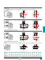
2.4
105 x 161 x 86
140 x 161 x 86
2.2
2.6
105 x 161 x 86
140 x 161 x 86
2.4
2.8
140 x 225 x 110
185 x 255 x 110
6.05
7.90
140 x 225 x 110
185 x 255 x 110
6.2
8.13
35/45 mm
35/45 mm
35/45 mm
300
300
300
45/52.5 mm
45/70 mm
4 x 240
45/52.5 mm
45/70 mm
4 x 240
559E1100.indd
version: 1.0
-
-
A-7
Functions and
characteristics
Introduction
With Micrologic electronic trip units,
Compact NSX stands out from the crowd.
Thanks to the new generation of sensors
and its processing capability, protection is
enhanced even further. It also provides
measurements and operating information.
Thermal-magnetic or electronic trip unit?
Compact NSX trip units
Thermal-magnetic trip units protect against overcurrents and short-circuits using
tried and true techniques. But today, installation optimisation and energy efficiency
have become decisive factors and electronic trip units offering more advanced
protection functions combined with measurements are better suited to these needs.
Micrologic electronic trip units combine reflex tripping and intelligent operation.
Thanks to digital electronics, trip units have become faster as well as more accurate
and reliable. Wide setting ranges make installation upgrades easier. Designed with
processing capabilities, Micrologic trip units can provide measurement information
and device operating assistance. With this information, users can avoid or deal more
effectively with disturbances and can play a more active role in system operation.
They can manage the installation, anticipate on events and plan any necessary
servicing.
Accurate measurements for complete protection
Compact NSX devices take advantage of the vast experience acquired since the
launch of Masterpact NW circuit breakers equipped with Micrologic trip units.
From 40 amperes on up to the short-circuit currents, they offer excellent
measurement accuracy. This is made possible by a new generation of current
transformers combining "iron-core" sensors for self-powered electronics and "aircore" sensors (Rogowski toroids) for measurements.
The protection functions are managed by an ASIC component that is independent of
the measurement functions. This independence ensures immunity to conducted and
radiated disturbances and a high level of reliability.
Numerous security functions
Torque-limiting screws
The screws secure the trip unit to the circuit breaker. When the correct tightening
torque is reached, the screw heads break off. Optimum tightening avoids any risk of
temperature rise. A torque wrench is no longer required.
Easy and sure changing of trip units
All trip units are interchangeable, without wiring. A mechanical mismatch-protection
system makes it impossible to mount a trip unit on a circuit breaker with a lower
rating.
"Ready" LED for a continuous self-test
The LED on the front of the electronic trip units indicates the result of the self-test
runs continuously on the measurement system and the tripping release. As long as
the green LED is flashing, the links between the CTs, the processing electronics and
the Mitop release are operational. The circuit breaker is ready to protect. No need for
a test kit. A minimum current of 15 to 50 A, depending on the device, is required for
this indication function.
A patented dual adjustment system for protection functions.
Available on Micrologic 5 / 6, the system consists of:
b a first adjustment, under de-energised conditions and using a dial, sets the
maximum value
b a second adjustment, made via the keypad or remotely, fine-tunes the setting.
The second setting may not exceed the first. It can be read directly on the Micrologic
screen, to within one ampere and a fraction of a second.
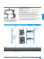
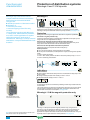
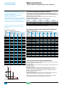
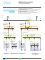
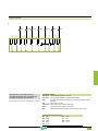
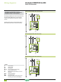
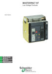
Coordinated tripping systems
Currents
Time delay
Protection
function
Ir
100 A
L
1 - 200 s
Overload:
Slow trip inversely
proportional to
the current level
Ii
Isd
1000 A
z
E.g. NSX100F
S or S0
20 - 500 ms
Short time:
Impedant short-circuit,
instantaneous trip with
adjustable S or fixed
S0 time delay
1500 A
I
10 - 50 ms
Instantaneous:
Ultra-fast detection
with micro delay
for discrimination
Reflex threshold
z
DB115565
Compact NSX detects faults even faster and its tripping time is reduced. It protects
the installation better and limits contact wear.
2400 A
Icu
36000 A
< 5 ms
Reflex:
Energy-based ultra-fast
detection with major current
limiting (1)
(1) This tripping system is completely independent of the trip unit.
Because it directly actuates the mechanism, it precedes the trip unit by a few milliseconds.
A-8
version: 1.0
559E1100.indd
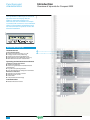
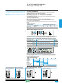
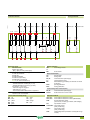
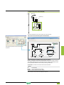
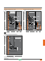
DB111354
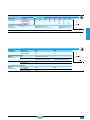
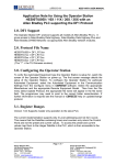
Unmatched discrimination
NS400
NSX250
NS160
(100 A)
NSX100
Discrimination
Compact NSX provides maximum continuity of service and savings through an
unmatched level of discrimination:
b given the high accuracy of measurements, overload discrimination is ensured
even between very close ratings
b for major faults, the fast processing of the Micrologic trip units means the
upstream device can anticipate the reaction of the downstream device. The
upstream breaker adjusts its tripping delay to provide discrimination
b for very high faults, the energy of the arc dissipated by the short-circuit in the
downstream breaker causes reflex tripping. The current seen by the upstream
device is significantly limited. The energy is not sufficient to cause tripping, so
discrimination is maintained whatever the short-circuit current.
Multi 9
Compact NSX100 with Micrologic for total discrimination.*
Better coordination between protection functions reduces the
difference in ratings required for total discrimination.
* Please refer to supplementary technical catalogue.
For total discrimination over the entire range of possible faults, from the long-time
pick-up Ir to the ultimate short-circuit current Icu, a ratio of 2.5 must be maintained
between the ratings of the upstream and downstream devices.
This ratio is required to ensure selective reflex tripping for high short-circuits.
Understanding the names of Micrologic electronic trip units
Protection
DB112155
3: NSX400/630
E: Energy
DB112156
5: LSI
A: Ammeter
DB112094
2: NSX100/160/250
2: LS0I
Measurements
DB112120
1: I
Frame
Applications
Distribution, otherwise
G: Generator
M: Motors
6: LSIG
I:
Instantaneous
L: Long time
S0: Short time (1)
(fixed delay)
S:
Short time
G: Ground fault
Examples
Micrologic 1.3
Instantaneous only
400 or 630 A
Micrologic 2.3
LS0I
400 or 630 A
Distribution
Micrologic 5.2 A
LSI
100, 160 or 250 A
Ammeter
Distribution
Micrologic 6.3 E-M
LSIG
400 or 630 A
Energy
Motor
Distribution
(1) LS0I protection is standard on Micrologic 2. To ensure discrimination, it offers short-time protection S0 with a non-adjustable
delay and instantaneous protection.
559E1100.indd
version: 1.0
A-9
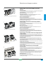
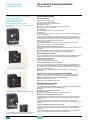
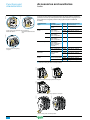
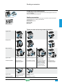
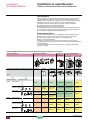
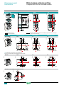
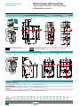
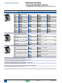
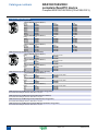
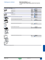
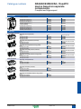
Overview of trip units
for Compact NSX
Type of protection and applications
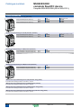
MA magnetic
TM-D thermal-magnetic
DB112029
Compact NSX offers a range of trip units in
interchangeable cases, whether they are
magnetic, thermal-magnetic or electronic.
Versions 5 and 6 of the electronic trip unit
offer communication and metering. Using
Micrologic sensors and intelligence,
Compact NSX supplies all the information
required to manage the electrical installation
and optimise energy use.
Introduction
DB112028
Functions and
characteristics
b Distribution and motors
b Distribution
b Generators
DB112023
DB112094
Compact NSX100/160/250
DB112022
Circuit breakers and trip units
MA Distribution and
motors
DB112092
TM-D Distribution
TM-G Generators
DB112120
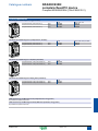
Compact NSX400/630
1.3-M Distribution and
motors
DB112038
DB112037
Settings and indications
Adjustment and
reading
Pick-up set in amps using
dials
Non-adjustable time
delay
A-10
version: 1.0
Adjustment and
reading
Pick-up set in amps using
dials
Non-adjustable time
delay
559E1100.indd
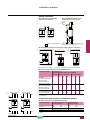
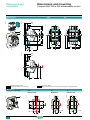
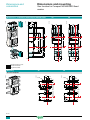
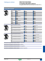
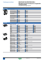
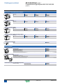
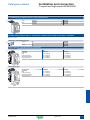
Micrologic 5 / 6 A or E electronic trip units
b Distribution
and generators
b Distribution
and generators
b Motors
DB111401
DB111402
6.2 E-M Motors
>30A
Alarm
6.2 A Distribution
and generators
6.2 E Distribution
and generators
DB112027
5.2 A Distribution
and generators
5.2 E Distribution
and generators
5.2 A-Z 16 Hz 2/3 networks
Ready
2.2 Distribution
2.2-G Generators
2.2-M Motors
DB112025
class
A: current metering functions
E :current and energy metering functions.
DB112026
DB112024
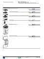
b Distribution
b Service connection (public
distribution)
b Generators
b Motors (I only)
b Motors
6 E-M
DB112033
6 A or E
DB112032
DB112030
5 A or E
DB115635
Micrologic 2 electronic
350
320
280
250
Ir (A)
400
440
470
500
.4
.5 .6 .7
.8
.3
.9
.2
Micrologic 6.3 E-M
>95
% T°
380
OFF
Ir Cl.
Isd
Iunbal tunbal Ijam tjam Ig
500
N
Mode
1/A
2/B 3/C
tg
Ii=6500A
A
IEC60947-4-1
Class
test
OK
Ir 7.2Ir Isd
Ig (x In)
6.3 A Distribution
and generators
6.3 E Distribution
and generators
DB111366
5.3 A Distribution
and generators
5.3 E Distribution
and generators
5.3 A-Z 16 Hz 2/3 networks
DB112041
DB112039
2.3 Distribution
1.3-M Motors (I only)
2.3-M Motors
Alarm History
DB112019
07 May 2007
Time:
10:28:03.01 PM
OK
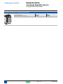
Connection to switchboard
display unit
DB111367
DB112042
Adjustment and reading
Pick-up set in amps
2/3
Total reactive
Power
Date:
ESC
Adjustment and reading
Pick-up set in amps with fine
adjustment using dials
Non-adjustable time delay
6.3 E-M Motors
DB112040
Front indications
DB112043
Fine adjustment via
keypad
0.5
Adjustable time delays
Communication to Modbus
DB112019
Test connector
Self test
DB112040
Front indications
Test connector
Self test
559E1100.indd
version: 1.0
A-11
Functions and
characteristics
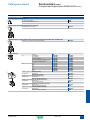
DB112526
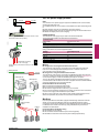
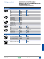
Overview of trip units for Compact NSX
DB112044
The capabilities of Micrologic 5 / 6 A and E
trip units come into full play with the
FDM121 switchboard display unit.
When the two are connected via a simple
cord with RJ45 connectors, the combination
offers full Power Meter capabilities and all
the measurements required to monitor the
electrical installation.
Introduction
Ammeter Micrologic (A)
I measurements
Current measurements
b Phase and neutral currents I1, I2, I3, IN
b Average current of the 3 phases Iavg
b Highest current of the three phases Imax
b Ground-fault current Ig (Micrologic 6.2 / 6.3 A)
b Maximeter/minimeter for I measurements
Operating and maintenance assistance
Indications, alarms and histories
b Indication of fault types
b Alarms for high/low alarm thresholds linked to I
measurements
b Trip, alarm and operating histories
b Time-stamped tables for settings and maximeters
Maintenance indicators
b Operation, trip and alarm counters
b Operating hours counter
b Contact wear
b Load profile and thermal image
Communication
b Modbus with add-on module
A-12
version: 1.0
559E1100.indd
DB112045
Energy Micrologic (E)
I, U, f, P, E, THD measurements
Current measurements
b Phase and neutral currents I1, I2, I3, IN
b Average current of the 3 phases Iavg
b Highest current of the three phases Imax
b Ground-fault current Ig (Micrologic 6.2 / 6.3 A)
b Maximeter/minimeter for I measurements
b Current unbalance between phases
Voltage measurements
b Phase-to-phase (U) et phase-to-neutral (V) voltages
b Average voltages Uavg, Vavg
b Ph-Ph (U) and Ph-N (V) voltage unbalance
Frequency measurements
b Frequency (f)
Power-quality indicators
b Total harmonic distortion (THD) for current and
voltage
Power measurements
b Active, reactive and apparent power, total and per
phase
b Power factor and cos
Maximeters/minimeters
b For all I, U, f, P, E measurements
Demand current and power measurements
b Demand values, total and per phase
b Maximum demand
Energy metering
b Active, reactive and apparent energy, total and per
phase
Operating and maintenance assistance
Indications, alarms and histories
b Indication of fault types
b Alarms for high/low thresholds linked to I, U, f, P, E
measurements
b Trip, alarm and operating histories
b Time-stamped tables for settings and I, U, f, P, E
maximeters
Maintenance indicators
b Operation, trip and alarm counters
b Operating hours counter
b Contact wear
b Load profile and thermal image
Communication
b Modbus with add-on module
559E1100.indd
version: 1.0
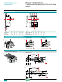
A-13
Functions and
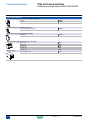
characteristics
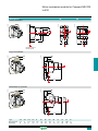
Protection of distribution systems
TM thermal-magnetic and MA magnetic trip
units can be used on Compact
NSX100/160/250 circuit breakers with
performance levels B/F/H/N/S/L.
TM trip units are available in 2 versions:
b TM-D, for the protection of distribution
cables
b TM-G, with a low threshold, for the
protection of generators or long cable
lengths.
Vigi modules or Vigirex relays can be added
to all the circuit breakers to provide external
earth-leakage protection.
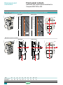
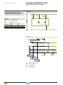
TM-D and TM-G thermal-magnetic trip units
DB112046
TM thermal-magnetic and MA magnetic trip
units
Circuit breakers equipped with thermal-magnetic trip units are used mainly in
industrial and commercial electrical distribution applications:
b TM-D, for protection of cables on distribution systems supplied by transformers
b TM-G, with a low pick-up for generators (lower short-circuit currents than with
transformers) and distribution systems with long cable lengths (fault currents limited
by the impedance of the cable).
Protection ..............................................................................
Thermal protection (Ir)
Thermal overload protection based on a bimetal strip providing an inverse time curve
I2t, corresponding to a temperature rise limit. Above this limit, the deformation of the
strip trips the circuit breaker operating mechanism.
This protection operates according to:
b Ir that can be adjusted in amps from 0.7 to 1 times the rating of the trip unit (16 A to
250 A), corresponding to settings from 11 to 250 A for the range of trip units
b a non-adjustable time delay, defined to ensure protection of the cables.
Magnetic protection (Im)
Short-circuit protection with a fixed or adjustable pick-up Im that initiates
instantaneous tripping if exceeded.
b TM-D: fixed pick-up, Im, for 16 to 160 A ratings and adjustable from 5 to 10 x In for
200 and 250 A ratings
b fixed pick-up for 16 to 630 A ratings.
Protection against insulation faults
Two solutions are possible by adding:
b a Vigi module acting directly on the trip unit of the circuit breaker
b a Vigirex relay connected to an MN or MX voltage release.
Protection versions
b 3-pole:
v 3P 3D: 3-pole frame (3P) with detection on all 3 poles (3D)
v 3P 2D: 3-pole frame (3P) with detection on 2 poles (2D).
b 4-pole:
v 4P 3D: 4-pole frame (4P) with detection on 3 poles (3D).
v 4P 4D: 4-pole frame (4P) with detection on all 4 poles (same threshold for phases
and neutral).
DB112047
MA magnetic trip units
In distribution applications, circuit breakers equipped with MA magnetic-only trip
units are used for:
b short-circuit protection of secondary windings of LV/LV transformers with overload
protection on the primary side.
b as an alternative to a switch-disconnector at the head of a switchboard in order to
provide short-circuit protection.
Their main use is however for motor protection applications, in conjunction with a
thermal relay and a contactor or motor starter (see "Motor protection", page A-36).
Protection ..............................................................................
Magnetic protection (Im)
Short-circuit protection with an adjustable pick-up Im that initiates instantaneous
tripping if exceeded.
b Im = In x ... set in amps on an adjustment dial
covering the range 6 to 14 x In
for 2.5 to 100 A ratings or 9 to 14 In for 150 to 220 A ratings.
Note: all the trip units have a transparent lead-sealable cover
that protects access to the adjustment dials.
A-14
Protection versions
b 3-pole (3P 3D): 3-pole frame (3P) with detection on all 3 poles (3D).
b 4-pole (4P 3D): 4-pole frame (4P) with detection on 3 poles (3D).
version: 1.0
559E1200.indd
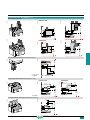
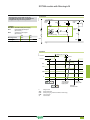
Thermal-magnetic trip units
Ratings (A)
Circuit breaker
In at 40 °C (1)
TM16D to 250D
TM16G to 63G
16 25 32 40 50 63 80 100 125 160 200 250
16 25 40 63
Compact NSX100
b
b
b
b
b
b
b
b
-
-
-
-
b
b
b
b
Compact NSX160
-
-
b
b
b
b
b
b
b
b
-
-
-
b
b
b
Compact NSX250
-
-
-
-
-
b
b
b
b
b
b
b
-
-
b
b
Ir = In x ...
adjustable in amps from 0.7 to 1 x In
Thermal protection
Pick-up (A)
tripping between
1.05 and 1.20 Ir
Time delay (s)
tr
non-adjustable
tr at 1.5 x In
120 to 400
non-adjustable
120 to 400
tr at 6 x Ir
15
-
Pick-up (A)
Im
fixed
accuracy ±20 %
Compact NSX100
190 300 400 500 500 500 640 800
63 80
80
125
Compact NSX160/250
190 300 400 500 500 500 640 800 1250 1250 5 to 10xIn
63 80
80
125
tm
fixed
Magnetic protection
Time delay
adjustable
fixed
Neutral protection
Unprotected neutral
4P 3D
no detection
no 4P3D version
Fully protected neutral
4P 4D
1 x Ir
1 x Ir
Magnetic trip units
MA 2.5 to 220
Ratings (A)
2.5
6.3
12.5
25
50
100
150
220
b
b
b
b
b
b
-
-
Circuit breaker
In at 65 °C
Compact NSX100
Compact NSX160
-
-
-
b
b
b
b
-
Compact NSX250
-
-
-
-
-
b
b
b
Instantaneous magnetic protection
Pick-up (A)
accuracy ±20 %
Im = In x ...
adjustable in amps
from 6 to 14 x In (9 settings)
Time delay (ms)
tm
none
adjustable in amps from 9 to
14 x In
(1) For temperatures greater than 40°C, the thermal protection characteristics are modified. See the temperature derating table.
559E1200.indd
version: 1.0
A-15
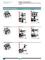
Functions and
characteristics
Protection of distribution systems
Micrologic 2 trip units can be used on
Compact NSX100 to 630 circuit breakers
with performance levels B/F/H/N/S/L.
They provide:
b standard protection of distribution cables
b indication of:
v overloads (via LEDs)
v overload tripping (via the SDx relay
module).
Circuit breakers equipped with Micrologic
1.3-M trip units, without thermal protection,
are used in certain applications to replace
switch-disconnectors at the head of
switchboards. Micrologic 1.3-M trip units are
dedicated to Compact NSX400/630 A circuit
breakers.
Micrologic 2
DB112050
Micrologic 2 and 1.3-M trip units
Circuit breakers equipped with Micrologic 2 trip units can be used to protect
distribution systems supplied by transformers. For generators and long cables,
Micrologic 2-G trip units offer better suited low pick-up solutions (see page A-50).
Protection ..............................................................
Settings are made using the adjustment dials with fine adjustment possibilities.
Overloads: Long time protection (Ir)
Inverse time protection against overloads with an adjustable current pick-up Ir set
using a dial and a non-adjustable time delay tr.
Short-circuits: Short-time protection with fixed time delay (Isd)
Protection with an adjustable pick-up Isd. Tripping takes place after a very short
delay used to allow discrimination with the downstream device.
Short-circuits: Non-adjustable instantaneous protection
Instantaneous short-circuit protection with a fixed pick-up.
PB103377
DB112051
Neutral protection
b On 3-pole circuit breakers, neutral protection is not possible.
b On four-pole circuit breakers, neutral protection may be set using a three-position
switch:
v 4P 3D: neutral unprotected
v 4P 3D + N/2: neutral protection at half the value of the phase pick-up, i.e. 0.5 x Ir
v 4P 4D: neutral fully protected at Ir.
DB112019
Indications.............................................................
Front indications
b Green “Ready” LED: flashes slowly when the circuit breaker is ready to trip in the
event of a fault.
b Orange overload pre-alarm LED: steady on when I > 90 % Ir
b Red overload LED: steady on when I > 105 % Ir
Remote indications
An overload trip signal can be remoted by installing an SDx relay module inside the
circuit breaker.
This module receives the signal from the Micrologic electronic trip unit via an optical
link and makes it available on the terminal block. The signal is cleared when the
circuit breaker is reclosed. For description, see page A-81.
SDx remote indication relay
module with its terminal block.
Note: all the trip units have a transparent lead-sealable cover
that protects access to the adjustment dials.
A-16
DB112106
Micrologic 1.3-M for magnetic protection only
50A
Micrologic 1.3-M trip units provide magnetic protection only, using electronic
technology. They are dedicated to 400/630 A 3-pole (3P 3D) circuit breakers or 4pole circuit breakers with detection on 3 poles (4P, 3D) and are used in certain
applications to replace switch-disconnectors at the head of switchboards. They are
especially used in 3-pole versions for motor protection, see page A-40.
version: 1.0
559E1200.indd
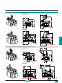
Micrologic 2
Ratings (A)
In at 40 °C (1)
40
100
160
250
400
630
Circuit breaker
Compact NSX100
b
b
-
-
-
-
Compact NSX160
b
b
b
-
-
-
Compact NSX250
b
b
b
b
-
-
Compact NSX400
-
-
-
b
b
-
Compact NSX630
-
-
-
b
b
b
L Long-time protection
Pick-up (A)
tripping between
1.05 and 1.20 Ir
value depending on trip unit rating (In) and setting on dial
In = 40 A
Io =
18
18
20
23
25
28
32
36
40
In = 100 A
Io =
40
45
50
55
63
70
80
90
100
In = 160 A
Io =
63
70
80
90
100
110
125
150
160
In = 250 A (NSX250)
Io =
100
110
125
140
160
175
200
225
250
In = 250 A (NSX400)
Io =
70
100
125
140
160
175
200
225
250
In = 400 A
Io =
160
180
200
230
250
280
320
360
400
In = 630 A
Io =
250
280
320
350
400
450
500
570
630
Ir = Io x ...
Time delay (s)
accuracy 0 to -20%
Ii
Io
9 fine adjustment settings from 0.9 to 1 (0.9 - 0.92 - 0.93 - 0.94 - 0.95 - 0.96 0.97 - 0.98 - 1) for each value of Io
tr
non-adjustable
1.5 x Ir
400
6 x Ir
16
7.2 x Ir
Thermal memory
11
20 minutes before and after tripping
S0 Short-time protection with fixed time delay
Pick-up (A)
accuracy ±10 %
Isd = Ir x ...
1.5
Time delay (ms)
tsd
non-adjustable
I
Non-tripping time
20
Maximum break time
80
2
3
4
5
6
2400
3000
4800
6900
7
8
10
Instantaneous protection
Pick-up (A)
accuracy ±15 %
Ii non-adjustable
600
Non-tripping time
Maximum break time
10 ms
50 ms for I > 1.5 Ii
1500
(1) If the trip units are used in high-temperature environments, the Micrologic setting must take into account the thermal limitations of the circuit breaker. See the
temperature derating table.
Micrologic 1.3-M
Ratings (A)
In at 65 °C
320
500
Circuit breaker
Compact NSX400
b
-
Compact NSX630
b
b
S Short time protection
Pick-up (A)
accuracy ±15 %
Isd
Time delay (ms)
tsd
non-adjustable
Non-tripping time
Maximum break time
20
60
I
adjustable directly in amps
9 settings: 1600, 1920, 2440, 2560,
2880, 3200, 3520, 3840, 4160 A
9 settings: 2500, 3000, 3500, 4000,
4500, 5000, 5500, 6000, 6500 A
Instantaneous protection
Pick-up (A)
accuracy ±15 %
559E1200.indd
Ii non-adjustable
4800
Non-tripping time
Maximum break time
0
30 ms
6500
version: 1.0
A-17
Functions and
characteristics
Protection of distribution systems
Micrologic 5 / 6 A (Ammeter) or E (Energy)
trip units can be used on Compact NSX100
to 630 circuit breakers with performance
levels B/F/H/N/S/L. They all have a display
unit.
They offer basic LSI protection (Micrologic 5)
or LSI and ground-fault protection G
(Micrologic 6).
They also offer measurement, alarm and
communication functions.
DB115566
Measurement
Display
Settings
DB112109
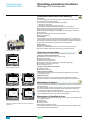
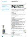
Micrologic 5 / 6 A or E trip units
Protection ……………………………………………
Settings can be adjusted in two ways, using the dials
and/or the keypad
.
The keypad can be used to make fine adjustments in 1 A steps below the maximum
value defined by the setting on the dial. Access to setting modifications via the
keypad is protected by a locking function displayed on the screen and controlled
by a microswitch
. The lock is activated automatically if the keypad is not used for
5 minutes. Access to the microswitch is protected by a transparent lead-sealable
cover. With the cover closed, it is still possible to display the various settings and
measurements using the keypad.
Overloads: Long time protection (Ir)
Inverse time protection against overloads with an adjustable current pick-up Ir set
using a dial or the keypad for fine adjustments. The time delay tr is set using the
keypad.
Maintenance
Short-circuits: Short-time protection (Isd)
Short-circuit protection with an adjustable pick-up Isd and adjustable time delay tsd,
with the possibility of including a portion of an inverse time curve (I2t On).
Short-circuits: Instantaneous protection (Ii)
Instantaneous protection with adjustable pick-up Ii.
Additional ground fault protection (Ig) on Micrologic 6
Residual type ground-fault protection with an adjustable pick-up Ig (with Off position)
and adjustable time delay tg. Possibility of including a portion of an inverse time
curve (I2t On).
Trip unit menus.
Neutral protection
b On 4-pole circuit breakers, this protection can be set via the keypad:
v Off: neutral unprotected
v 0.5: neutral protection at half the value of the phase pick-up, i.e. 0.5 x Ir
v 1.0: neutral fully protected at Ir
v OSN: Oversized neutral protection at 1.6 times the value of the phase pick-up.
Used when there is a high level of 3rd order harmonics (or orders that are multiples
of 3) that accumulate in the neutral and create a high current. In this case, the device
must be limited to Ir = 0.63 x In for the maximum neutral protection setting of 1.6 x Ir.
b With 3-pole circuit breakers, the neutral can be protected by installing an external
neutral sensor with the output (T1, T2) connected to the trip unit.
DB115567
Isd fault
Faulty phase
Interrupted current
PB103377
Display of interrupted current.
Zone selective interlocking (ZSI)
A ZSI terminal block may be used to interconnect a number of Micrologic control
units to provide zone selective interlocking for short-time (Isd) and ground-fault (Ig)
protection, without a time delay. For Compact NSX 100 to 250, the ZSI function is
available only in relation to the upstream circuit breaker (ZSI out).
Display of type of fault ..........................................
On a fault trip, the type of fault (Ir, Isd, Ii, Ig), the phase concerned and the interrupted
current are displayed. An external power supply is required.
Indications.............................................................
Front indications
b Green “Ready” LED: flashes slowly when the circuit breaker is ready to trip in the
event of a fault.
b Orange overload pre-alarm LED: steady on when I > 90 % Ir
b Red overload LED: steady on when I > 105 % Ir
SDx remote indication relay
module with its terminal block.
Note: all the trip units have a transparent lead-sealable cover
that protects access to the adjustment dials.
A-18
Remote indications
An SDx relay module installed inside the circuit breaker can be used to remote the
following information:
b overload trip
b overload prealarm (Micrologic 5) or ground fault trip (Micrologic 6).
This module receives the signal from the Micrologic electronic trip unit via an optical
link and makes it available on the terminal block. The signal is cleared when the
circuit breaker is closed.
These outputs can be reprogrammed to be assigned to other types of tripping or
alarm. The module is described in detail in the section dealing with accessories.
version: 1.0
559E1200.indd
Protection
Micrologic 5 / 6 A or E trip units
Ratings (A)
In at 40 °C (1)
40
100
160
250
400
Circuit breaker
Compact NSX100
b
b
-
-
-
-
Compact NSX160
b
b
b
-
-
-
Compact NSX250
b
b
b
b
-
-
Compact NSX400
-
-
-
-
b
-
Compact NSX630
-
-
-
-
b
b
630
L Long-time protection
Pick-up (A)
tripping between
1.05 and 1.20 Ir
Time delay (s)
accuracy 0 to -20 %
Ir = ...
tr = ...
dial setting
value depending on trip unit rating (In) and setting on dial
In = 40 A
Io =
18
18
20
23
25
28
32
36
40
In = 100 A
Io =
40
45
50
55
63
70
80
90
100
In = 160 A
Io =
63
70
80
90
100
110
125
150
160
In = 250 A
Io =
100
110
125
140
150
175
200
225
250
In = 400 A
Io =
160
180
200
230
250
280
320
360
400
In = 630 A
Io =
250
280
320
350
400
450
500
570
630
keypad setting
Fine adjustment in 1 A steps below maximum value set on dial
keypad setting
0.5
1
2
4
8
16
1.5 x Ir
15
25
50
100
200
400
6 x Ir
0.5
1
2
4
8
16
7.2 x Ir
0.35
0.7
1.4
2.8
5.5
11
Thermal memory
20 minutes before and after tripping
S Short-time protection with adjustable time delay
Pick-up (A)
accuracy ±10 %
Isd = Ir x ... dial setting
Time delay (s)
tsd = ...
I
1.5
2
3
4
5
6
7
8
10
Fine adjustment in 0.5 x Ir steps using the keypad
I2Off
0
0.1
0.2
0.3
0.4
I2On
-
0.1
0.2
0.3
0.4
Non-tripping time (ms)
20
80
140
230
350
Maximum break time (ms)
80
140
200
320
500
keypad
setting
Instantaneous protection
Pick-up (A)
accuracy ±15 %
Ii = In x
keypad setting
Non-tripping time
Maximum break time
Adjustment in steps of 0.5 x In over the range 1.5 x In to:
15 x In (NSX100/160), 12 x In (NSX250/400) or 11 x In (NSX630)
10 ms
50 ms for I > Ii
G Ground-fault protection - for Micrologic 6 A or E
Pick-up (A)
accuracy ±10 %
Ig = In x
dial setting
In = 40 A
0.4
0.4
0.5
0.6
0.7
0.8
0.9
1
Off
In > 40 A
0.2
0.3
0.4
0.5
0.6
0.7
0.8
1
Off
Fine adjustment in 0.05 A steps using the keypad
Time delay (s)
Test
I2Off
0
0.1
0.2
0.3
0.4
I2On
-
0.1
0.2
0.3
0.4
Non-tripping time (ms)
20
80
140
230
350
Maximum break time (ms)
80
140
200
320
500
Ig function
built-in
tg = ...
keypad
setting
(1) If the trip units are used in high-temperature environments, the Micrologic setting must take into account the thermal limitations of the circuit breaker. See the
temperature derating table.
559E1200.indd
version: 1.0
A-19
Functions and
characteristics
Power Meter functions
In addition to protection functions,
Micrologic 5 / 6 trip units offer all the
functions of Power Meter products as well
as operating-assistance for the circuit
breaker.
b display of settings
b measurement functions:
v Ammeter (A)
v Energy (E)
b alarms
b time-stamped histories and event tables
b maintenance indicator
b communication.
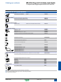
Micrologic A and E measurement functions are made possible by Micrologic
intelligence and the accuracy of the sensors. They are handled by a microprocessor
that operates independent of protection functions.
PB103365
Electronic Micrologic 5 / 6 A or E
Display ..................................................................
Micrologic LCD
The user can display all the protection settings and the main measurements on the
LCD screen of the trip unit.
b Micrologic A: instantaneous rms current measurements
b Micrologic E: voltage, frequency and power measurements and energy metering,
in addition to the measurements offered by Micrologic A
To make the display available under all conditions and increase operating comfort,
an external power supply is recommended for Micrologic A.
It is indispensable to:
b display faults and interrupted current measurements
b use all the functions of Micrologic E (e.g. metering of low power and energy
values)
b ensure operation of the communication system.
The external power supply can be shared by several devices. For description, see
page A-32.
FDM121 display unit
An FDM121 switchboard display unit can be connected to a Micrologic trip unit using
a prefabricated cord to display all measurements on a screen. The result is a
veritable 96 x 96 mm Power Meter.
In addition to the information displayed on the Micrologic LCD, the FDM121 screen
shows demand, power quality and maximeter/minimeter values along with alarms,
histories and maintenance indicators.
The FMD121 display unit requires a 24 V DC power supply. The Micrologic trip unit is
supplied by the same power supply via the cord connecting it to the FDM121.
Micrologic built-in LCD display showing an energy
measurement.
DB112211
PC screen
When the Micrologic, with or without an FDM121 switchboard display unit, is
connected to a communication network, all information can be accessed via a PC.
Main Menu
Quick View
Metering
Measurements .....................................................
Alarms
Services
ESC
Instantaneous rms measurements
OK
The Micrologic A and E continuously display the RMS value of the highest current of
the three phases and neutral (Imax). The navigation buttons
can be used to
scroll through the main measurements.
In the event of a fault trip, the current interrupted is memorised.
The Micrologic A measures phase, neutral, ground fault currents.
The Micrologic E offers voltage, frequency and power measurements in addition to
the measurements provided by Micrologic A
FDM121 display: navigation.
I
I1
310
A
I2
315
A
DB112132
DB112131
Maximeters / minimeters
V
4/7
402 V
%
100
120
398 V
%
100
120
401 V
%
100
120
U1
%
I3 302
A
%
IN 23
U2
A
U3
%
ESC
Every instantaneous measurement provided by Micrologic A or E can be associated
with a maximeter/minimeter. The maximeters for the highest current of the 3 phases
and neutral, the demand current and power can be reset via the trip unit keypad, the
FDM121 display unit or the communication system.
Energy metering
%
ESC
The Micrologic E also measures the energy consumed since the last reset of the
meter. The active energy meter can be reset via the keypad and the FDM121 display
unit or the communication system.
Voltage.
DB112134
DB112133
Current.
PQS
Demand and maximum demand values
E
P
64
kW
Ep
14397
kWh
Q
38
kVar
Eq
8325
kVarh
S
51
kVA
Es
13035
kVAh
ESC
Power.
ESC
Consumption.
Examples of measurement screens on the FDM121 display
unit.
A-20
Micrologic E also calculates demand current and power values. These calculations
can be made using a block or sliding interval that can be set from 5 to 60 minutes in
steps of 1 minute. The window can be synchronised with a signal sent via the
communication system. Whatever the calculation method, the calculated values can
be recovered on a PC via Modbus communication.
Ordinary spreadsheet software can be used to provide trend curves and forecasts
based on this data. They will provide a basis for load shedding and reconnection
operations used to adjust consumption to the subscribed power.
Power quality
Micrologic E calculates power quality indicators taking into account the presence of
harmonics up to the 15th order, including the total harmonic distortion (THD) of
current and voltage.
version: 1.0
559E1200.indd
PB103364
PB103360
PB103354
Micrologic 5 / 6 integrated Power Meter functions
Type
Display
A
E
Micrologic
LCD
FDM121
display
Ir, tr, Isd, tsd, Ii, Ig, tg
b
b
b
Phases and neutral
I1, I2, I3, IN
b
b
b
b
Average of phases
Iavg = (I1 + I2 + I3) / 3
b
b
-
b
Highest current of the 3 phases and neutral Imax of I1, I2, I3, IN
b
b
b
b
Ground fault (Micrologic 6)
% Ig (pick-up setting)
b
b
b
b
Current unbalance between phases
% Iavg
-
b
-
b
Phase-to-phase
U12, U23, U31
-
b
b
b
Phase-to-neutral
V1N, V2N, V3N
-
b
b
b
Average of phase-to-phase voltages
Uavg = (U12 + U21 + U23) / 3
-
b
-
b
Average of phase-to-neutral voltages
Vavg = (V1N + V2N + V3N) / 3
-
b
-
b
Ph-Ph and Ph-N voltage unbalance
% Uavg and % Vavg
-
b
-
b
Phase sequence
1-2-3, 1-3-2
-
b
b
b
Frequency (Hz)
Power system
f
-
b
b
b
Power
Active (kW)
P, total and per phase
-
b
b
b
Reactive (kVAR)
Q, total and per phase
-
b
-
b
Apparent (kVA)
S, total and per phase
-
b
-
b
Power factor and cos (fundamental)
PF and cos K, total and per phase
-
b
-
b
Associated with instantaneous rms
measurements
Reset via Micrologic or FDM121 display unit
b
b
-
b
Active (kW), reactive (kVARh), apparent
(kVAh)
Total since last reset
-
b
b
b
Present value on the selected window
-
b
-
b
Maximum demand since last reset
-
b
-
b
Active (kWh), reactive (kVAR),
apparent (kVA)
Present value on the selected window
-
b
-
b
Maximum demand since last reset
-
b
-
b
Sliding, fixed or com-synchronised
Adjustable from 5 to 60 minutes in 1 minute
steps
-
b
-
(2)
Of voltage with respect to rms value
THDU,THDV of the Ph-Ph and Ph-N voltage
-
b
-
b
Of current with respect to rms value
THDI of the phase current
-
b
-
b
Display of protection settings
Pick-ups (A) and delays
All settings can be displayed
Measurements
Instantaneous rms measurements
Currents (A)
Voltages (V)
Maximeters / minimeters
Energy metering
Energy
Absolute or signed mode (1)
Demand and maximum demand values
Demand current (A)
Demand power
Calculation window
Phases and neutral
Power quality
Total harmonic
distortion (%)
(1) Absolute mode: E absolute = E out + E in; Signed mode: E signed = E out - E in.
(2) Available via the communication system only.
Additional technical characteristics
Measurement accuracy
Accuracies are those of the entire measurement system, including the sensors:
b Current: Class 1 as per IEC 61557-12
b Voltage: 0.5 %
b Power and energy: Class 2 as per IEC 61557-12
b Frequency: 0.1 %.
559E1200.indd
version: 1.0
A-21
Functions and
characteristics
Operating-assistance functions
Micrologic 5 / 6 A or E trip units
Personalised alarms with time-stamping ............
PB103365
Alarm types
The user can assign an alarm to all Micrologic A or E measurements or events:
b up to 12 alarms can be used together:
v two alarms are predefined and activated automatically:
- Micrologic 5: overload (Ir)
- Micrologic 6: overload (Ir) and ground fault (Ig)
v thresholds, priorities and time delays can be set for ten other alarms.
b the same measurement can be used for different alarms to precisely monitor
certain values, e.g. the frequency or the voltage
b alarms can also be assigned to various states: phase lead/lag, four quadrants,
phase sequence
b selection of display priorities, with pop-up possibility
b alarm time-stamping.
Alarm settings
Alarms cannot be set via the keypad or the FDM121 display unit. They are set via
communication with the PC. Set-up includes the threshold, priority, activation delay
before display and deactivation delay. It is also possible to reprogram the standard
assignment for the two SDx relay outputs to user-selected alarms.
Alarm reading
Remote alarm indications
b reading on FDM121 display unit or on PC via the communication system
b remote indications via SDx relay with two output contacts for alarms.
Micrologic built-in LCD display.
Histories and event tables.....................................
DB112212
Micrologic A and E have histories and event tables that are always active.
Three types of time-stamped histories
b Tripping due to overruns of Ir, Isd, Ii, Ig: last 17 trips
b Alarms: last 10 alarms
b Operating events: last 10 events
Each history record is stored with:
b indications in clear text in a number of user-selectable languages
b time-stamping: date and time of event
b status: pick-up / drop-out
Main Menu
Quick View
Metering
Alarms
Services
ESC
OK
Two types of time-stamped event tables
b Protection settings
b Minimeters / maximeters
Alarm History
2/3
Total reactive
Power
DB112128
DB112127
FDM121 display: navigation.
2/3
Date:
07 May 2007
Date:
10 Nov 2007
Time:
10:28:03.01 PM
Time:
06:35:08.04 AM
ESC
OK
ESC
Alarm History
2/3
Under voltage
Pick-up
Alarm History
05 Nov 2007
Date:
Time:
02:31:03.61 AM
Time:
OK
ESC
3/3
05 Nov 2007
02:32:26.12 AM
OK
Alarm pick-up and drop-out.
Examples of operating-assistance screens on the FDM121
display unit.
A-22
Embedded memory
Micrologic A and E have a non-volatile memory that saves all data on alarms,
histories, event tables, counters and maintenance indicators even if power is lost.
Maintenance indicators .........................................
Under voltage
Drop-out
Date:
ESC
OK
Phase unbalance alarm.
DB112130
Overpower alarm.
DB112129
Alarm History
Over maximum
Current unbalance
Display of alarms and tables
The time-stamped histories and event tables may be displayed on a PC via the
communication system.
Micrologic A and E have indicators for, among others, the number of operating
cycles, contact wear and operating times (operating hours counter) of the Compact
NSX circuit breaker.
It is possible to assign an alarm to the operating cycle counter to plan maintenance.
The various indicators can be used together with the trip histories to analyse the
level of stresses the device has been subjected to.
The information provided by the indicators cannot be displayed on the Micrologic
LCD. It is displayed on the PC via the communication system.
Management of installed devices
Each circuit breaker equipped with a Micrologic 5 or 6 trip unit can be identified via the
communication system:
b serial number
b firmware version
b hardware version
b device name assigned by the user.
This information together with the previously described indications provides a clear
view of the state of the installed devices.
version: 1.0
559E1200.indd
PB103364
PB103360
PB103354
Micrologic 5 / 6 operating assistance functions
Type
Display
A
E
Micrologic
LCD
FDM121
display
b
b
-
(2)
Operating assistance
Personalised alarms
Settings
Up to 10 alarms assigned to all A and E measurements
Phase lead/lag, four quadrants, phase sequence, display priority selection
Display
Alarms and tripping
Remote indications
Activation of two dedicated contacts on SDx module
Time-stamped histories
Trips
Cause of tripping
Ir, Isd, Ii (Micrologic 5, 6)
(last 17)
(timestamping with ms)
Ig (Micrologic 6)
Alarms
(last 10)
Operating events
(last 10)
Time stamping
Event types
Presentation
-
b
-
(2)
b
b
b
b
-
(2)
-
b
b
-
(2)
b
b
b
b
-
(2)
Modification of protection setting by dial
Opening of keypad lock
Test via keypad
Test via external tool
Time setting (date and time)
Reset for maximeter/minimeter and energy meter
b
b
b
b
b
b
b
b
(2)
Date and time, text, status
b
b
-
(2)
(2)
(2)
(2)
(2)
(2)
b
Time-stamped event tables
Protection settings
Min/Max
Setting modified (value displayed)
Ir
b
b
-
(2)
Time stamping
Date and time of modification
b
b
-
(2)
Previous value
Value before modification
b
b
-
(2)
Values monitored
I1
I2
I3
IN
b
-
-
(2)
I1
I2
I3
IN
-
b
-
(2)
tr
Isd
tsd
Ii
Ig
tg
U12 U23 U31 f
Time-stamping of each value
Date and time of min/max record
b
b
-
(2)
Current min/max value
Min/max value
b
b
-
(2)
Mechanical cycles (1)
Assignable to an alarm
b
b
-
(2)
Electrical cycles (1)
Assignable to an alarm
b
b
-
(2)
Trips
One per type of trip
b
b
-
(2)
Alarms
One for each type of alarm
b
b
-
(2)
Hours
Total operating time (hours)
b
b
-
(2)
Indicator
Contact wear
%
b
b
-
(2)
Load profile
Hours at different load levels
% of hours in four current ranges: 0-49 % In, 50-79 %
In, 80 - 89 % In and u 90 % In
b
b
-
(2)
Maintenance indicators
Counter
(1) The BSCM module (page A-27) is required for these functions.
(2) Available via the communication system only.
Additional technical characteristics
Contact wear
Each time Compact NSX opens, the Micrologic 5 / 6 trip unit measures the interrupted current
and increments the contact-wear indicator as a function of the interrupted current, according to
test results stored in memory. Breaking under normal load conditions results in a very slight
increment. The indicator value may be read on the FDM121 display. It provides an estimation of
contact wear calculated on the basis of the cumulative forces affecting the circuit breaker. When
the indicator reaches 80%, it is advised to replace the circuit breaker to ensure the availability of
the protected equipment.
Circuit breaker load profile
Micrologic 5 / 6 calculates the load profile of the circuit breaker protecting a load circuit. The
profile indicates the percentage of the total operating time at four current levels (% of breaker In):
b 0 to 49 % In
b 50 to 79 % In
b 80 to 89 % In
b u 90 % In.
This information can be used to optimise use of the protected equipment or to plan ahead for
extensions.
559E1200.indd
version: 1.0
A-23
Functions and
characteristics
Switchboard-display functions
Micrologic measurement capabilities come
into full play with the FDM121 switchboard
display. It connects to Compact NSX via a
simple cord and displays Micrologic
information. The result is a true integrated
unit combining a circuit breaker and a
Power Meter. Additional operating
assistance functions can also be displayed.
FDM121 switchboard display
Micrologic 5 / 6 A or E trip units
The FDM121 is a switchboard display unit that can be integrated in the Compact
NSX100 to 630 A system. It uses the sensors and processing capacity of the
Micrologic trip unit. It is easy to use and requires no special software or settings. It is
immediately operational when connected to the Compact NSX by a simple cord.
The FDM121 is a large display, but requires very little depth. The anti-glare graphic
screen is backlit for very easy reading even under poor ambient lighting and at sharp
angles.
Display of Micrologic measurements and alarms
The FDM121 is intended to display Micrologic 5 / 6 measurements, alarms and
operating information. It cannot be used to modify the protection settings.
Measurements may be easily accessed via a menu.
All user-defined alarms are automatically displayed. The display mode depends on
the priority level selected during alarm set-up:
b high priority: a pop-up window displays the time-stamped description of the alarm
and the orange LED flashes
b medium priority: the orange "Alarm" LED goes steady on
b low priority: no display on the screen.
All faults resulting in a trip automatically produce a high-priority alarm, without any
special settings required.
In all cases, the alarm history is updated.
If power to the FDM121 fails, all information is stored in the Micrologic non-volatile
memory. The data is automatically recovered when power is restored and can be
consulted via the communication system.
Status indications and remote control
When the circuit breaker is equipped with the BSCM module (page A-27), the
FDM121 display can also be used to view circuit breaker status conditions:
b O/F: ON/OFF
b SD: trip indication
b SDE: Fault-trip indication (overload, short-circuit, ground fault)
PB103807-32
PB103582
Main characteristics
FDM121 display.
Surface mount accessory.
b 96 x 96 x 30 mm screen requiring 10 mm behind the door (or 20 mm when the
24 volt power supply connector is used).
b White backlighting.
b Wide viewing angle: vertical ±60°, horizontal ±30°.
b High resolution: excellent reading of graphic symbols.
b Alarm LED: flashing orange for alarm pick-up, steady orange after operator reset if
alarm condition persists.
b Operating temperature range -10 °C to +55 °C.
b CE / UL marking.
b 24 V DC power supply, with tolerances 24 V -20 % (19.2 V) to 24 V +10 % (26.4 V).
When the FDM121 is connected to the communication network, the 24 V is supplied
by the communication system wiring system.
b Consumption 40 mA.
PB103581-31
Mounting
The FDM121 is easily installed in a switchboard.
b Standard door cut-out 92 x 92 mm.
b Attached using clips.
To avoid a cut-out in the door, an accessory is available for surface mounting by
drilling only two 22 mm diameter holes.
The FDM121 degree of protection is IP54 in front. IP54 is maintained after
switchboard mounting by using the supplied gasket during installation.
Connection
Connection with FDM121 display unit.
A-24
The FDM121 is equipped with:
b a 24 V DC terminal block:
v plug-in type with 2 wire inputs per point for easy daisy-chaining
v power supply range of 24 V -20 % (19.2 V) to 24 V +10 % (26.4 V)
b two RJ45 jacks.
The Micrologic connects to the internal communication terminal block on the
Compact NSX via the pre-wired NSX cord. Connection to one of the RJ45
connectors on the FDM121 automatically establishes communication between the
Micrologic and the FDM121 and supplies power to the Micrologic measurement
functions.
When the second connector is not used, it must be fitted with a line terminator.
version: 1.0
559E1200.indd
DB112135
Navigation
I
I1
310
A
I2
%
I3 302
A
%
IN 23
%
ESC
315
Five buttons are used for intuitive and fast navigation.
The “Context” button may be used to select the type of display (digital, bargraph,
analogue).
The user can select the display language (Chinese, English, French, German,
Italian, Portuguese, Spanish, etc.) Other languages can be downloaded.
A
A
%
Screens
1
1
2
3
4
5
6
2 3 4
Main menu
When powered up, the FDM121 screen automatically displays the ON/OFF status of
the device.
5 6
Escape
Down
OK
Up
Context
Alarm LED
Quick view
Metering
Alarms
Services.
DB112137
DB112136
When not in use, the screen is not backlit. Backlighting can be activated by pressing
one of the buttons. It goes off after 3 minutes.
Produit Id
Micrologic 5.3A
Serial number:
Part number:
Alarms
Services
1.02
ESC
I
OK
Quick view.
DB112139
Product identification.
Metering
Access to detailed information
b "Metering" can be used to display the measurement data (I, U-V, f, P, Q, S, E,
THD, PF) with the corresponding min/max values.
b Alarms displays active alarms and the alarm history.
b Services provides access to the operation counters, energy and maximeter reset
function, maintenance indicators, identification of modules connected to the internal
bus and FDM121 internal settings (language, contrast, etc.)
Metering
P07451
ESC
DB112138
Main Menu
Quick View
LU432091
Firmware:
Fast access to essential information
b “Quick view” provides access to five screens that display a summary of essential
operating information (I, U, f, P, E, THD, circuit breaker On / Off).
U Average
9/10
387 V
%
100
120
392 V
%
100
120
388 V
%
100
120
avg
U-V
PQS
MIN
E
MAX
F - PF - cos Φ
ESC
OK
ESC
NonResettableEnergy
1/3
EpIN
5111947
kWh
EpOut
12345678
kWh
Metering: U average.
DB112141
DB112140
Metering: sub-menu.
Display
Contrast
Brightness
Language
ESC
Metering: meter.
559E1200.indd
ESC
OK
Services.
version: 1.0
A-25
Functions and
characteristics
Compact NSX communication
All Compact NSX devices can be equipped
with the communication function via a
prewired connection system and a Modbus
network interface.
The interface can be connected directly or
via the FDM121 switchboard display unit.
Four functional levels can be combined to
adapt to all supervision requirements.
Four functional levels
Communications modules
The Compact NSX can be integrated in a Modbus communication environment. Four
functional levels can be used separately or combined.
Communication of status indications
This level is compatible with all Compact NSX circuit breakers, whatever the trip unit,
and with all switch-disconnectors. Using the BSCM module, the following information
is accessible:
b ON/OFF position (O/F)
b trip indication (SD)
b fault-trip indication (SDE).
Communication of commands
Also available on all circuit breakers and switch-disconnectors, this level
(communicating remote control) can be used to:
b open
b close
b reset.
Communication of measurements with Micrologic 5 / 6 A or E
This level provides access to all available information:
b instantaneous and demand values
b maximeters/minimeters
b energy metering
b demand current and power
b power quality.
Communication of operating assistance with Micrologic 5 / 6 A or E
b protection and alarm settings
b time-stamped histories and event tables
b maintenance indicators.
Communication components and connections
DB115568
Modbus
DB112060
24 V DC
10
10
1.3 m
Connections
b Compact NSX is connected to the Modbus interface or
FDM121 display unit via the internal terminal block for the NSX
cord equipped with an RJ45 connector.
v cord available in three lengths: 0.35 m, 1.3 m and 3 m.
v insulated 0.35 m version for installations > 480 V AC
v lengths up to 10 m possible using extensions.
b The FDM121 display unit is connected to the Modbus
interface by a communication cable with RJ45 connectors on
both ends.
A-26
1
2
3
4
5
6
7
8
9
10
Modbus network
Modbus interface
NSX cord
Internal terminal block for communication via NSX cord
BSCM module
Prefabricated wiring
Micrologic trip unit
FDM121 display
RJ45 cable
Line terminator (on unused connector if applicable)
version: 1.0
559E1300.indd
Functions
This module, required for connection to the network,
contains the Modbus address (1 to 99) declared by the
user via the two dials in front. It automatically adapts
(baud rate, parity) to the Modbus network in which it is
installed.
It is equipped with a lock-out switch to enable or disable
operations involving writing to Micrologic, i.e. reset,
counter reset, setting modifications, device opening
and closing commands, etc.
There is a built-in test function to check the connections
of the Modbus interface module with the Micrologic and
FDM121 display unit.
Mounting
The module is mounted on a DIN rail. A number of
modules may be clipped one next to the other.
For this, a stacking accessory is available for fast clipconnection of both the Modbus link and the 24 V DC
supply.
The Modbus interface module supplies 24 V DC to the
corresponding Micrologic, FDM121 display and BSCM
module. Module consumption is 60 mA / 24 V DC.
DB112083
Modbus interface module
Modbus interface module.
BSCM module
Functions
The optional BSCM Breaker Status & Control Module
is used to acquire device status indications and control
the communicating remote-control function.
It includes a memory used to manage the maintenance
indicators.
DB112035
Status indications
Indication of device status:
O/F, SD and SDE.
Maintenance indicators
The BSCM module manages the following indicators:
b mechanical operation counter
b electrical operation counter
b history of status indications.
It is possible to assign an alarm to the operation
counters.
Controls
The module can be used to carry out communicating
remote control operations: (open, close and reset) in
different modes (manual, auto).
Five-point Modbus and 24 V DC connector
Two Modbus address dials (1 to 99)
Modbus traffic LED
Lock-out to disable writing to the NSX
Test LED
Test button
Two connectors for RJ45 cable
DB112085
DB112084
1
2
3
4
5
6
7
Mounting
The BSCM module can be installed on all Compact
NSX circuit breakers and switch-disconnectors. It
simply clips into the auxiliary contact slots. It occupies
the slots of one O/F contact and one SDE contact. The
BSCM is supplied with 24 V DC power automatically
via the NSX cord when the communication system is
installed.
BSCM module.
Mounting with stacking accessory.
559E1300.indd
version: 1.0
A-27
Compact NSX communication
Compact NSX uses the Modbus
communication protocol, compatible with
SMS PowerLogic supervision systems.
Two downloadable utilities facilitate
implementation of communication functions.
Modbus
DB115569
Functions and
characteristics
Networks and software
Modbus is the most widely used communication
protocol in industrial networks. It operates in masterslave mode. The devices (slaves) communicate one
after the other with a gateway (master).
Masterpact, Compact NSX, PowerLogic and Sepam
products all operate with this protocol. A Modbus
network is generally implemented on an LV or MV
switchboard scale.
Depending on the data monitored and the desired
refresh rate, a Modbus network connected to a
gateway can serve 4 to 16 devices. For larger
installations, a number of Modbus networks can be
connected to an Ethernet network (TCP/IP/Modbus
protocol) via their gateways.
Automatic
notification
Firewall
Nomad
mode
Internet
Site Intranet
Ethernet (TCP/IP/Modbus)
Consultation
RSU
RCU
EGX400
MPS100
Consultation
RSU
RCU
Modbus
Modbus
FDM121
Masterpact
A-28
Sepam
Compact NSX
version: 1.0
PowerLogic
Power Meter
559E1300.indd
Micrologic utilities
DB112125
b Two utilities, RSU and RCU, presented on the next
page, are available to assist in starting up a
communicating installation. Intended for Compact NSX
and Masterpact, the software can be downloaded from
the Schneider Electric internet site.
b The "Live update" function enables immediate
updating to obtain the most recent upgrades. These
easy-to-use utilities include starting assistance and online help. They are compatible with Microsoft Windows
2000, XP and Vista.
DB112214
RSU configuration screen for a Micrologic 5.2.
Gateway
The gateway has two functions:
b access to the company intranet (Ethernet) by
converting Modbus frames to the TCP/IP/Modbus
protocol
b optional web-page server for the information from
the devices.
Examples include MPS100, EGX400 and EGX100.
RCU mini-supervision screen for current measurements.
DB112126
MPS100
b Plug and play device. It comes loaded with a webpage application for graphic display of currents and
voltages and viewing of circuit-breaker status and
power and energy values.
To use the application, simply declare the Modbus
addresses of the connected slaves. Automatically
recognised devices include all Masterpact and
Compact NSX Micrologic trip units and the
PM500/700/800 and PM9c power monitoring units.
b Can be used for automatic alarm notification via a
messaging server available on the site intranet or via
mobile phones (e-mail converted into SMS).
b Can be used for logging of data that can be
automatically sent as e-mail attachments, e.g. a weekly
consumption report.
Web page.
559E1300.indd
version: 1.0
A-29
Functions and
characteristics
Compact NSX communication
Two utilities, RSU and RCU, are available to
assist in starting up a communicating
installation.
They can be downloaded from the
Schneider Electric internet site and include
a "Live update" function that enables
immediate updating.
RSU (Remote Setting Utility)
RSU and RCU utilities
This utility is used to set the protection functions and alarms for each Masterpact and
Compact NSX device.
After connection to the network and entry of the circuit-breaker Modbus address, the
software automatically detects the type of trip unit installed.
There are two possible operating modes.
Off-line with the software disconnected from the
communication network
For each selected circuit breaker, the user can do the following.
DB112216
Determine the protection settings
The settings are carried out on a screen that shows the front of the trip unit. The
Micrologic setting dials, keypad and screen are simulated for easy use of all
Micrologic setting functions.
Save and duplicate the protection settings
Each configuration created can be saved for subsequent device programming. It can
also be duplicated and used as the basis for programming another circuit breaker.
On-line with the software connected to the network
Similarly, for each selected circuit breaker, the user can do the following.
Display the current settings
The software displays the trip unit and provides access to all settings.
DB112217
View the corresponding protection curves
A graphic curve module in the software displays the protection curve corresponding
to the settings. It is possible to lay a second curve over the first for discrimination
studies.
RSU: Micrologic Remote Setting Utility.
Modify settings in a secure manner
b There are different levels of security:
v password: by default, it is the same for all devices, but can be differentiated for
each device
v locking of the Modbus interface module which must be unlocked before the
corresponding device can be set remotely
v maximum settings limited by the positions of the two dials on the trip unit.
These dials, set by the user, determine the maximum settings that can be made via
the communication system.
b Settings are modified by:
v either direct, on-line setting of the protection settings on the screen
v or by loading the settings prepared in off-line mode. This is possible only if the
positions of the dials allow the new settings.
All manual settings made subsequently on the device have priority.
Program alarms
b Up to 12 alarms can be linked to measurements or events.
b two alarms are predefined and activated automatically:
v Micrologic 5: overload (Ir)
v Micrologic 6: overload (Ir) and ground fault (Ig)
b thresholds, priorities and time delays can be set for 10 other alarms. They may be
selected from a list of 91 alarms
DB112215
Set the outputs of the SDx relays
This is required when the user wants to change the standard configuration and
assign different signals to the 2 outputs of the SDx relay.
RCU (Remote Control Utility)
The RCU utility can be used to test communication for all the devices connected to
the Modbus network. It is designed for use with Compact NSX, Masterpact,
Advantys OTB and Power Meter devices. It offers a number of functions.
Mini supervisor
b Display of I, U, f, P, E and THD measurements for each device, via navigation
b Display of ON/OFF status
Open and close commands for each device
A common or individual password must first be entered.
RCU: Remote Control Utility for communication tests.
A-30
When all functions have been tested, this utility is replaced by the supervision
software selected for the installation.
version: 1.0
559E1300.indd
Supervision software
Schneider Electric electrical installation
supervision, management and expert
system software integrates Compact NSX
identification modules.
Types of software
Masterpact and Compact NSX communication functions are designed to interface
with software dedicated to electrical installations:
b switchboard supervision
b electrical installation supervision
b power system management: electrical engineering expert systems
b process control
b SCADA (Supervisory Control & Data Acquisition), EMS (Enterprise Management
System) or BMS (Building Management System) type software.
DB111370
Integration of Compact NSX
Compact NSX devices are integrated via Modbus interface modules connected via
FDM121 display units or NSX cords.
For easy connection of the different modules, the prefabricated cables are identified
by ULP (Universal Logic Plug) symbols. The connection points on compatible
modules are marked in the same manner.
Schneider Electric solutions
Electrical switchboard supervision via MPS100 or EGX400
Web servers
PE86106-62
Connection symbol for Compact NSX compatible modules.
A simple solution for customers who want to consult the main electrical parameters
of switchboard devices without dedicated software.
Up to 16 switchboard devices are connected via Modbus interfaces to an MPS100 or
EGX400 Ethernet gateway integrating the functions of a web page server. The
embedded Web pages can be easily configured with just a few mouse clicks. The
information they provide is updated in real time.
The Web pages can be consulted using a standard Web browser on a PC connected
via Ethernet to the company Intranet or remotely via a modem. Automatic notification
of alarms and threshold overruns is possible via e-mail or SMS (Short Message
Service).
Electrical installation supervision via PowerView software
PowerLogic® PowerView software is ideally suited to the supervision needs of small
system applications, monitoring up to 32 devices. Installed on a PC under Windows,
it represents a cost-effective and easy-to-implement power-monitoring solution that
offers:
b automatic detection of compatible devices
b real-time monitoring of data including power consumption
b a report generator with a number of pre-defined reports that can be exported to
Excel
b cost allocation
b time-stamped data-logging possibilities
b Modbus serial and Modbus TCP/IP compatible communication.
SMS electrical engineering expert system software
DB112145
PowerView software.
PowerLogic® SMS is a family of web-enabled software products for high-end powermonitoring applications. It is designed for large power systems.
SMS products offer detailed analysis of electrical events, long-duration data logging
and extensive, economical report-building capabilities (e.g. consumption monitoring
and tariff management).
A wide variety of screens can be displayed in real time, including more than 50
tables, analogue meters, bargraphs, alarms logs with links to display waveforms and
predefined reports on energy quality and service costs.
Other software
Compact NSX devices can forward their measurement and operating information to
special software integrating the electrical installation and other technical facilities:
b SCADA process control software: Vijeo CITECT
b BMS Building Management System software: Vista.
Please consult us.
SMS software screen.
559E1300.indd
version: 1.0
A-31
Functions and
characteristics
Accessories for
Micrologic trip units
PB103843-18
External neutral current transformer (ENCT)
The external transformer is a sensor required for a three-pole circuit breaker in a
system with a distributed neutral to measure the neutral current in order to:
b protect the neutral conductor
b protect against insulation faults.
This current transformer can be connected to Micrologic 5 / 6 trip units. The
transformer rating must be compatible with that of the circuit breaker.
Required current transformers for different circuit breaker models
Type of circuit breaker
External neutral current transformers.
NSX100/160/250
25 – 100 A
150 – 250 A
400 – 630 A
NSX400/630
PB103842-47
Rating
Catalogue
number
LV429521
LV430563
LV432575
External neutral voltage tap (ENVT)
The neutral voltage transformer is required for Micrologic E power metering with a
three-pole circuit breaker in a system with a distributed neutral. It is used to connect
the neutral to the Micrologic trip unit to measure phase-to-neutral (Ph-N) voltages.
External neutral voltage tap (cat. no. LV434208).
External 24 V DC power-supply module
PB103583-18
Use
An external 24 V DC power supply is required for installations with communication,
whatever the type of trip unit.
On installations without communication, it is available as an option for Micrologic 5/6
in order to make it possible to:
b modify settings when the circuit breaker is open
b display measurements when the current flowing through the circuit breaker is low
(15 to 50 A depending on the rating)
b maintain the display of the cause of tripping and interrupted current.
External 24 V DC power-supply module.
Characteristics
A single external 24 V DC supply may be used for the entire switchboard.
The required characteristics are:
b output voltage: 24 V DC ±5 %
b ripple: ±1%.
b overvoltage category: OVC IV - as per IEC 60947-1
External 24 V DC power-supply modules with an output current of 1 A are available:
Available external power-supply modules
Power supply
V DC (±5 %)
V AC (+10 %, -15 %)
Output voltage
Ripple
Overvoltage category (OVC)
Cat. no.
24/30
54440
48/60
54441
100/125
54442
110/130
54443
200/240
54444
380/415
54445
24 V DC (±5 %)
±1 %
OVC IV - as per IEC 60947-1
An external 24 V DC power-supply module with an output current of 3 A is also
available:
Available external power-supply modules
Power supply
V DC
V AC
Output voltage
Ripple
Overvoltage category (OVC)
Cat. no.
110/230
110/240
24 V DC (±5 %)
±1 %
OVC II
ABL8RPS24030
Total consumption
To determine the required output current of the 24 V DC power supply, it is necessary
to sum up the currents consumed by the different loads supplied:
Consumption of Compact NSX modules
Module
Micrologic 5/6
BSCM module
FDM121
Modbus communication interface
NSX cord U > 480 V AC
A-32
version: 1.0
Consumption (mA)
20
10
40
60
30
559E1400.indd
PB103790-20
Test battery
This pocket battery connects to the Micrologic test connector. It powers up the
Micrologic and the Ready LED. It supplies the screen and allows settings to be made
via the keypad.
Test battery (cat. no. LV434206).
PB103833-18
Battery module
The battery module is a back-up supply for the external power-supply module. The
input/output voltages are 24 V DC and it can supply power for approximately three
hours (100 mA).
24 V DC power-supply terminal block
The 24 V DC power-supply terminal block can be installed only on Micrologic 5/6 trip
units. It is required to power the trip unit when the trip unit is not connected to an
FDM121 display unit or to the communication system. When used, it excludes
connection of an NSX cord.
PB103789-24
PB103799-24
Battery module (cat. no. 54446).
NSX cord
24 V DC power-supply
terminal block (cat. no.
LV434210).
NSX cord U > 480 V
(cat. no. LV434204).
b For voltage U y 480 V, available in 3 prefabricated lengths: 0.35 m, 1.3 m and 3 m.
b For voltages U > 480 V, a special 0.35 m cord with an insulation accessory is
required.
b A set of cords with RJ45 connectors is available to adapt to different distances
between devices.
PB103803-27
Maintenance case
The case includes:
b configuration and maintenance module
b power supply (110...220 V AC / 50-60 Hz 24 V DC - 1 A)
b special cable for connection to the trip-unit test connector
b standard USB cable
b standard RJ45 cable
b user manual
b optional Bluetooth link (to PC).
Maintenance case (cat. no. TRV00910).
PB103794-32
Configuration and maintenance module
DB115570
Configuration and maintenance module (cat. no. TRV00911).
30
Display
Included in the maintenance kit, this module tests Micrologic operation and provides
access to all parameters and settings. It connects to the Micrologic test connector
and can operate in two modes.
b Stand-alone mode to:
v supply the Micrologic and check operation via the Ready LED
v check mechanical operation of the circuit breaker (trip using pushbutton).
b PC mode, connected to a PC via USB or Bluetooth link. This mode provides
access to protection settings, alarm settings and readings of all indicators. Using the
associated RSU software utility, it is possible to store, in a dedicated file for each
device, all the data that can transferred to another device.
This mode also offers operating-test functions:
v check on trip time delay (trip curve)
v check on non-tripping time (discrimination)
v check on ZSI (Zone Selective Interlocking) function
v alarm simulation
v display of setting curves
v display of currents
v printing of test reports.
Test connector
T
TES
USB or Bluetooth link
110/240 V
Using the configuration and maintenance module.
559E1400.indd
version: 1.0
A-33
Functions and
characteristics
Earth-leakage protection
There are two ways to add earth-leakage
protection to any three or four-pole Compact
NSX100 to 630 circuit breaker equipped
with a magnetic, thermal-magnetic or
Micrologic 2, 5 or 6 trip unit:
b by adding a Vigi module to the circuit
breaker to form a Vigicompact NSX
b by using a Vigirex relay and separate
toroids.
Circuit breaker with add-on Vigi module
(Vigicompact NSX)
Add-on protection against insulation faults
using a Vigi module or Vigirex relay
b For general characteristics of circuit breakers, see pages A-6 and A-7.
b Add-on Vigi modules. Earth-leakage protection is achieved by installing a Vigi
module (characteristics and selection criteria on next page) directly on the circuit
breaker terminals It directly actuates the trip unit (magnetic, thermal-magnetic or
Micrologic).
Circuit breaker combined with a Vigirex relay
Compact NSX circuit breaker + Vigirex relay
PB103579-21
Vigirex relays may be used to add external earth-leakage protection to Compact
NSX circuit breakers. The circuit breakers must be equipped with an MN or MX
voltage release. The Vigirex relays add special tripping thresholds and time delays
for earth-leakage protection.
Vigirex relays are very useful when faced with major installation constraints (circuit
breaker already installed and connected, limited space available, etc.).
Vigirex-relay characteristics
b Sensitivity adjustable from 30 mA to 250 mA and 9 time-delay settings (0 to
4.5 seconds).
b Closed toroids up to 630 A (30 to 300 mm in diameter), split toroids up to 250 A
(46 to 110 mm in diameter) or rectangular sensors up to 630 A.
b 50/60 Hz, 400 Hz distribution systems.
Options
b Trip indication by a fail-safe contact
b Pre-alarm contact and LED, etc.
044322
Vigicompact NSX100 to 630.
Compliance with standards
b IEC 60947-2, annex M
b IEC/EN 60755: general requirements for residual-current operated protective
devices
b IEC/EN 61000-4-2 to 4-6: immunity tests
b CISPR11: radio-frequency radiated and conducted emission tests
b UL1053 and CSA22.2 No. 144 for RH10, RH21 and RH99 relays at supply
voltages up to and including 220/240 V.
051352
Earth-leakage relay.
Separate toroids.
A-34
version: 1.0
559E1400.indd
PB103579-21
Vigicompact NSX100 to 630 circuit breakers with
earth-leakage protection
Addition of the Vigi module does not alter circuit-breaker characteristics:
b compliance with standards
b degree of protection, class II front-face insulation
b positive contact indication
b electrical characteristics
b trip-unit characteristics
b installation and connection modes
b indication, measurement and control auxiliaries
b installation and connection accessories.
Dimensions and weights
Dimensions
3 poles
NSX100/160/250
NSX400/630
105 x 236 x 86
135 x 355 x 110
W x H x D (mm)
4 poles
140 x 236 x 86
180 x 355 x 110
Weight (kg)
3 poles
2.5
8.8
4 poles
3.2
10.8
Vigi earth-leakage protection modules
Compliance with standards
b IEC 60947-2, annex B.
b Decree dated 14 November 1988 (for France).
b IEC 60755, class A, immunity to DC components up to 6 mA
b operation down to -25 °C as per VDE 664.
PB103580-36
Remote indications
Vigi modules may be equipped with an auxiliary contact (SDV) to remotely signal
tripping due to an earth fault.
Use of 4-pole Vigi module with a 3-pole Compact NSX
In a 3-phase installation with an uninterrupted neutral, an accessory makes it
possible to use a 4-pole Vigi module with connection of the neutral cable.
Power supply
Vigi modules are self-supplied internally by the distribution-system voltage and
therefore do not require any external source. They continue to function even when
supplied by only two phases.
DB112147
Vigi module selection
1
2
3
4
5
6
7
1 Sensitivity setting
2 Time-delay setting (for selective earth-leakage protection).
3 Lead-seal fixture for controlled access to settings.
4 Test button simulating an earth-fault for regular checks on
the tripping function
5 Reset button (reset required after earth-fault tripping).
6 Rating plate
7 Housing for SDV auxiliary contact.
Plug-in devices
The Vigi module can be installed on a plugin base. Special accessories are required
(see catalogue number chapter).
559E1400.indd
Vigi ME
Vigi MH
Number of poles
Type
3, 4 (1)
3, 4 (1)
Vigi MB
3, 4 (1)
NSX100
b
b
-
NXS160
b
b
-
NSX250
-
b
-
NSX400
-
-
b
NSX630
-
-
b
Protection characteristics
Sensitivity
fixed
adjustable
adjustable
I%n (A)
0.3
0.03 - 0.3 - 1 - 3 - 10
0.3 - 1 - 3 - 10 - 30
Time delay
fixed
adjustable
adjustable
Intentional delay
(ms)
< 40
0 - 60 (2) - 150 (2) - 310 (2)
0 - 60 - 150 - 310
Max. break time
(ms)
< 40
< 40 < 140 < 300 < 800
< 40 < 140 < 300 < 800
Rated voltage
V AC 50/60 Hz
200...440
200... 440 - 440...550
200...440 - 440...550
(1) Vigi 3P modules may also be used on 3P circuit breakers used for two-phase protection.
(2) If the sensitivity is set to 30 mA, there is no time delay, whatever the time-delay setting.
Operating safety
The Vigi module is a user safety device. It must be tested at regular intervals (every 6
months).
version: 1.0
A-35
Functions and
characteristics
Motor protection
The parameters to be considered for motorfeeder protection depend on:
b the application (type of machine driven,
operating safety, frequency of operation,
etc.)
b the level of continuity of service required
by the load or the application
b the applicable standards for the protection
of life and property.
The required electrical functions are:
b isolation
b switching, generally at high endurance
levels
b protection against overloads and shortcircuits, adapted to the motor
b additional special protection.
A motor feeder must comply with the
requirements of standard IEC 60947-4-1
concerning contactors and their protection:
b coordination of feeder components
b thermal-relay trip classes
b contactor utilisation categories
b coordination of insulation.
Motor-feeder function
General information on motor feeders
A motor feeder comprises a set of devices for motor protection and control, as well
as for protection of the feeder itself.
Isolation
The purpose is to isolate the live conductors from the upstream distribution system to
enable work by maintenance personnel on the motor feeder at no risk. This function
is provided by a motor circuit breaker offering positive contact indication and lockout/
tagout possibilities.
Switching
The purpose is to control the motor (ON / OFF), either manually, automatically or
remotely, taking into account overloads upon start-up and the long service life
required. This function is provided by a contactor. When the coil of the contactor's
electromagnet is energised, the contactor closes and establishes, through the poles,
the circuit between the upstream supply and the motor, via the circuit breaker.
Basic protection
b Short-circuit protection
Detection and breaking, as quickly as possible, of high short-circuit currents to avoid
damage to the installation. This function is provided by a magnetic or thermalmagnetic circuit breaker.
b Overload protection
Detection of overload currents and motor shutdown before temperature rise in the
motor and conductors damages insulation. This function is provided by a thermalmagnetic circuit breaker or a separate thermal relay.
Overloads: I < 10 x In
They are caused by:
b an electrical problem, related to an anomaly in the distribution system (e.g. phase failure,
voltage outside tolerances, etc.)
b a mechanical problem, related to a process malfunction (e.g. excessive torque) or damage to
the motor (e.g. bearing vibrations).
These two causes will also result in excessively long starting times.
Impedant short-circuits: 10 x In < I < 50 x In
This type of short-circuit is generally due to deteriorated insulation of motor windings or
damaged supply cables.
Short-circuits: I > 50 x In
This relatively rare type of fault may be caused by a connection error during maintenance.
DB115571
b Phase unbalance or phase loss protection
Phase unbalance or phase loss can cause temperature rise and braking torques that
can lead to premature ageing of the motor. These effects are even greater during
starting, therefore protection must be virtually immediate.
Additional electronic protection
Isolation
and short-circuit protection
Circuit breaker with
magnetic protection
b
b
b
b
Locked rotor
Under-load
Long starts and stalled rotor
Insulation faults.
Motor-feeder solutions
Power switching
Contactor
Standard IEC 60947 defines three types of device combinations for the protection of
motor feeders.
Three devices
b magnetic circuit breaker + contactor + thermal relay.
Overload protection
or thermal protection
Thermal protection,
separate or built into
the circuit breaker
Specific or internal
motor protection
Two devices
b thermal-magnetic circuit breaker + contactor.
One device
b thermal-magnetic circuit breaker + contactor in an integrated solution (e.g.
Tesys U).
Additional protection
functions
M
Switchgear functions in a motor feeder.
A-36
version: 1.0
559E1500.indd
Device coordination
The various components of a motor feeder must be coordinated. Standard
IEC 60947-4-1 defines three types of coordination depending on the operating
condition of the devices following a standardised short-circuit test.
Type-1 coordination
b No danger to life or property.
b The contactor and/or the thermal relay may be damaged.
b Repair and replacement of parts may be required prior to further service.
Type-2 coordination
b No danger to life or property.
b No damage or adjustments are allowed. The risk of contact welding is accepted as
long as they can be easily separated.
b Isolation must be maintained after the incident, the motor feeder must be suitable
for further use without repair or replacement of parts.
b A rapid inspection is sufficient before return to service.
Total coordination
b No damage and no risk of contact welding is allowed for the devices making up the
motor feeder. The motor feeder must be suitable for further use without repair or
replacement of parts.
This level is provided by integrated 1-device solutions such as Tesys U.
Contactor utilisation categories
For a given motor-feeder solution, the utilisation category determines the contactor
withstand capacity in terms of frequency of operation and endurance. Selection,
which depends on the operating conditions imposed by the application, may result in
oversizing the contactor and circuit-breaker protection. Standard IEC 60947 defines
the following contactor utilisation categories.
Contactor utilisation categories (AC current)
Contactor utilisation Type of load
categories
Control function
Typical applications
AC1
Non-inductive (cos K u 0.8)
Energising
Heating, distribution
AC2
Slip-ring motor (cos K u 0.65)
Starting
Switching off motor during running
Counter-current braking
Inching
Wiring-drawing machine
AC3
Squirrel-cage motor
(cos K = 0.45 for y 100 A)
(cos K = 0.35 for > 100 A)
Starting
Switching off motor during running
Compressors, elevators, pumps, mixers,
escalators, fans, conveyer systems, airconditioning
Starting
Switching off motor during running
Regenerative braking
Plugging
Inching
Printing machines, wire-drawing machines
AC4
Utilisation category AC3 - common coordination tables for circuit breakers
and contactors
This category covers asynchronous squirrel-cage motors that are switched off during
running, which is the most common situation (85 % of cases). The contactor makes
the starting current and switches off the rated current at a voltage approximately one
sixth of the nominal value. The current is interrupted without difficulty.
The circuit breaker-contactor coordination tables for Compact NSX are for use with
contactors in the AC3 utilisation category, in which case they ensure type-2
coordination.
Utilisation category AC4 - possible oversizing
This category covers asynchronous squirrel-cage motors capable of operating under
regenerative braking or inching (jogging) conditions
The contactor makes the starting current and can interrupt this current at a voltage
that may be equal to that of the distribution system.
These difficult conditions make it necessary to oversize the contactor and, in
general, the protective circuit breaker with respect to category AC3.
559E1500.indd
version: 1.0
A-37
Functions and
characteristics
Motor protection
The trip class determines the trip curve of
the thermal protection device (inverse-time
curve) for a motor feeder.
Standard IEC 60947-4-1 defines trip
classes 5, 10, 20 and 30.
These classes are the maximum durations,
in seconds, for motor starting with a starting
current of 7.2 Ir, where Ir is the thermal
setting indicated on the motor rating plate.
Trip class of a thermal-protection device
Motor-feeder characteristics and solutions
Example: In class 20, the motor must have finished
starting within 20 seconds (6 to 20 s) for a starting
current of 7.2 Ir.
The motor feeder includes thermal protection that may be built into the circuit
breaker. The protection must have a trip class suited to motor starting. Depending on
the application, the motor starting time varies from a few seconds (no-load start) to a
few dozen seconds (high-inertia load).
Standard IEC 60947-4-1 defines the trip classes below as a function of current
setting Ir for thermal protection.
Trip class of thermal relays as a function of their Ir setting
Class
1.05 I r (1)
1.2 Ir (1)
1.5 Ir (2)
5
t>2h
t < 2h
t < 2 mn
10
t>2h
t < 2h
t < 4 mn
20
t>2h
t < 2h
t < 8 mn
30
t>2h
t < 2h
t < 12 mn
(1) Time for a cold motor (motor off and cold).
(2) Time for warm motor (motor running under normal conditions).
7.2 I r(1)
2s<ty5s
4 s < t y 10 s
6 s < t y 20 s
9 s < t y 30 s
Currents of squirrel-cage motors at full rated load
Standardised values in kW
Rated
operational
power
currents Ie (A) for:
230 V
400 V
A
A
0.35
0.32
0.52
0.3
0.7
0.44
1
0.6
1.5
0.85
1.9
1.1
2.6
1.5
3.3
1.9
4.7
2.7
6.3
3.6
8.5
4.9
11.3
6.5
15
8.5
20
11.5
27
15.5
38
22
51
29
61
35
72
41
96
55
115
66
140
80
169
97
230
132
278
160
340
195
400
230
487
280
609
350
748
430
940
540
500 V
A
0.16
0.24
0.32
0.48
0.68
0.88
1.2
1.5
2.2
2.9
3.9
5.2
6.8
9.2
12.4
17.6
23
28
33
44
53
64
78
106
128
156
184
224
280
344
432
DB115572
kW
0.06
0.09
0.12
0.18
0.25
0.37
0.55
0.75
1.1
1.5
2.2
3
4
5.5
7.5
11
15
18.5
22
30
37
45
55
75
90
110
132
160
200
250
315
Standardised values in HP
Standardised values in kW
td
Starting
time
690 V
A
0.12
0.17
0.23
0.35
0.49
0.64
0.87
1.1
1.6
2.1
2.8
3.8
4.9
6.7
8.9
12.8
17
21
24
32
39
47
57
77
93
113
134
162
203
250
313
Rated
operational
power
hp
1/2
3/4
1
1 1/2
2
3
5
7 1/2
10
15
20
25
30
40
50
60
75
100
125
150
200
250
300
Indicative values of the rated operational currents Ie (A) for
110 200 V
208 V
220 380 440 -
550 -
120 V
4.4
6.4
8.4
12
13.6
19.2
30.4
44
56
84
108
136
160
208
260
-
2.5
3.7
4.8
6.9
7.8
11
17.5
25.3
32.2
48.3
62.1
78.2
92
120
150
177
221
285
359
414
552
-
2.4
3.5
4.6
6.6
7.5
10.6
16.7
24.2
30.8
46.2
59.4
74.8
88
114
143
169
211
273
343
396
528
-
240 V
415 V
480 V
600 V
2.2
3.2
4.2
6
6.8
9.6
15.2
22
28
42
54
68
80
104
130
154
192
248
312
360
480
604
722
1.3
1.8
2.3
3.3
4.3
6.1
9.7
14
18
27
34
44
51
66
83
103
128
165
208
240
320
403
482
1.1
1.6
2.1
3
3.4
4.8
7.6
11
14
21
27
34
40
52
65
77
96
124
156
180
240
302
361
0.9
1.3
1.7
2.4
2.7
3.9
6.1
9
11
17
22
27
32
41
52
62
77
99
125
144
192
242
289
Note: 1 hp = 0.7457 kW.
Asynchronous-motor starting parameters
The main parameters of direct on-line starting of three-phase asynchronous motors
(90 % of all applications) are listed below.
b Ir: rated current
This is the current drawn by the motor at full rated load (e.g. approximately 100 A rms
for 55 kW at 400 V).
b Id: starting current
This is the current drawn by the motor during starting, on average 7.2 In for a
duration td of 5 to 30 seconds depending on the application (e.g. 720 A rms for 10
seconds). These values determine the trip class and any additional "long-start"
protection devices that may be needed.
b I’’d: peak starting current
This is the subtransient current during the first two half-waves when the system is
energised, on the average 14 In for 10 to 15 ms (e.g. 1840 A peak).
The protection settings must effectively protect the motor, notably via a suitable
thermal-relay trip class, but let the peak starting current through.
t”d
Ir
Id
I”d
Typical motor-starting curve
A-38
version: 1.0
559E1500.indd
Compact NSX motor-feeder solutions
Compact NSX motor circuit breakers are
designed for motor-feeder solutions using:
b three devices, including an MA or 1.3-M
magnetic-only trip unit
b two devices including a TM-D or 2-M
thermal-magnetic trip unit.
They are designed for use with contactors in
the AC3 utilisation category (80 % of all
cases) and they ensure type-2 coordination
with the contactor.
For the AC4 utilisation category, the difficult
conditions generally make it necessary to
oversize the protection circuit breaker with
respect to the AC3 category.
Type of motor protection
3 devices
Compact NSX circuit breaker
NSX100/160/250
Trip unit
Compact NSX motor-protection range
Compact NSX trip units can be used to create motor-feeder solutions comprising two
or three devices. The protection devices are designed for continuous duty at 65 °C.
Three-device solutions
b 1 NSX circuit breaker with an MA or Micrologic 1.3-M trip unit
b 1 contactor
b 1 thermal relay.
Two-device solutions
b 1 Compact NSX circuit breaker
v with a Micrologic 2.2-M or 2.3-M electronic trip unit
v with a Micrologic 6 E-M electronic trip unit. This version offers additional protection
and Power Meter functions.
b 1 contactor.
2 devices
NSX400/630
NSX100 to 630
Type-2 coordination with
Contactor + thermal relay
Type
MA
Micrologic 1.3-M
Micrologic 2-M
Micrologic 6 E-M
Technology
Magnetic
Electronic
Electronic
Electronic
b
b
Thermal relay Separate
Built-in, class
Contactor
5
b
b
10
b
b
20
b
b
b
30
Protection functions of Compact NSX circuit breaker
b
Short-circuits
Insulation
faults
b
b
b
Overloads
b
b
Ground-fault
Special motor Phase unbalance
functions
Locked rotor
b
b
b
b
Under-load
b
Long start
b
Built-in Power Meter functions
b
I, U, energy
Operating assistance
Counters (cycles, trips,
alarms, hours)
b
Contact-wear indicator
b
Load profile and thermal
image
b
559E1500.indd
version: 1.0
A-39
Functions and
characteristics
Motor protection
MA magnetic trip units are used in 3-device
motor-feeder solutions. They can be
mounted on all Compact NSX100/160/250
circuit breakers with performance levels
B/F/H/N/S/L.
They provide short-circuit protection for
motors up to 110 kW at 400 V.
MA magnetic trip units
DB112110
MA and Micrologic 1.3-M
instantaneous trip units
Circuit breakers with an MA trip unit are combined with a thermal relay and a
contactor or a starter.
Protection ……………………………………………
Magnetic protection (Im)
Short-circuit protection with an adjustable pick-up Im that initiates instantaneous
tripping if exceeded.
b Im = In x ... is set on an adjustment dial in multiples of the rating:
v 6 to 14 x In (2.5 to 100 A ratings)
v 9 to 14 x In (150 to 200 A ratings)
Protection version
b 3-pole (3P 3D): 3-pole frame (3P) equipped with detection on all 3 poles (3D).
Micrologic 1.3-M trip units
DB112106
Micrologic 1.3-M trip units are used in 3device motor-feeder solutions on
Compact NSX400/630 circuit breakers with
performance levels B/F/H/N/S/L.
They provide short-circuit protection for
motors up to 250 kW at 400 V.
They also provide the benefits of electronic
technology:
b accurate settings
b tests
b "Ready" LED.
50A
Circuit breakers with a Micrologic 1.3-M trip unit are combined with a thermal relay
and a contactor.
Protection ..............................................................
Settings are made using a dial.
Short-circuits: Short-time protection (Isd)
Protection with an adjustable pick-up Isd. There is a very short delay to let through
motor starting currents.
b Isd is set in amperes from 5 to 13 x In, as follows:
v from 1600 to 4160 A for the 320 A rating.
v from 2500 to 6500 A for the 500 A rating.
Short-circuits: Non-adjustable instantaneous protection (li)
Instantaneous protection with non-adjustable pick-up Ii.
Protection version
b 3-pole (3P 3D): 3-pole frame (3P) equipped with detection on all 3 poles (3D).
Indications …………………………………………
Front indications
b Green “Ready” LED: flashes slowly when the circuit breaker is ready to trip in the
event of a fault.
Note: all the trip units have a transparent lead-sealable cover
that protects access to the adjustment dials.
A-40
version: 1.0
559E1500.indd
Magnetic trip units
Ratings (A)
In at 65 °C (1)
Circuit breaker
Compact NSX100
MA 2.5 to 220
2.5
6.3
12.5
25
50
100
150
220
b
b
b
b
b
b
-
-
Compact NSX160
-
-
-
b
b
b
b
-
Compact NSX250
-
-
-
-
-
b
b
b
Instantaneous magnetic protection
Pick-up (A)
accuracy ±20 %
Im = In x ...
Adjustable from 6 to 14 x In
(settings 6, 7, 8, 9, 10, 11, 12, 13, 14)
Time delay (ms)
tm
fixed
Adjustable from 9 to 14 x In
(settings 9, 10, 11, 12, 13,
14)
Micrologic 1.3-M
Ratings (A)
In at 65 °C (1)
320
Circuit breaker
Compact NSX400
b
-
Compact NSX630
b
b
500
S Short-time protection
Pick-up (A)
accuracy ±15 %
Isd
Time delay (ms)
tsd
Non-adjustable
Non-tripping time
Maximum break time
20
60
I
Adjustable directly in amps
9 settings: 1600, 1920, 2440, 2560,
2880, 3200, 3520, 3840, 4160 A
9 settings: 2500, 3000, 3500, 4000,
4500, 5000, 5500, 6000, 6500 A
Instantaneous protection
Pick-up (A)
accuracy ±15 %
Ii non-adjustable
4800
Non-tripping time
Maximum break time
0
30 ms
6500
(1) Motor standards require operation at 65 °C. Circuit-breaker ratings are derated to take this requirement into account.
559E1500.indd
version: 1.0
A-41
Functions and
characteristics
Micrologic 2-M electronic trip units
DB112111
Micrologic 2-M trip units provide built-in
thermal and magnetic protection. They are
used in 2-device motor-feeder solutions
on Compact NSX100 to 630 circuit breakers
with performance levels B/F/H/N/S/L.
They provide protection for motors up to
315 kW at 400 V against:
b short-circuits
b overloads with selection of a trip class (5,
10 or 20)
b phase unbalance.
Motor protection
Circuit breakers with a Micrologic 2.2 / 2.3-M trip unit include protection similar to an
inverse-time thermal relay. They are combined with a contactor.
Protection ..............................................................
Settings are made using a dial.
Overloads (or thermal protection): Long-time protection and trip class (Ir)
Inverse-time thermal protection against overloads with adjustable pick-up Ir.
Settings are made in amperes. The tripping curve for the long-time protection, which
indicates the time delay tr before tripping, is defined by the selected trip class.
Trip class (class)
The class is selected as a function of the normal motor starting time.
b Class 5: starting time less than 5 s
b Class 10: starting time less than 10 s
b Class 20: starting time less than 20 s
For a given class, it is necessary to check that all motor-feeder components are
sized to carry the 7.2 Ir starting current without excessive temperature rise during the
time corresponding to the class.
Short-circuits: Short-time protection (Isd)
Protection with an adjustable pick-up Isd. There is a very short delay to let through
motor starting currents.
Short-circuits: Non-adjustable instantaneous protection (li)
Instantaneous protection with non-adjustable pick-up Ii.
PB103376
Phase unbalance or phase loss (lunbal) ( )
This function opens the circuit breaker if a phase unbalance occurs:
b that is greater than the 30% fixed pick-up Iunbal
b following the non-adjustable time delay tunbal equal to:
v 0.7 s during starting
v 4 s during normal operation.
Phase loss is an extreme case of phase unbalance and leads to tripping under the
same conditions.
Indications …………………………………………
Front indications
b Green “Ready” LED: flashes slowly when the circuit breaker is ready to trip in the
event of a fault.
b Red alarm LED for motor operation: goes ON when the thermal image of the rotor
and stator is greater than 95% of the permissible temperature rise.
Remote indications via SDTAM module
Compact NSX devices with a Micrologic 2 can be equipped with an SDTAM module
dedicated to motor applications for:
b a contact to indicate circuit-breaker overload
b a contact to open the contactor. In the event of a phase unbalance or overload,
this output is activated 400 ms before circuit-breaker tripping to open the contactor
and avoid circuit breaker tripping.
This module takes the place of the MN/MX coils and an OF contact.
SDTAM remote indication relay module
with its terminal block.
Note: all the trip units have a transparent lead-sealable cover
that protects access to the adjustment dials.
A-42
version: 1.0
559E1500.indd
Micrologic 2.2 / 2.3-M
Ratings (A)
In at 65 °C (1)
25
50
100
150
220
320
500
Circuit breaker
Compact NSX100
Compact NSX160
Compact NSX250
Compact NSX400
Compact NSX630
b
b
b
-
b
b
b
-
b
b
b
-
b
b
-
b
-
b
b
b
L Overloads (or thermal protection): Long-time protection and trip class
Pick-up (A)
tripping between
1.05 and 1.20 Ir
Ir
In = 25 A
In = 50 A
In = 100 A
In = 150 A
In = 220 A
In = 320 A
In = 500 A
Trip class as per IEC 60947-4-1
Time delay (s)
tr
Ir =
Ir =
Ir =
Ir =
Ir =
Ir =
Ir =
value depending on trip unit rating (In) and setting on dial
12
14
16
18
20
22
23
25
30
32
36
40
42
45
50
60
70
75
80
85
90
70
80
90
100
110
120
130
100
120
140
155
170
185
200
160
180
200
220
240
260
280
250
280
320
350
380
400
440
5
10
20
1.5 x Ir
120
6 x Ir
7.2 x Ir
Thermal memory
6.5
13.5
26
for cold motor
5
10
20
for cold motor
20 minutes before and after tripping
Cooling fan
non-adjustable - motor self-cooled
depending on selected trip class
240
480
24
47
95
140
210
300
470
25
50
100
150
220
320
500
12
13
for warm motor
S0 Short-circuits: Short-time protection with fixed time delay
Pick-up (A)
accuracy ±15 %
Time delay (ms)
I
Isd = Ir x ...
5
6
tsd
Non-tripping time
Maximum break time
non-adjustable
20
60
7
8
9
10
11
1500
2250
3300
4800
6500
Short-circuits: Non-adjustable instantaneous protection
Pick-up (A)
accuracy ±15 %
Time delay (ms)
Ii non-adjustable
425
Non-tripping time
Maximum break time
0
30
750
Phase unbalance or phase loss
Iunbal in % average current (2)
Pick-up (A)
accuracy ±20 %
Time delay (s)
> 30 %
non-adjustable
0.7 s during starting
4 s during normal operation
(1) Motor standards require operation at 65°C. Circuit-breaker ratings are derated to take this requirement into account.
(2) The unbalance measurement takes into account the most unbalanced phase with respect to the average current.
DB112114
Additional technical characteristics
Phase unbalance
An unbalance in three-phase systems occurs when the three voltages are not equal in amplitude
and/or not displaced 120° with respect to each other. It is generally due to single-phase loads
that are incorrectly distributed throughout the system and unbalance the voltages between the
phases.
These unbalances create negative current components that cause braking torques and
temperature rise in asynchronous machines, thus leading to premature ageing.
DB115573
Unbalance of phase currents and voltages
Motor-off zone
1 to 200 s
Return
Long
start time
limit
Starting
time
Overrun
10 % Ir
Ir
Motor starting and long starts
559E1500.indd
1.5 Ir (Micrologic 2-M)
or Ilong (Micrologic 6 E-M)
Phase loss
Phase loss is a special case of phase unbalance.
b During normal operation, it produces the effects mentioned above and tripping must occur
after four seconds.
b During starting, the absence of a phase may cause motor reversing, i.e. it is the load that
determines the direction of rotation. This requires virtually immediate tripping (0.7 seconds).
Starting time in compliance with the class (Micrologic 2-M)
For normal motor starting, Micrologic 2-M checks the conditions below with respect to the
thermal-protection (long-time) pick-up Ir:
b current > 10 % x Ir (motor-off limit)
b overrun of 1.5 x Ir threshold, then return below this threshold before the end of a 10 s time
delay.
If either of these conditions is not met, the thermal protection trips the device after a maximum
time equal to that of the selected class.
Pick-up Ir must have been set to the current indicated on the motor rating plate.
Long starts (Micrologic 6 E-M)
When this function is not activated, the starting conditions are those indicated above.
When it is activated, this protection supplements thermal protection (class).
A long start causes tripping and is characterised by:
b current > 10 % x Ir (motor-off limit) with:
b either overrun of the long-time pick-up (1 to 8 x Ir) without return below the pick-up before the
end of the long-time time delay (1 to 200 s)
b or no overrun of the long-time pick-up (1 to 8 x Ir) before the end of the long-time time delay (1
to 200 s).
Pick-up Ir must have been set to the current indicated on the motor rating plate.
This protection should be coordinated with the selected class.
version: 1.0
A-43
Functions and
characteristics
Micrologic 6 E-M electronic trip units
DB112116
Micrologic 6.E-M is used in 2-device
motor-feeder solutions.
It provides the same protection as
Micrologic 2-M:
b short-circuits
b overloads with selection of the same trip
classes (5, 10 or 20), plus trip class 30 for
starting of machines with high inertia.
In addition, it offers specific motorprotection functions that can be set via the
keypad.
Motor protection
Protection ……………………………………………
The protection functions are identical to those of Micrologic 2-M and can be fineadjusted via the keypad
.
Access to setting modifications via the keypad is protected by a locking function
that is controlled by a microswitch
. The lock is activated automatically if the
keypad is not used for 5 minutes. Access to the microswitch is protected by a
transparent lead-sealable cover. It is possible to scroll through settings and
measurements with the cover closed.
Overloads (or thermal), class and short-circuits
The long-time, short-time and instantaneous functions are identical to those of
Micrologic 2-M.
In addition, there is trip class 30 for long-time protection and a setting for self-cooled
or fan-cooled motors (
).
Ground-fault protection (Ig)
Residual type ground-fault protection with an adjustable pick-up Ig (with Off position)
and adjustable time delay tg.
Phase unbalance or phase loss (lunbal)
This function opens the circuit breaker if a phase unbalance occurs:
b that is greater than the Iunbal pick-up that can be fine-adjusted from 10 to 40 %
(30 % by default)
b following the tunbal time delay that is:
v 0.7 s during starting
v adjustable from 1 to 10 seconds (4 seconds by default) during normal operation.
Phase loss is an extreme case of phase unbalance and leads to tripping under the
same conditions.
Locked rotor (Ijam)
This function detects locking of the motor shaft caused by the load.
During motor starting (see page A-43), the function is disabled.
During normal operation, it causes tripping:
b above the Ijam pick-up that can be fine-adjusted from 1 to 8 x Ir
b in conjunction with the tjam time delay that can be adjusted from 1 to 30 seconds.
PB103376
Under-load (Iund)
This function detects motor no-load operation due to insufficient load (e.g. a drained
pump). It detects phase undercurrent.
During motor starting (see page A-43), the function is always enabled.
During normal operation, it causes tripping:
b below the Iund pick-up that can be fine-adjusted from 0.3 to 0.9 x Ir
b in conjunction with the tund time delay that can be adjusted from 1 to 200
seconds.
Long starts (Ilong)
This protection supplements thermal protection (class).
It is used to better adjust protection to the starting parameters.
It detects abnormal motor starting, i.e. when the starting current remains too high or
too low with respect to a pick-up value and a time delay.
It causes tripping:
b in relation with a llong pick-up that can be fine-adjusted from 1 to 8 x Ir
b in conjunction with the tlong time delay that can be adjusted from 1 to 200
seconds.
(see "long starts" page A-43)
Display of type of fault ……………………………
On a fault trip, the type of fault (Ir, Isd, Ii, Ig, lunbal, ljam), the phase concerned and
the interrupted current are displayed.
Indications …………………………………………
SDTAM remote indication relay module
with its terminal block.
Note: all the trip units have a transparent lead-sealable cover
that protects access to the adjustment dials.
A-44
Front indications
b Green “Ready” LED: flashes slowly when the circuit breaker is ready to trip in the
event of a fault.
b Red alarm LED for motor operation: goes ON when the thermal image of the rotor
or stator is greater than 95% of the permissible temperature rise.
Remote indications via SDTAM or SDx module
See description on page A-42 for SDTAM and page A-81 for SDx.
version: 1.0
559E1500.indd
Micrologic 6.2 / 6.3 E-M
Ratings (A)
In at 65 °C (1)
25
50
80
150
220
320
500
Circuit breaker
Compact NSX100
Compact NSX160
Compact NSX250
Compact NSX400
Compact NSX630
b
b
b
-
b
b
b
-
b
b
b
-
b
b
-
b
-
b
b
b
L Overloads: Long-time protection
Pick-up (A)
Tripping between
1.05 and 1.20 Ir
Ir
Dial setting
In = 25 A Ir =
In = 50 A Ir =
In = 80 A Ir =
In = 150 A Ir =
In = 220 A Ir =
In = 320 A Ir =
In = 500 A Ir =
Keypad setting
Trip class as per IEC 60947-4-1
Time delay (s)
tr
Value depending on trip-unit rating (In) and setting on dial
12
14
16
18
20
22
23
24
25
25
30
32
36
40
42
45
47
50
35
42
47
52
57
60
65
72
80
70
80
90
100
110
120
130
140
150
100
120
140
155
170
185
200
210
220
160
180
200
220
240
260
280
300
320
250
280
320
350
380
400
440
470
500
Fine adjustments in 1 A steps below maximum value defined by dial setting
5
10
20
30
1.5 x Ir
120
6 x Ir
7.2 x Ir
Thermal memory
6.5
13.5
26
38 for cold motor
5
10
20
30 for cold motor
20 minutes before and after tripping
Cooling fan
Settings for self-cooled or fan-cooled motors
depending on selected trip class
240
480
720 for warm motor
S0 Short-circuits: Short-time protection with fixed time delay
Pick-up (A)
accuracy ±15 %
Time delay (ms)
I
Isd = Ir x ...
5
6
tsd
Non-tripping time
Maximum break time
non-adjustable
20
60
7
8
9
10
11
1200
2250
3300
4800
6500
0.7
0.7
0.6
0.8
0.8
0.7
0.9
0.9
0.8
12
13
1
1
1
Off
Off
Off
Short-circuits: Non-adjustable instantaneous protection
Pick-up (A)
accuracy ±15 %
Ii non-adjustable
Non-tripping time
Maximum break time
425
0 ms
30 ms
750
G Ground faults
Pick-up (A)
accuracy ±10 %
Ig = In x ...
Time delay (ms)
tg
Non-tripping time
Maximum break time
In = 25 A
In = 50 A
In > 50 A
Ig =
Ig =
Ig =
Dial setting
0.6
0.6
0.6
0.6
0.3
0.4
0.5
0.6
0.2
0.3
0.4
0.5
fine adjustments in 0.05 x In steps
0
0.1
0.2
0.3
20
80
140
230
80
140
200
320
0.4
350
500
Phase unbalance or phase loss
Pick-up (A)
accuracy ±20 %
Time delay (s)
lunbal = in % average current (2) adjustable from 10 to 40 %, default setting = 30 %
fine adjustments in 1 % steps using the keypad
activated during motor starting
tunbal
0.7 s during starting
1 to 10 seconds during normal operation, default setting = 4 seconds
fine adjustments in 1 s steps using the keypad
Locked rotor
Pick-up (A)
accuracy ±10 %
Ijam = Ir x ...
Time delay (s)
tjam =
1 x 8 Ir with Off position, default setting = Off
fine adjustments in 0.1 x Ir steps using the keypad
disabled during motor starting
1 to 30 seconds
fine adjustments in 1 s steps using the keypad, default setting = 5 s
Under-load (under-current)
Pick-up (A)
accuracy ±10 %
Iund = Ir x ...
Time delay (s)
tund =
0.3 x 0.9 Ir with Off position, default setting = Off
Fine adjustments in Ir x 0.01 steps using the RSU software
activated during motor starting
1 to 200 seconds
fine adjustments in 1 s steps using the RSU software, default setting = 10 s
Long starts
Pick-up (A)
accuracy ±10 %
1 x 8 Ir with Off position, default setting = Off
Fine adjustments in Ir x 0.01 steps using the RSU software
activated during motor starting
Time delay (s)
tlong =
1 to 200 seconds
fine adjustments in 1 s steps using the RSU software, default setting = 10 s
(1) Motor standards require operation at 65 °C. Circuit-breaker ratings are derated to take this requirement into account.
(2) The unbalance measurement takes into account the most unbalanced phase with respect to the average current.
559E1500.indd
Ilong = Ir x ...
version: 1.0
A-45
Functions and
characteristics
Motor protection
Micrologic 6 E-M provides Power Meter
functions with energy metering. With the
FDM121 display unit, all metering data and
operating indicators are available on the
switchboard front panel. This version also
displays the thermal image of the motor.
Power Meter functions
Micrologic 6 E-M electronic trip units (cont.)
The built-in Power Meter functions of the Micrologic 6 E-M are the same as those for
the Micrologic 6-E presented in the section on distribution (see page A-20). When
used exclusively in the three-phase version, neutral measurements are excluded.
Operating-assistance functions
The operating-assistance functions of the Micrologic 6 E-M are the same as those
for the Micrologic 6-E presented in the section on distribution (see page A-22).
Special functions for motor feeders
PB103365
Additional operating functions specifically for motor feeders are available.
Phase sequence
The order in which the phases L1, L2, L3 are connected determines the direction of
motor rotation. If two phases are inverted, the direction is reversed.
Information on the direction of rotation is provided. It can be linked to an alarm to
detect an inversion in the direction following servicing on the supply under deenergised conditions and disable restarting.
I
165 A
%
100
120
165 A
%
100
120
164A
%
100
120
DB111405
DB111404
Micrologic 6 E-M.
I1
I2
° motor = 97%
Thermal image of the rotor and stator
Micrologic 6 E-M offers a thermal-image function.
Taking into account the Ir setting and the class, an algorithm simulates rotor and
stator temperature rise. It includes the slow temperature rise of the stator and its
metal mass. Also included is the faster temperature rise of the copper rotor.
The thermal protection function trips the circuit breaker when the calculated thermal
image reaches 100 % of the permissible temperature rise.
The communication indicates the thermal-image value as a percentage of the
permissible temperature rise. One or more alarms may be assigned to selected
thresholds. A red LED on the front signals when the value exceeds 95 %.
An SDx module with two outputs programmed for thermal-image values can be used
to implement other alarm functions.
I3
ESC
Thermal-image alarm.
DB111403
Current values.
ESC
PC screen with motor thermal image and value monitoring.
The additional technical characteristics are identical to those of Micrologic 6-E (see pages A-21
and A-23).
A-46
version: 1.0
559E1500.indd
Micrologic 6 E-M integrated Power Meter and operating-assistance functions
Display
Micrologic
LCD
FDM121
display
I1, I2, I3 and Iavg = (I1 + I2 + I3) / 3
Imax of I1, I2, I3
% Ig (pick-up setting)
% Iavg
U12, U23, U31 and Uavg = (U12 + U21 + U23) / 3
% Uavg
1-2-3, 1-3-2
F
P, Q, S total and per phase
PF, cos K, total and per phase
Reset via Micrologic and the display unit
b
b
b
b
b
b
-
b
b
b
b
b
b
b
b
b
b
Total since last reset
Absolute or signed mode (1)
b
-
b
b
Present value on the selected window
Maximum demand since last reset
Present value on the selected window
Maximum demand since last reset
Adjustable from 5 to 60 minutes in 1 minute steps
Absolute or signed mode(1)
-
(2)
THDU,THDV of the Ph-Ph and Ph-N voltage
THDI of the phase current
-
b
b
Measurements
Instantaneous rms measurements
Currents (A)
Phase currents and average value
Highest current of the 3 phases
Ground-fault protection
Current unbalance between phases
Voltages (V)
Phase-to-phase voltages and average value
Unbalance between phase-to-phase voltages
Phase sequence
Frequency (Hz)
Power system
Power
Active (kW), reactive (kVAR), apparent (kVA)
Power factor and cos K (fundamental)
Maximeters / minimeters Associated with instantaneous rms
measurements
Energy metering
Energy
Active (kWh), reactive (kVARh),
apparent (kVAh)
Demand and maximum demand values
Demand current (A)
Phases
Demand power
Calculation window
Power quality
Total harmonic distortion
(%)
Active (kWh), reactive (kVARh), apparent
(kVAh)
Sliding, fixed or com-synchronised
Of voltage with respect to rms value
Of current with respect to rms value
(2)
(2)
(2)
(2)
(2)
Operating
assistance
Personalised alarms
Settings
-
(2)
(2)
Modification of protection setting by dial
Opening of keypad lock
Test via keypad
Test via external tool
Time setting (date and time)
Reset for maximeter/minimeter and energy meter
Date and time, text, status
b
-
Ir
tr
Isd
tsd
Ii
Date and time of modification
Value before modification
I1
I2
I3
U12
U23
Date and time of record
Min/max recorded for the value
-
(2)
-
(2)
Up to 10 alarms can be assigned to all measurements and events
as well as to phase lead/lag, four quadrants, phase sequence and thermal image
Time-stamped histories
Trips
last 17
Alarms
last 10
Operating events
last 10 events and type:
Time stamping
Presentation
Time-stamped event tables
Protection settings
One of the following settings modified
Time-stamping of modification
Previous value
Min/Max
Value monitored
Time-stamping of min/max value
Present min/max value
Maintenance indicators
Counter
Mechanical cycles (3)
Electrical cycles (3)
Trips
Alarms
Hours
Indicator
Contact wear
Load profile
Hours at different load levels
Ir, Isd, Ii, Ig, Iunbal, Ijam, Iund, Ilong
Ig
U31
f
Assignable to an alarm
Assignable to an alarm
One per type of trip
One for each type of alarm
Total operating time (hours)
%
% of hours in four current ranges: 0-49 % In, 50-79 %
In, 80-89 % In, u 90 % In
Thermal image
Stator and rotor
% of permissible temperature rise
(1) Absolute mode: E absolute = E out + E in; Signed mode: E signed = E out - E in.
(2) Available via communication system.
(3) The BSCM module (page A-27) is required for these functions.
559E1500.indd
tg
version: 1.0
-
(2)
(2)
(2)
(2)
(2)
(2)
(2)
(2)
(2)
(2)
(2)
(2)
(2)
(2)
(2)
(2)
(2)
(2)
b
(2)
(2)
A-47
A-46
version: 1.0
559E1600.indd
559E1600.indd
version: 1.0
A-47
Functions and
characteristics
Generator protection
with Micrologic 2.2-G
DB112118
Micrologic G trip units are used for the
protection of systems supplied by
generators or comprising long cable
lengths. They can be mounted on all
Compact NSX100/160/250 circuit breakers.
With extensive setting possibilities,
Micrologic 5 offers the same functions from
100 to 630 A.
A thermal-magnetic trip unit is also available
for the NSX100 (see page A-15).
Special applications
Circuit breakers equipped with Micrologic G trip units protect systems supplied by
generators (lower short-circuit currents than with transformers) and distribution
systems with long cable lengths (fault currents limited by the impedance of the
cable).
Protection ……………………………………………
Settings are made using the adjustment dials
with fine adjustment possibilities.
Overloads: Long-time protection (Ir)
Inverse-time thermal protection against overloads with an adjustable current pick-up
Ir and a very short, non-adjustable time delay tr (15 seconds for 1.5 x Ir).
Short-circuits: Short-time protection (Isd) with fixed time delay
Short-circuit protection with an adjustable pick-up Isd, delayed 200 ms, in
compliance with the requirements of marine classification companies.
Short-circuits: Non-adjustable instantaneous protection (li)
Instantaneous short-circuit protection with a fixed pick-up required for generator
protection.
Neutral protection
b On 3-pole circuit breakers, neutral protection is not possible.
b On four-pole circuit breakers, neutral protection may be set using a three-position
switch:
v 4P 3D: neutral unprotected
v 4P 3D + N/2: neutral protection at half the value of the phase pick-up, i.e. 0.5 x Ir
v 4P 4D: neutral fully protected at Ir.
Indications …………………………………………
Front indications
PB103377
b Green “Ready” LED: flashes slowly when the circuit breaker is ready to trip in the
event of a fault.
b Orange overload pre-alarm LED: steady on when I > 90 % Ir
b Red overload LED: steady on when I > 105 % Ir
Remote indications
An SDx relay module installed inside the circuit breaker can be used to remote the
overload-trip signal.
This module receives the signal from the Micrologic electronic trip unit via an optical
link and makes it available on the terminal block. The signal is cleared when the
circuit breaker is closed.
The module is described in detail in the section dealing with accessories.
SDx remote indication relay module
with its terminal block.
A-48
version: 1.0
559E1600.indd
Micrologic 2.2-G
Ratings (A)
In at 40°C (1)
40
100
160
Circuit breaker
Compact NSX100
b
b
-
-
Compact NSX160
b
b
b
-
Compact NSX250
b
b
b
b
250
L Long-time protection
Pick-up (A)
tripping between
1.05 and 1.20 Ir
Io
value depending on trip unit rating (In) and setting on dial
In = 40 A
Io =
18
18
20
23
25
28
32
36
40
In = 100 A
Io =
40
45
50
55
63
70
80
90
100
In = 160 A
Io =
63
70
80
90
100
110
125
150
160
100
110
125
140
150
176
200
225
250
In = 250 A (NSX250) Io =
Ii
Ir = Io x ... 9 fine-adjustment settings from 0.9 to 1 for each Io value
Time delay (s)
accuracy 0 to -20%
tr
non-adjustable
1.5 x Ir
15
6 x Ir
0.5
7.2 x Ir
Thermal memory
0.35
20 minutes before and after tripping
S0 Short-time protection with fixed time delay
Pick-up (A)
accuracy ±10 %
Isd = Ir x ...
1.5
Time delay (ms)
tsd
non-adjustable
I
Non-tripping time
140
Maximum break time
200
2
2.5
3
4
5
6
7
8
9
Non-adjustable instantaneous protection
Pick-up (A)
accuracy ±15 %
Ii non-adjustable
600
Non-tripping time
Maximum break time
15 ms
50 ms
1500
2400
3000
(1) If the trip units are used in high-temperature environments, the Micrologic setting must take into account the thermal limitations of the circuit breaker. See the
temperature derating table.
559E1600.indd
version: 1.0
A-49
Functions and
characteristics
Special applications
Compact NSX circuit breakers are also
used in industrial control panels.
They serve as an incoming devices or can
be combined with contactors to protect
motor feeders:
b compliance with worldwide standards
including IEC 60947-2 and UL 508 / CSA
22-2 no. 14
boverload and short-circuit protection
b isolation with positive contact indication,
making it possible to service machines
safely by isolating them from all power
sources
b installation in universal and functional
type enclosures
b NA switch-disconnector version.
Industrial control panels
Protection of industrial control panels
Compact NSX circuit breakers equipped for public distribution or motor protection
functions as described in the previous pages can be used in industrial control panels.
The accessories for the Compact NSX range are suitable for the special needs of
these switchboards.
Auxiliaries
All auxiliaries can be added to the circuit breaker by the user:
b padlocking devices (in the OFF position)
b rotary handle
b status-indication auxiliary contacts (ON, OFF and tripped)
b shunt (MX) or undervoltage (MN) releases
b early-make or early-break contacts.
Rotary handle
Direct or extended versions for mounting up to 600 mm behind the front:
b black front with black handle
b yellow front with red handle (for machine tools or emergency off as per IEC 204 /
VDE 0013).
All rotary handles can be padlocked in the OFF position. Optional door interlock,
recommended for MCC panels (motor control centres).
When the device is equipped with an extended rotary handle, a control accessory
mounted on the shaft makes it possible to operate the device with the door open.
The device can be padlocked in the OFF position in compliance with UL508.
DB115233
Early-make or early-break contacts
These contacts can be used respectively to supply an MN undervoltage release
before the circuit breaker closes or to open the contactor control circuit before the
circuit breaker opens.
Special functions
b Indication of thermal overloads with the SDx module.
b Early opening of the contactor for overload faults with the SDTAM module.
b Links with PLCs via the communication system.
b Measurement of all electrical parameters with Micrologic A and E.
b Programmable alarms with Micrologic 5 and 6.
Installation in enclosures
Compact circuit breakers can be installed in a metal enclosure together with other
devices (contactors, motor-protection circuit breakers, LEDs, etc.) (see page A-90).
Compliance with North American
industrial control equipment standards
Compact NSX devices have received UL508 / CSA 22-2 no. 14 approval for
industrial control equipment of the "Manual Motor Controller", "Across the Line
Starter", "General Use" and "Disconnecting Means" types.
Type NA devices are switch-disconnectors that must always be protected upstream.
UL508 approval
Circuit breakers
Compact NSX100 to 630
F/N/H
Trip units
Approvals
TMD, Micrologic 2, 5 and 6
General Use
Motor Disconnecting Means
DB115234
NA, MA, Micrologic 1.3 M, 2.2 M, Manual Motor Controller
2.3 M, Micrologic 6.2 E-M and
Across the Line Starter
6.3 E-M
Motor Disconnecting Means
®
.
s Inc
torie
rs
rwrite
ra
Labo
E
CAT E
TIFI
C
CER PLIAN
M
O
OF C
Unde
A-50
Cert
of Co ificate
mplia
nce
Table of 3-phase motor ratings in hp (1 hp = 0.7457 kW)
V AC ratings
TMD
Micrologic 2, 5
and 6
115
230
460
575
NA, MA
Micrologic 1.3 M, 2.2 M,
2.3 M
Micrologic 6.2 E-M and
6.3 E-M
25
25
3
7.5
15
20
50
50
7.5
15
30
40
100
100
15
30
75
100
160
150
25
50
100
150
250
220
40
75
150
200
400
320
125
250
300
550
500
150
350
500
The deratings indicated on pages B-8 and B-9 apply to TMD, Micrologic 2, 5 and 6 trip units,
rated at 40 °C.
version: 1.0
559E1600.indd
16 Hz 2/3 network protection
Micrologic 5 A-Z trip unit
Compact NSX circuit breakers may be used
on 16 Hz 2/3 systems with special thermalmagnetic and electronic (Micrologic 5 A-Z)
trip units.
16 Hz 2/3 networks
Single-phase distribution networks with a frequency of 16 Hz 2/3 are used for
railroad applications in certain European countries.
Breaking capacity for 16 Hz 2/3 at 250/500 V
Compact NSX circuit breakers of the 3P 2D or the 3P 3D type protect 16 Hz 2/3
networks at 250 V or 500 V.
They can be equipped with either:
b a TM-D thermal-magnetic trip unit for Compact NSX100 to 250
b or an electronic Micrologic 5.2 A-Z trip unit for Compact NSX100 to 250 or
a 5.3 A-Z for Compact NSX400/630.
The possible breaking-capacity performance levels are B, F, N and H as indicated
below.
Breaking capacity Icu
Operating voltage
TMD and Micrologic 5 A-Z trip units
B
F
N
H
25
36
50
70
Performance
Icu (kA)
250 V / 500 V
Protection
DB112046
TM-D thermal-magnetic trip units
The 16 Hz 2/3 frequency does not modify the thermal settings with respect to those
at 50 Hz (see page A-15). The magnetic pick-ups are modified as shown below.
Magnetic protection for Compact NSX 100/160/250 at 50 Hz and at 16 Hz 2/3
Rating (A) In at 40 °C
Pick-up (A) Im accur. ±20%
NSX100
50Hz
16Hz 2/3
NSX160/250
50Hz
16 Hz 2/3
16 25
Fixed
190 300
170 270
190 300
170 270
32
40
50
63
80
100 125
160
200 250
Adjustable
400
360
400
360
500
450
500
450
500
450
500
450
500
450
500
450
640
580
640
580
800
720
800 1250 1250 5 to 10 In
720 1100 1100 4.5 to 9 In
DB112153
Micrologic 5 A-Z trip units
Micrologic 5.2 A-Z and 5.3 A-Z are dedicated to 16 Hz 2/3 networks.
They use a suitable sampling frequency. The protection settings are identical to
those of Micrologic 5 A (see page A-19). They also offer a current-measurement
function for this specific frequency.
Trip-unit selection
Rating
Compact
NSX100
NSX160
NSX250
NSX100 to 250
NSX400/630
16
88
100
160
250
400
630
TM-D
TM-D
TM-D
Micrologic 5.2 A-Z
Micrologic 5.3 A-Z
load
load
load
DB115578
2 poles in series - Earthed neutral - 250 / 500 V
B and F (3P 2D version)
L
N
DB115577
DB115576
DB115575
Wiring for NSX100 to 630 A
Phase and isolated neutral interrupted- 250 / 500 V
B and F (3P 2D version)
N and H (3P 3D version)
L
N
L
N
N and H (3P 3D version)
L
N
load
Remark. For an operating voltage > 250 V, the installation must be
designed to eliminate all risk of double earth faults.
559E1600.indd
version: 1.0
A-51
Functions and
characteristics
Special applications
Compact NSX circuit breakers may be used
on 400 Hz systems.
400 Hz distribution systems
Protection of 400 Hz systems
The main 400 Hz applications are in aeronautics and certain military ships. Modern
aircraft have three-phase 115/200 V 400 Hz networks.
Impact on protective devices
Due to the higher frequency, circuit breakers are subjected to additional temperature
rise for identical current levels, resulting from higher losses caused by Foucault
currents and an increase in the skin effect (reduction in the useful CSA of
conductors). To remain within the rated temperature-rise limits of devices, current
derating is required.
The power levels of 400 Hz applications rarely exceed a few hundred kW with
relatively low short-circuit currents, generally not exceeding four times the rated
current.
The standard Compact NSX and Masterpact NT/NW ranges are suitable for 400 Hz
applications if derating coefficients are applied to the protection settings. See the
derating table below.
Breaking capacity of Compact NSX circuit breakers
in 400 Hz, 440 V systems
Circuit breaker
Breaking capacity Icu
NSX100
10 kA
NSX160
10 kA
NSX250
10 kA
NSX400
10 kA
NSX630
10 kA
PB103366
Trip units equipped with thermal-magnetic
protection
The 400 Hz current settings are obtained by multiplying the 50 Hz values by the
following adaptation coefficient:
b K1 for thermal trip units
b K2 for magnetic trip units.
These coefficients are independent of the trip-unit setting.
Thermal trip units
The current settings are lower at 400 Hz than at 50 Hz (K1 < 1).
Micrologic TM-D trip unit.
Magnetic trip units
The current settings are conversely higher at 400 Hz than at 50 Hz (K2 > 1).
Consequently, when the trip units are adjustable, they must be set to the minimum
value.
Adaptation coefficients for thermal-magnetic trip units
Circuit
breaker
NSX100
NSX100
NSX250
Trip unit
Im (A)
Magnetic
50Hz
In (A) Thermal at 40°C
K1
400 Hz
50Hz
K2
400 Hz
TM16G
16
0.95
15
63
1.6
100
TM25G
25
0.95
24
80
1.6
130
TM40G
40
0.95
38
80
1.6
130
TM63G
63
0.95
60
125
1.6
200
TM16D
16
0.95
15
240
1.6
300
TM25D
25
0.95
24
300
1.6
480
TM40D
40
0.95
38
500
1.6
800
TM63D
63
0.95
60
500
1.6
800
TM80D
80
0.9
72
650
1.6
900
TM100D
100
0.9
90
800
1.6
900
TM100D
100
0.9
90
800
1.6
900
TM160D
160
0.9
144
1250
1.6
2000
TM200D
200
0.9
180
1000 to 2000 1.6
1600 to
3200
TM250D
250
0.9
225
1250 to 2500 1.6
2000 to
4000
Example
NSX100 equipped with a TM16G with 50 Hz settings Ir = 16 A and Im = 63 A.
400 Hz settings Ir = 16 x 0.95 = 15 A and Im = 63 A x 1.6 = 100 A.
A-52
version: 1.0
559E1600.indd
Protection of 400 H systems (cont.)
PB103363
Protection(cont.)
Micrologic electronic trip units
Micrologic 2.2, 2.3 or 5.2, 5.3 with A or E measurement functions are suitable for
400 Hz. The use of electronics offers the advantage of greater operating stability
when the frequency varies. However the units are still subject to temperature rise
caused by the frequency.
The practical consequences are:
b limit settings to 0.9 In (see the Ir derating table below)
b the long-time, short-time and instantaneous pick-ups are not modified (see pages
A-17 or A-19)
b the accuracy of the displayed measurements is 2 % (class II).
Thermal derating: maximum Ir setting
Micrologic 5 E trip unit.
Circuit breaker
Maximum setting
coefficient
1
0.8
0.8
0.8
NSX100N
NSX250N
NSX400N
NSX630N
Max. Ir setting at 400 Hz
100
225
320
500
044314
Example
An NSX250N, equipped with a Micrologic 2.2, Ir = 250 A at 50 Hz, must be limited to
use at Ir = 250 x 0.9 = 225 A.
Its short-time pick-up with fixed time delay is adjustable from 1.5 to 10 Ir (60 to 400 A).
The instantaneous pick-up remains at 3000 A.
OF auxiliary contacts in 400 Hz networks
Electrical characteristics of auxiliary contacts
OF auxiliary contact.
044313
Contacts
Standard
AC12
AC15
CA12
CA15
Operational current 24 V
(A)
48 V
6
6
5
3
110 V
DB115579
MX or MN voltage release.
U volt
a 400 Hz
6
6
5
3
6
5
5
2.5
220/240 V
6
4
5
2
380/415 V
6
2
5
1.5
MN and MX voltage releases for Compact
NSX100/630 at 400 Hz and 440 V
R
a
Low level
Utilisation cat. (IEC 60947-5-1)
MN/MX
125 V DC
For circuit breakers on 400 Hz systems, only 125 V DC MN or MX releases may be
used. The release must be supplied by the 400 Hz system via a rectifier bridge (to be
selected from the table below) and an additional resistor with characteristics
depending on the system voltage.
U (V) 400 Hz
220/240 V
Wiring diagram.
Rectifier
Additional resistor
Thomson 110 BHz or
4.2 k8-5 W
General Instrument W06 or
PB103377
Semikron SKB at 1.2/1.3
380/420 V
Semikron SKB at 1.2/1.3
10.7 k8-10 W
Note: other models of rectifier bridges may be used if their characteristics are at least equivalent
to those stated above.
SDx indication contacts
The SDx module may be used in 400 Hz systems for voltages from 24 to 440 V.
An SDx relay module installed inside the circuit breaker can be used to remote the
overload-trip signal.
This module receives the signal from the Micrologic electronic trip unit via an optical
link and makes it available on the terminal block. The signal is cleared when the
circuit breaker is closed.
These outputs can be reprogrammed to be assigned to other types of tripping or
alarm (see page A-81).
SDx remote indication relay module
with its terminal block.
559E1600.indd
version: 1.0
A-53
Functions and
characteristics
Switch-disconnectors
A switch-disconnector is a control device
that can be used to open and close a circuit
under normal operating conditions.
It is suitable for isolation as indicated on the
front by the symbol
.
Position of switch-disconnectors
Overview of applications
DB115580
Compact NSX switch-disconnectors are used primarily for the following applications:
b busbar coupling and isolation
b isolation of industrial distribution boards and industrial control panels
b isolation of subdistribution boards for modular devices
b isolation of local enclosures
b isolation of final distribution enclosures for commercial applications
b industrial control panel switch-disconnectors.
Source coupling
switch-disconnector
Main power distribution
board for commercial
applications
y 1000 A
Main power distribution
board for industrial
applications
y 1600 A
15 - 40 kA
y 400 A
15 - 25 kA
Final
distribution
enclosure for
commercial
applications
Local
isolation
enclosure
20 - 80 kA
Industrial distribution
board
Subdistribution board
for modular products
y 160 A
Replacement
source
y 63 A
Local
isolation
enclosure
y 160 A : 15 - 25 kA
y 400 A : 20 - 80 kA
Industrial control
panel
y 40 A
y 10 kA
y 63 A
y 5 kA
y 630 A
y 10 kA
y 25 kA
M
M
M
M
M
N.B. Adjacent to or built into the machine.
Building utilities
A-56
Building final distribution
Manufacturing processes
and individual machines
Continuous processes
version: 1.0
559E1700.indd
Switch-disconnector functions
PB103199-28
Compact NSX100 to 630 NA switchdisconnectors are available in fixed, plug-in
and withdrawable versions. They use the
same accessories and offer the same
connection possibilities as the circuitbreaker versions.
They may be interlocked with another
Compact switch-disconnector or circuit
breaker to form a source-changeover system.
Suitability for isolation with positive contact
indication
Compact NSX switch-disconnectors are suitable for isolation as defined by standard
IEC 60947-3. The corresponding conformity tests guarantee:
b the mechanical reliability of the position indication, i.e. the O (OFF) position
indicated by the control device always reflects the open position of the contacts:
v the required distance between contacts is provided
v padlocks may not be installed unless the contacts are open
b the absence of leakage currents
b overvoltage withstand capacity between upstream and downstream connections.
Installation of a rotary handle or a motor mechanism does not alter the reliability of
the position-indication system.
Emergency-off function
A Compact NSX NA is combined with an MN or MX release connected to an
emergency-off button. In an emergency, an operator at a remote location can
interrupt the circuit at rated load to isolate the entire switchboard and the
downstream loads.
Motor mechanism
Compact NSX NA devices equipped with a motor mechanism module enable remote
closing and opening. This function may be combined with the emergency-off
function. In this case, the emergency off function is combined with a closing lock-out
that must be intentionally reset (electrical diagram with closing lock-out).
Compact NSX switch-disconnector.
PB103372-34
Earth-leakage protection
A Vigi module may be added to a switch-disconnector to monitor all leakage currents
in the outgoing circuits of the switchboard on which the switch-disconnector is
installed. When the Vigi module detects an earth-leakage current, the switchdisconnector interrupts the load current. This function may be combined with the
motor mechanism and the emergency-off function using an MN or MX release.
Switch-disconnector protection
Compact NSX switch-disconnector
equipped with a motor mechanism module.
The switch-disconnector can make and break its rated current. For an overload or a
short-circuit, it must be protected by an upstream device, in compliance with
installation standards.
The circuit-breaker/switch-disconnector coordination tables determine the required
upstream circuit breaker. However, due to their high-set magnetic release, Compact
NSX100 to 630 A switch-disconnectors are self-protected.
Switch-disconnector utilisation category
PB103629-31
Depending on the rated operational current and the mechanical durability (A for
frequent operation or B for infrequent operation), standard IEC 60947-3 defines the
utilisation categories as shown in the table below. Compact NSX NA switchdisconnectors comply with utilisation categories AC22A or AC23A.
Utilisation category
Infrequent
operation
Typical applications
Frequent
operation
AC-21A
AC-21B
Resistive loads including moderate overloads (cos K =
0.95)
AC-22A
AC-22B
Mixed resistive and inductive loads including moderate
overloads (cos K = 0.65)
AC-23A
AC-23B
Motor loads or other highly inductive loads (cos K = 0.45
or 0.35)
Compact NSX switch-disconnector
equipped with a Vigi module.
559E1700.indd
version: 1.0
A-57
Functions and
characteristics
Installation standards require upstream
protection. However Compact NSX100 to
630 NA switch-disconnectors are selfprotected by their high-set magnetic
release.
Switch-disconnectors
Characteristics and performance of Compact
NSX switch-disconnectors from 100 to 630 NA
Common characteristics
Rated voltages
Insulation voltage (V)
Ui
800
Impulse withstand voltage (kV)Uimp
Operational voltage (V)
Ue
Suitability for isolation
Utilisation category
8
AC 50/60 Hz
690
IEC/EN 60947-3
yes
AC 22 A/AC 23 A - DC 22 A/DC 23 A
Pollution degree
IEC 60664-1
3
PB103199-39
Switch-disconnectors
Electrical characteristics as per IEC 60947-3 and EN 60947-3
Conventional thermal current (A)
Ith 60 °C
Number of poles
Operational current (A) depending on le
the utilisation category
AC 50/60 Hz
220/240 V
380/415 V
440/480 V (2)
500/525 V
660/690 V
DC
250 V (1 pole)
500 poles (2 poles in series)
750 V (3 poles in series)
Short-circuit making capacity
(kA peak)
lcm
Rated short-time withstand current
(A rms)
lcw
Durability (C-O cycles)
mechanical
min. (switch-disconnector alone)
max. (protection by upstream circuit
breaker)
Compact NSX100 to 250 NA.
for
1s
3s
PB103271
20 s
electrical
AC
440 V
In/2
In
690 V
In/2
250 V (1 pole) and
In/2
In
DC
500 V (2 poles in series)In
Positive contact indication
Pollution degree
Protection
Add-on earth-leakage protection
By Vigi module
By Vigirex relay
Additional indication and control auxiliaries
Indication contacts
Voltages releases
MX shunt release
MN undervoltage release
Voltage-presence indicator
Compact NSX400 to 630 NA.
Current-transformer module
Ammeter module
Insulation monitoring module
Remote communication by bus
Device-status indication
Device remote operation
Operation counter
Installation / connections
Dimensions (mm)
fixed, front connections
WxHxD
2/3P
4P
Weight (kg)
fixed, front connections
3P
4P
(1) 2P in 3P case.
(2) Suitable for 480 V NEMA.
Source-changeover systems (see chapter on Source-changeover systems)
Manual source-changeover systems
Remote-operated or automatic source-changeover systems
A-58
version: 1.0
559E1700.indd
Common characteristics
Control
Manual
Electrical
With toggle
b
With direct or extended rotary handle
b
With remote control
b
Versions
b
Fixed
Withdrawable
NSX100NA
Plug-in base
b
Chassis
b
NSX160NA
NSX250NA
NSX400NA
100
160
250
400
630
2 (1), 3, 4
2 (1), 3, 4
2 (1), 3, 4
3, 4
3, 4
AC22A / AC23A
AC22A / AC23A
AC22A / AC23A
AC22A / AC23A
AC22A / AC23A
100
160
250
400
630
100
160
250
400
630
100
160
250
400
630
100
160
250
400
630
100
160
250
400
630
DC22A / DC23A
DC22A / DC23A
DC22A / DC23A
DC22A / DC23A
DC22A / DC23A
100
160
250
400
630
100
160
250
400
630
100
160
250
400
630
2.6
3.6
4.9
7.1
8.5
330
330
330
330
330
1800
2500
3500
5000
6000
1800
2500
3500
5000
6000
690
960
1350
1930
2320
50000
40000
20000
15000
15000
AC22A / AC23A
AC22A / AC23A
AC22A / AC23A
AC22A / AC23A
AC22A / AC23A
35000
30000
15000
10000
6000
20000
15000
7500
5000
3000
15000
10000
6000
5000
3000
8000
5000
3000
2500
1500
10000
10000
10000
2000
2000
5000
5000
5000
1000
1000
b
b
b
b
b
III
III
III
III
III
b
b
b
b
b
b
b
b
b
b
b
b
b
b
b
b
b
b
b
b
b
b
b
b
105 x 161 x 86
140 x 255 x 110
140 x 161 x 86
185 x 255 x 110
1.5 to 1.8
5.2
2.0 to 2.2
6.8
b
b
b
b
559E1700.indd
version: 1.0
NSX630NA
A-59
Functions and
characteristics
Source-changeover systems
Some installations use two supply sources
to counter the temporary loss of the main
supply.
A source-changeover system is required to
safely switch between the two sources.
The replacement source can be a generator
set or another network.
Manual source changeover
Presentation
This is the most simple system. It is controlled manually by a maintenance technician
and consequently the time required to switch from the normal source to the
replacement source can vary.
A manual source-changeover system is made up of:
b two devices (circuit breakers or switch-disconnectors) controlled manually
b mechanical interlocking.
The interlock prevents connection to both sources at the same time, even
momentarily.
PB103937
Remote-operated source-changeover systems
This is the most commonly employed system. No human invention is required. The
transfer from the normal to the replacement source is controlled electrically.
A remote-operated source-changeover system is made up of two circuit breakers or
switch-disconnectors equipped with motor mechanisms and:
b an electrical interlocking system implemented in a number of manners
b a mechanical interlocking system that protects against the consequences of an
electrical malfunction and prevents incorrect manual operation.
Automatic source-changeover systems
PB103936
An automatic controller may be added to the remote-operated source-changeover
system for automatic source control according to programmable operating modes.
This solution ensures optimum energy management:
b switching to a replacement source depending on external requirements
b source management
b load shedding
b emergency source replacement, etc.
PB103934
Service sector:
b hospital operating rooms
b safety systems for tall buildings
b computer rooms (banks, insurance companies, etc.)
b lighting systems in shopping centres, etc.
PB103935
Industry:
b assembly lines
b engine rooms on ships
b critical auxiliaries in thermal power stations, etc.
Infrastructures:
b runway lighting systems
b port and railway installations
b control systems for military installations, etc.
A-60
version: 1.0
559E1700.indd
Manual source-changeover systems
DB112198
Interlocking of two or three toggle-controlled
devices
Interlocking of two or three toggle-controlled devices.
Interlocking system
Two devices can be interlocked using this system. Two identical interlocking systems
can be used to interlock three devices installed side by side.
Authorised positions:
b one device closed (ON), the others open (OFF)
b all devices open (OFF).
The system is locked using one or two padlocks (shackle diameter 5 to 8 mm).
This system can be expanded to more than three devices.
There are two interlocking-system models:
b one for Compact NSX100 to 250
b one for Compact NSX400/630.
Combinations of Normal and Replacement devices
All toggle-controlled fixed or plug-in Compact NSX100 to 630 circuit breakers and
switch-disconnectors of the same frame size can be interlocked. The devices must
be either all fixed or all plug-in versions.
DB112194
Interlocking of two devices with rotary handles
ON
I
ON
I
tripped
reset
O OFF
tripped
reset
O OFF
Interlocking of two devices with rotary handles.
Interlocking system
Interlocking involves padlocking the rotary handles on two devices which may be
either circuit breakers or switch-disconnectors.
Authorised positions:
b one device closed (ON), the other open (OFF)
b both devices open (OFF).
The system is locked using up to three padlocks (shackle diameter 5 to 8 mm).
There are two interlocking-system models:
b one for Compact NSX100 to 250
b one for Compact NS400/630.
Combinations of Normal and Replacement devices
All rotary-handle fixed or plug-in Compact NSX100 to 630 circuit breakers and
switch-disconnectors of the same frame size can be interlocked. The devices must
be either all fixed or all plug-in versions.
DB112195
Interlocking of a number of devices using keylocks
(captive keys)
Interlocking with keylocks.
Interlocking using keylocks is very simple and makes it possible to interlock two or
more devices that are physically distant or that have very different characteristics, for
example medium-voltage and low-voltage devices or a Compact NSX100 to 630
circuit breaker and switch-disconnector.
Interlocking system
Each device is equipped with an identical keylock and the key is captive on the
closed (ON) device. A single key is available for all devices. It is necessary to first
open (OFF position) the device with the key before the key can be withdrawn and
used to close another device.
A system of wall-mounted captive key boxes makes a large number of combinations
possible between many devices.
Combinations of Normal and Replacement devices
All rotary-handle Compact NSX100 to 630 circuit breakers and switch-disconnectors
can be interlocked between each other or with any other device equipped with the
same type of keylock.
Interlocking of two devices on a base plate
DB112196
Interlocking system
A base plate designed for two Compact NSX devices can be installed horizontally or
vertically on a mounting rail. Interlocking is carried out on the base plate by a
mechanism located behind the devices. In this way, access to the device controls
and trip units is not blocked.
Combinations of Normal and Replacement devices
All rotary-handle and toggle-controlled Compact NSX100 to 630 circuit breakers and
switch-disconnectors can be interlocked. Devices must be either all fixed or all plugin versions, with or without earth-leakage protection or measurement modules.
An adaptation kit is required to interlock:
b two plug-in devices
b a Compact NSX100-250 with an NSX400-630.
Connection to the downstream installation can be made easier using a coupling
accessory (see next page).
Interlocking on a base plate.
559E1700.indd
version: 1.0
A-61
Functions and
characteristics
Source-changeover systems
Remote-operated and automatic sourcechangeover systems
Coupling accessory on base plate
PB103832-51
Remote-operated systems
It is made up of two devices with motor mechanisms, mounted on a base plate and
combined with:
b an electrical interlocking unit
b optional mechanical interlocking system.
Electrical interlocking unit (IVE)
Interlocks two devices equipped with motor mechanisms and auxiliary contacts.
The IVE unit is mandatory to ensure the necessary time-delays required for safe
switching.
Mechanical interlocking system
The mechanical interlocking system is strongly recommended to limit the effects of
design or wiring errors and to avoid manual switching errors.
DB112197
Remote-operated source-changeover system.
4
QN
Ø5...8
Ø5...8
3
1
Automatic systems
An automatic controller can manage switching from one source to the other.
The controller can be:
b a device provided by the customer
b an integrated BA controller
b an integrated UA controller.
An integrated BA or UA automatic controller manages source transfer according to
user-selected sequences that can include source priorities, start-up of a generator,
return to the Normal source, etc. An ACP auxiliaries control plate facilitates
installation of the BA and UA controllers. The plate includes two circuit breakers to
protect the control circuits and two contactors to control the motor mechanisms of
the devices.
2
5
DB112199
1 Circuit breaker QN equipped with a motor mechanism and
auxiliary contacts, connected to the Normal source
2 Circuit breaker QR equipped with a motor mechanism and
auxiliary contacts, connected to the Replacement source
3 Base plate with mechanical interlocking
4 Electrical interlocking unit IVE
5 Coupling accessory (downstream connection)
1
Coupling accessory on base plate
This accessory may be used with a manual or remote-operated source-changeover
system (with or without an automatic controller). It respects the mounting distance
between the devices secured to the ACP plate and provides downstream coupling of
the two sets of busbars. It is compatible with standard device accessories.
The short terminal shields of the device can be installed on the upstream connectors
of the coupling accessory. Downstream, it is possible to use the connection
accessories and the long or short terminal shields of the device.
2
3
1
2
3
4
Short terminal shields
Terminals
Interphase barriers
Long terminal shields
4
Standard device accessories may be used for the coupling
accessory on the base plate.
A-62
version: 1.0
559E1700.indd
By combining a remote-operated sourcechangeover system with an integrated BA or
UA automatic controller, it is possible to
automatically control source transfer
according to user-selected sequences.
Functions of the BA and UA controllers
Controller
BA
Compatible circuit breakers
4-position switch
Automatic operation
Forced operation on Normal source
PB100855-30
UA
Compact NSX100 to 630
circuit breakers
Forced operation on Replacement source
Stop (both Normal and Replacement sources OFF)
b
b
b
b
b
b
b
b
b
b
Automatic operation
Monitoring of the Normal source and automatic transfer from one
source to the other
Engine generator set start-up control
b
b
b
b
Delayed shutdown (adjustable) of engine generator set
Load shedding and reconnection of non-priority loads
BA controller.
Transfer to Replacement source if one of the Normal source phases
is absent
Test
PB100856-30
By opening the P25M circuit breaker upstream of the controller
b
b
By pressing the test button on the front of the controller
Indications
Circuit-breaker status indication on the front of the controller: ON,
OFF, fault trip
Automatic-mode indication contact
b
b
b
b
Other functions
b
Selection of type of Normal source
(single-phase or three-phase)
Voluntary transfer to Replacement source
PB100857-35
UA controller.
b
Forced operation on Normal source if Replacement source is not
operational
Additional test contact (not part of controller)
Transfer to Replacement source only if contact closed (e.g. for a UR
frequency check)
Setting of maximum start-up time for the Replacement-source
b
b
b
b
b
Power supply
Control voltages (1)
440 V 60 Hz
b
b
b
b
b
b
b
b
b
b
220 to 240 V 50/60 Hz
380 to 415 V 50/60 Hz
Operating thresholds
Undervoltage
0.35 Un y voltage y 0.7 Un
Phase failure
0.5 Un y voltage y 0.7 Un
Voltage presence
voltage u 0.85 Un
b
Characteristics of output contacts (dry, volt-free contacts)
Rated thermal current (A)
8
Auxiliary control plate for a BA or UA controller.
Minimum load
10 mA at 12 V
Utilisation category (IEC 60947-5-1)
Operational current (A) 24 V
48 V
110 V
220/240 V
250 V
380/415 V
440 V
660/690 V
AC
AC12
8
8
8
8
5
4
-
AC13
7
7
6
6
-
AC14
5
5
4
4
-
AC15
6
5
4
3
-
DC
DC12
8
2
0.6
0.4
-
DC13
2
-
(1) The controller is powered by the ACP auxiliaries control plate. The same voltage must
be used for the ACP plate, the IVE unit and the circuit-breaker operating mechanisms. If this
voltage is the same as the source voltage, then the “Normal” and “Replacement” sources can
be used directly for the power supply. If not, an isolation transformer must be used.
559E1700.indd
version: 1.0
A-63
Functions and
characteristics
Accessories and auxiliaries
Overview of Compact NSX100 to 630
fixed version
A-73
DB115581
Insulation accessories
Interphase barriers
Sealable terminal
shields
Electrical auxiliaries
A-80
Indication contact
Voltage release
SDTAM module
SDx module
Protection and measurements
A-86
Micrologic 2 trip unit
Vigi module
Micrologic 5 / 6 trip unit
Current-transformer module
TM-D, TM-G trip unit
Ammeter module
A-64
version: 1.0
559E1800.indd
Connection
A-70
One-piece spreader
Cable connectors
Rear connectors
Terminal
extensions
Cable connectors
Communication and display
A-26
BSCM module
NSX cord
Modbus interface
FDM121
Control accessories
A-82
Direct rotary handle
Extended rotary handle
Motor mechanism
559E1800.indd
version: 1.0
A-65
Functions and
characteristics
Accessories and auxiliaries
Overview of Compact NSX100 to 630
plug-in and withdrawable versions
A-73
DB115888
Insulation accessories
Interphase barriers
Sealable long terminal
shields for plug-in base
Electrical accessories
A-78
Automatic withdrawable auxiliary connector
Manual auxiliary connector
Mechanical accessories
A-69
Circuit-breaker side plate
Chassis side plate
A-66
version: 1.0
559E1820.indd
Connection
A-70 and A-72
Cable connectors
Rear connectors
Lugs
Rear connectors
Adapter
Cable connectors
Terminal extensions
Circuit breaker
Plug-in base
Power connection
accessories
Power connections
Power connections for Vigicompact
559E1820.indd
version: 1.0
A-67
Functions and
characteristics
Accessories and auxiliaries
Compact NSX circuit breakers may be
installed horizontally, vertically or flat on
their back, without derating performance
levels.
There are three installation versions:
b fixed
b plug-in (on a base)
b withdrawable (on a chassis).
For the last two, components must be
added (base, chassis) to the fixed version.
Many connection components are shared
by the three versions.
Fixed circuit breakers
Device installation
DB112202
DB112203
Mounting on rails.
Mounting on DIN rail (with
adapter).
DB112204
Mounting on a backplate.
DB112208
PB103354-32
DB112201
DB112200
Fixed circuit breakers are designed for standard connection using bars or cables
with lugs. Bare-cable connectors are available for connection to bare copper or
aluminium cables.
For connection of large cables, a number of solutions with spreaders may be used
for both cables with lugs or bare cables.
L3
L2
L1
8 Nm
L2
8 Nm
L3
8 Nm
L3
L2
L1
Mounting on a Prisma
mounting plate.
Installation positions.
PB103598-32
Plug-in Compact NSX250.
Mounting on busbars with an
adapter.
Plug-in circuit breakers
DB112209
Fixed Compact NSX250.
The plug-in version makes it possible to:
b extract and/or rapidly replace the circuit breaker without having to touch the
connections on the base
b allow for the addition of future circuits by installing bases that will be equipped with
a circuit breaker at a later date
b isolate the power circuits when the device is mounted on or through a panel. It acts
as a barrier for the connections of the plug-in base. Insulation is made complete by
the mandatory short terminal shields on the device. The degrees of protection are:
v circuit breaker plugged in = IP4
v circuit breaker removed = IP2
v circuit breaker removed, base equipped with shutters = IP4.
Parts of a plug-in configuration
A plug-in configuration is made by adding a "plug-in kit" to a fixed device.
To avoid connecting or disconnecting the power circuits under load conditions, a
safety trip causes automatic tripping if the device is ON, before engaging or
withdrawing it. The safety trip, supplied with the kit, must be installed on the device. If
the device is disconnected, the safety trip does not operate. The device can be
operated outside the switchboard.
Installation positions.
Accessories
Optional insulation accessories are available.
b Terminal shields to protect against direct contact.
b Interphase barriers to reinforce insulation between phases and protect against
direct contact.
Mounting on a backplate.
A-68
DB112207
DB112205
DB112206
Mounting
Mounting through a front
panel.
version: 1.0
Mounting on rails.
559E1840.indd
PB103599-42
Withdrawable circuit breakers
In addition to the advantages provided by the base, installation on a chassis
facilitates handling. It offers three positions, with transfer from one to the other after
mechanical unlocking:
b connected: the power circuits are connected
b disconnected: the power circuits are disconnected, the device can be operated to
check auxiliary operation
b removed: the device is free and can be removed from the chassis.
Parts of a withdrawable configuration
A withdrawable configuration requires two side plates installed on the base and two
sides plates mounted on the circuit breaker. Similar to the plug-in version, a safety
trip causes automatic tripping if the device is ON, before engaging or withdrawing it,
and enables device operation in the disconnected position.
Accessories
Accessories are the same as for the base, with in addition:
b auxiliary contacts for installation on the fixed part, indicating the "connected" and
"disconnected" positions
b locking by 1 to 3 padlocks (shackle diameter 5 to 8 mm), to:
v prevent insertion for connection
v lock the circuit breaker in connected or disconnected position
b toggle collar for circuit breakers with a toggle mounted through a front panel,
intended to maintain the degree of protection whatever the position of the circuit
breaker (supplied with a toggle extension)
b telescopic shaft for extended rotary handles. The door can then be closed with the
device in the connected and disconnected positions.
DB112209
Withdrawable Compact NSX250.
Connected.
Disconnected.
DB112219
DB112210
DB111369
Installation positions.
Removed.
Protection collar for toggle and toggle
extension to provide IP4 in the connected and
disconnected positions.
Telescopic shaft.
Mounting on a backplate.
559E1840.indd
DB112312
DB112221
DB112220
Mounting
Mounting through a front
panel.
version: 1.0
Mounting on rails.
A-69
Accessories and auxiliaries
Fixed circuit breakers are designed for
standard front connection using bars or
cables with lugs.
Cable connectors are available for bare
cables. Rear connection is also possible.
Front connection
Connection of fixed devices
DB112169
DB112168
Functions and
characteristics
Bars or cables with lugs
Standard terminals
Compact NSX100 to 630 come with terminals comprising snap-in nuts with screws:
b Compact NSX100: M6 nuts and screws. Compact NSX160/250: M8 nuts and
screws
b Compact NSX400/630: M10 nuts and screws.
These terminals may be used for:
b direct connection of insulated bars or cables with lugs
b terminal extensions offering a wide range of connection possibilities.
Interphase barriers or terminal shields are recommended. They are mandatory for
certain connection accessories (in which case the interphase barriers are provided).
Bars
When the switchboard configuration has not been tested, insulated bars are
mandatory.
DB112170
Insulated bar.
Maximum size of bars
Small lug for copper cables.
Compact NSX circuit breaker
Without spreaders
pitch (mm)
maximum bar size (mm)
With spreaders
pitch (mm)
maximum bar size (mm)
100/160/250
35
20 x 2
45
32 x 2
400/630
45
32 x 6
52.5
40 x 6
DB112171
Crimp lugs
There are two models, for aluminium and copper cables.
It is necessary to use narrow lugs, compatible with device connections. They must
be used with interphase barriers or long terminal shields. The lugs are supplied with
interphase barriers and may be used for the types of cables listed below.
Cable sizes for connection using lugs
Double-L terminal
extensions.
Spreaders.
DB112180
DB112179
DB112181
Edgewise terminal
extensions.
45° terminal
extensions.
DB112177
Right-angle terminal
extensions.
DB112176
DB112175
Straight terminal
extensions.
DB112174
DB112173
DB112172
Small lug for Al cables.
Mounting at the
back of a
switchboard.
A-70
Mounting
behind the front
panel with a
raiser.
Compact NSX circuit breaker
Copper cables
size (mm²)
crimping
Aluminium cables
size (mm²)
crimping
100/160/250
400/630
120, 150, 180
240, 300
hexagonal barrels or punching
120, 150, 180
240, 300
hexagonal barrels
Terminal extensions
Extensions with anti-rotation ribs can be attached to the standard terminals to
provide numerous connection possibilities in little space:
b straight terminal extensions
b right-angle terminal extensions
b edgewise terminal extensions
b double-L extensions
b 45° extensions.
Spreaders
Spreaders may be used to increase the pitch:
b NSX100 to 250: the 35 mm pitch can be increased to 45 mm
b NSX400/630: the 45 mm pitch can be increased to 52 or 70 mm.
Bars, cable lugs or cable connectors can be attached to the ends.
One-piece spreader for NSX100 to 250
Connection of large cables may require an increase in the distance between the
device terminals.
The one-piece spreader is the means to:
b increase the 35 mm pitch of the NSX100 to 250 circuit-breaker terminals to the
45 mm pitch of a NSX400/630 device
b use all the connection and insulation accessories available for the next largest
frame size (lugs, connectors, spreaders, right-angle and edgewise terminal
extensions, terminal shields and interphase barriers).
It may also be used for Interpact INS switch-disconnectors.
Equipped with a single-piece spreader, Compact NSX devices can be mounted:
b at the back of a switchboard
b behind the front panel with a raiser.
The one-piece spreader is also the means to:
b align devices with different frame sizes in the switchboard
b use the same mounting plate, whatever the device.
Pitch (mm) depending on the type of spreader
Compact NSX circuit breaker
Without spreaders
With spreaders
With one-piece spreader
NSX100 to 250
35
45
45
version: 1.0
NSX400 to 630
45
52.5 or 70
-
559E1840.indd
DB112314
DB112313
Bare cables
For bare cables (without lugs), the prefabricated bare-cable connectors may be used
for both copper and aluminium cables.
1-cable connectors for Compact NSX100 to 250
The connectors snap directly on to the device terminals or are secured by clips to
right-angle and straight terminal extensions as well as spreaders.
Bare cable.
1-cable connectors for Compact NSX400 to 630
The connectors are screwed directly to the device terminals.
2-cable connectors for Compact NSX100 to 250 and 400/630
The connectors are screwed to device terminals or right-angle terminal extensions.
Polybloc distribution block for Compact NSX100 to 630
Polybloc connects directly to device terminals.
It is used to connect up to six or nine flexible or rigid cables with cross-sectional
areas not exceeding 10 mm² or 16 mm², to each pole.
Connection is made to spring terminals without screws.
DB111326
DB112317
DB112316
DB112315
Distribution connectors for Compact NSX100 to 250
These connectors are screwed directly to device terminals. Interphase barriers are
supplied with distribution connectors, but may be replaced by long terminal shields.
Each connector can receive six cables with cross-sectional areas ranging from 1.5 to
35 mm² each.
Maximum size of cables depending on the type of connector
Distribution connector for
NSX100 to 250.
Polybloc 100/160 A and 250 A
distribution blocks.
Two lengths.
DB111330
Four positions.
DB111329
NSX400/630.
DB115225
DB111500
DB111327
1-cable
2-cable
connector for
connector for
NSX100 to 250 NSX400/630. NSX100 to 250
Compact NSX circuit
breaker
Steel connectors
Aluminium connectors
Distribution connectors
Polybloc distribution blocks
100/160 250
1.5 to 95 mm²
25 to 95 mm²
120 to 185 mm²
2 cables 50 to 120 mm²
2 cables 35 to 240 mm²
35 to 300 mm²
6 cables 35 mm²
6 or 9 cables 10/16 mm²
b
b
b
b
b
b
400
630
b
b
b
b
b
b
b
b
b
Rear connection
Device mounting on a backplate with suitable holes enables rear connection.
Bars or cables with lugs
Rear connections for bars or cables with lugs are available in two lengths. Bars may
be positioned flat, on edge or at 45° angles depending on how the rear connections
are positioned.
The rear connections are simply fitted to the device connection terminals. All
combinations of rear connection lengths and positions are possible on a given
device.
Bare cables
For the connection of bare cables, the 1-cable connectors for Compact NSX100 to
250 may be secured to the rear connections using clips.
DB111332
Rear connection.
Connection of bare cables to NSX100 to 250.
559E1840.indd
version: 1.0
A-71
Functions and
characteristics
Accessories and auxiliaries
Connection is identical for both
withdrawable and plug-in versions. The
same accessories as for fixed devices may
be used.
Bars or cables with lugs
Connection of withdrawable and plug-in devices
Front connection.
DB111339
DB111338
DB111346
DB111337
Two lengths.
DB111345
Four positions.
The plug-in base is equipped with terminals which, depending on their orientation,
serve for front and rear connection.
For rear connection of a base mounted on a backplate, the terminals must be
replaced by insulated, long right-angle terminal extensions.
For Compact NSX630 devices, connection most often requires the 52.5 or 70 mm
pitch spreaders.
Front connection with
spreaders.
Rear connection of a base
mounted on a backplate.
Connection accessories
All accessories for fixed devices (bars, lugs, terminal extensions and spreaders) may
be used with the plug-in base (see pages A-70, A-71).
Bare cables
DB111341
DB111340
All terminals may be equipped with bare-cable connectors. See the "Connection of
fixed devices" section.
With a 100 to 250 A base.
With a 400/630 A base.
DB111344
Adapter for plug-in base
DB111343
DB111342
The adapter is a plastic component for the 100 to 250 base and the 400/630 base
that enables use of all the connection accessories of the fixed device.
It is required for interphase barriers and the long and short terminal shields.
Adapter for 100 to 250 A - 3P
base.
Connection with bars or
cables with lugs.
A-72
Adapter for 400/630 A - 4P base.
Connection with spreaders and interphase
barriers.
version: 1.0
559E1840.indd
Insulation of live parts
Short terminal shields.
DB111349
Long terminal shields.
Terminal shields
Insulating accessories used for protection against direct contact with power circuits.
They provide IP40 degree of protection and IK07 mechanical impact protection.
Terminal-shield types
Compact NSX100 to 250 and NSX400/630 3P or 4P can be equipped with:
b short terminal shields
b long terminal shields.
All terminal shields have holes or knock-outs in front for voltage-presence indicators.
Short terminal shields
They are used with:
b plug-in and withdrawable versions in all connection configurations
b fixed versions with rear connection.
DB111348
DB111347
Terminal shields are identical for fixed and
plug-in/withdrawable versions and cover all
applications up to 1000 V.
They exist for the 100 to 250 A and 400/630
A ratings, in long and short versions.
1
2
1 Partially cut removable squares.
2 Grids with break marks.
Long terminal shields
They are used for front connection with cables or insulated bars.
They comprise two parts assembled with captive screws, forming an IP40 cover.
b The top part is equipped with sliding grids with break marks for precise adaptation
to cables or insulated bars.
b The rear part completely blocks off the connection zone. Partially cut squares can
be removed to adapt to all types of connection for cables with lugs or copper bars.
Long terminal shields may be mounted upstream and downstream of:
b fixed devices
b the base of plug-in and withdrawable versions, thus completing the insulation
provided by the mandatory short terminal shields on the device
b the one-piece spreader for NSX100 to 250
b the 52.5 mm spreaders for NSX400/630.
Terminal shields and pitch
Combination possibilities are shown below.
DB111355
Circuit breaker
Short terminal shields
Pitch (mm)
Long terminal shields
Pitch (mm)
NSX100/160/250 NSX400/630
35
45
35
45
52.5
Assembled with captive screws.
DB111356
Interphase barriers
Safety accessories for maximum insulation at the power-connection points:
b they clip easily onto the circuit breaker
b single version for fixed devices and adapters on plug-in bases
b not compatible with terminal shields
b the adapter for the plug-in base is required for mounting on plug-in and
withdrawable versions.
Interphase barriers.
Rear insulating screens
DB111357
Safety accessories providing insulation at the rear of the device.
Their use is mandatory for devices with spreaders, installed on backplates, when
terminal shields are not used.
The available screen dimensions are shown below.
Circuit breaker
3P
W x H x thickness (mm)
4P
W x H x thickness (mm)
NSX100/160/250
140 x 105 x 1
175 x 105 x 1
NSX400/630
203 x 175 x 1.5
275 x 175 x 1.5
Rear insulating screens.
559E1840.indd
version: 1.0
A-73
Functions and
characteristics
Accessories and auxiliaries
Selection of auxiliaries
for Compact NSX100/160/250
Standard
All Compact NSX100/160/250 circuit breakers and switch-disconnectors have slots
for the electrical auxiliaries listed below.
5 indication contacts (see page A-80)
b 2 ON/OFF (OF1 and OF2)
b 1 trip indication (SD)
b 1 fault-trip indication (SDE)
b 1 earth-fault indication (SDV), when the device is equipped with a Vigi module.
1 remote-tripping release (see page A-83)
b either 1 MN undervoltage release
b or 1 MX shunt release.
Remote indications
Circuit breakers equipped with Micrologic trip units may be equipped with a fault-trip
indication to identify the type of fault by installing:
1 indication module with two outputs (see page A-81)
b either an SDx module with Micrologic 2.2 / 5.2 A or E / 6.2 A or E
b or an SDTAM module with Micrologic 2.2 M or 6-2 E-M (motor protection).
This module occupies the slots of one OF contact and an MN/MX release.
All these auxiliaries may be installed with a motor mechanism or a rotary
handle.
The following table indicates auxiliary possibilities depending on the type of trip unit.
NA, TMD, TMG, MA
DB111392
DB115583
Standard
Motor mechanism /
rotary handle
SD
OF1
SD
MN /
MX
OF2
SDE
SDE
OF2
OF1
MN /
MX
SDV
SDV
Micrologic 2 / 5 / 6
Remote indications via SDx or SDTAM
DB115585
DB115584
Standard
Motor mechanism /
rotary handle
OF1
SD
MN /
MX
OF2
SDE
or
Motor mechanism /
rotary handle
SDx /
SDTAM
24 V DC
supply terminal block
The SDx or SDTAM uses the OF1 and MN/MX slots.
External connection is made via a terminal block in the OF1 slot.
The 24 V DC supply provides for the Micrologic 5 / 6 display when the device is OFF or under
low-load conditions.
A-74
version: 1.0
559E1860.indd
Communication
Communication requires specific auxiliaries (see page A-26).
Communication of status indications
b 1 BSCM module.
b 1 NSX cord (internal terminal block) for both communication and 24 V DC supply
to the BSCM.
Communication of status conditions is compatible with a standard motor mechanism
and a rotary handle.
Communication of status indications and controls
This requires, in addition to the previous auxiliaries:
b 1 communicating motor mechanism connected to the BSCM.
Communication of measurements
Available on Micrologic 5 / 6, the system consists of:
b 1 NSX cord (internal terminal block) for both communication and 24 V DC supply
to the Micrologic.
Communication of measurements is compatible with a standard or communicating
motor mechanism and a rotary handle.
Communication of status indications, controls and measurements
Available on Micrologic 5 / 6, the system consists of:
b 1 BSCM module
b 1 NSX cord (internal terminal block) for both communication and 24 V DC supply
to the BSCM and the Micrologic
b 1 communicating motor mechanism connected to the BSCM.
Installation of SDx or SDTAM is compatible with communication.
The following table indicates auxiliary possibilities depending on the type of trip unit.
NA, TMD, TMG, MA, Micrologic 2
Communication of status indications and controls
DB115587
DB115586
Communication of status indications
Motor mechanism /
rotary handle
BSCM
Communicating
motor mechanism
BSCM
NSX cord
or
NSX cord
Micrologic 5 / 6
Motor mechanism /
rotary handle
NSX cord
559E1860.indd
Communication of status indications, controls and
measurements with or without FDM121 display
DB115589
DB115588
Communication of measurements with or without FDM121
display
or
Communicating
motor mechanism
BSCM
NSX cord
version: 1.0
A-75
Functions and
characteristics
Accessories and auxiliaries
Selection of auxiliaries
for Compact NSX400/630
Standard
All Compact NSX400/630 circuit breakers and switch-disconnectors have slots for
the electrical auxiliaries listed below.
7 indication contacts (see page A-80)
b 4 ON/OFF (OF1, OF2, OF3, OF4)
b 1 trip indication (SD)
b 1 fault-trip indication (SDE)
b 1 earth-fault indication (SDV), when the device is equipped with a Vigi module.
1 remote-tripping release (see page A-83)
b either 1 MN undervoltage release
b or 1 MX shunt release.
Remote indications
Circuit breakers equipped with Micrologic trip units may be equipped with a fault-trip
indication to identify the type of fault by installing:
1 indication module with two outputs (see page A-81)
b either an SDx module with Micrologic 2.2 / 5.2 A or E / 6.2 A or E
b or an SDTAM module with Micrologic 2.2 M or 6-2 E-M (motor protection).
This module occupies the slots of an MN/MX release.
All these auxiliaries may be installed with a motor mechanism or a rotary
handle.
The following table indicates auxiliary possibilities depending on the type of trip unit.
NA, Micrologic 1.3 M
DB115591
DB115590
Standard
Motor mechanism /
rotary handle
OF1
OF2
OF3
Reserved
MN /
MX
OF1,
OF2,
OF3
SD
SD
SDE
OF4
SDE
OF4
Reserved
MN /
MX
SDV
SDV
Micrologic 2 / 5 / 6
DB115593
DB115592
Standard
Motor mechanism /
rotary handle
OF1
OF2
OF3
Reserved
MN /
MX
Motor mechanism /
rotary handle
SD
SDE
OF4
or
SDx /
SDTAM
24 V DC
supply terminal
block
The SDx or SDTAM uses the reserved slot and the MN/MX slots.
External connection is made via a terminal block in the reserved slot.
The 24 V DC supply provides for the Micrologic 5 / 6 display when the device is OFF or under
low-load conditions.
A-76
version: 1.0
559E1860.indd
Communication
Communication requires specific auxiliaries (see page A-26).
Communication of status indications
b 1 BSCM module
b 1 NSX cord (internal terminal block) for both communication and 24 V DC supply
to the BSCM.
Communication of status conditions is compatible with a standard motor mechanism
and a rotary handle.
Communication of status indications and controls
This requires, in addition to the previous auxiliaries:
b 1 communicating motor mechanism connected to the BSCM.
Communication of measurements
Available on Micrologic 5 / 6, the system consists of:
b 1 NSX cord (internal terminal block) for both communication and 24 V DC supply
to the Micrologic.
Communication of measurements is compatible with a standard or communicating
motor mechanism and a rotary handle.
Communication of status indications, controls and measurements
Available on Micrologic 5 / 6, the system consists of:
b 1 BSCM module
b 1 NSX cord (internal terminal block) for both communication and 24 V DC supply
to the BSCM and the Micrologic
b 1 communicating motor mechanism connected to the BSCM.
Installation of SDx or SDTAM is compatible with communication.
The following table indicates auxiliary possibilities depending on the type of trip unit.
NA, Micrologic 1.3 M, Micrologic 2
Communication of status indications and controls
Motor mechanism /
rotary handle
DB115595
DB115594
Communication of status indications
NSX cord
Communicating
motor mechanism
NSX cord
or
BSCM
BSCM
Micrologic 5 / 6
Communication of status indications, controls and
measurements with or without FDM121 display
DB115597
DB115596
Communication of status indications
Motor mechanism /
rotary handle
Communicating
motor mechanism
NSX cord
or
NSX cord
559E1860.indd
BSCM
version: 1.0
A-77
Functions and
characteristics
Accessories and auxiliaries
Connection of electrical auxiliaries
DB112162
Fixed Compact NSX
Auxiliary circuits exit the device through a knock-out in the front cover.
Fixed Compact NSX.
DB112167
Withdrawable or plug-in Compact NSX
Automatic auxiliary connectors
Auxiliary circuits exit the circuit breaker via one to three automatic auxiliary
connectors (nine wires each). These are made up of:
b a moving part, connected to the circuit breaker via a support (one support per
circuit breaker)
b a fixed part, mounted on the plug-in base, equipped with connectors for bare
cables up to 2.5 mm².
Micrologic trip unit options are also wired via the automatic auxiliary connectors.
Selection of automatic auxiliary connectors
Depending on the functions installed, one to three automatic auxiliary connectors are
required.
DB115610
DB115601
Plug-in/withdrawable
Compact NSX.
Connector 1
Connector 1
Connector 2
Connector 2
DB111376
Connector 3
Compact NSX100/160/250.
Compact NSX400/630.
Automatic auxiliary
connector:
Fixed part
Moving part
A-78
version: 1.0
559E1860.indd
DB111379
Withdrawable Compact NSX
Manual auxiliary connectors
As an option to the automatic auxiliary connectors, withdrawable circuit breakers
may be equipped with one to three plugs with nine wires each. In "disconnected"
position, the auxiliaries remain connected.
They can then be tested by operating the device.
DB115602
Nine-wire manual auxiliary
connector.
Connector 1
Connector 2
Compact NSX100/160/250.
DB115611
Connector 1
Connector 2
Connector 3
Each auxiliary is equipped with a terminal block with
numbered terminals for connection of wires up to:
b 1.5 mm² for auxiliary contacts and voltage releases
b 2.5 mm² for the motor-mechanism module.
Circuit breaker
Connector 1
Connector 2
Connector 3
OF1
or
MN/MX
SD
OF2/SDV / ZSI (1)
SDE
NSX cord
MT
MTc
24 V DC
OF3
OF4
ZSI in
ZSI out
NSX100/160/250
b
b
-
NSX400/630
b
b
b
SDx/
SDTAM
(1) Only for NSX100 to 250.
MT: motor mechanism.
MTc: communicating motor mechanism.
559E1860.indd
Compact NSX400/630.
version: 1.0
A-79
Accessories and auxiliaries
One contact model provides circuit-breaker
status indications (OF - SD - SDE - SDV).
An early-make or early-break contact, in
conjunction with a rotary handle, can be
used to anticipate device opening or
closing.
A CE / CD contact indicates that the chassis
is connected / disconnected.
These common-point changeover contacts provide remote circuit-breaker status
information.
They can be used for indications, electrical locking, relaying, etc.
They comply with the IEC 60947-5 international recommendation.
044314
Functions and
characteristics
xxxxxx
Indication contacts.
Indication contacts
Functions
Breaker-status indications, during normal operation or after a fault
A single type of contact provides all the different indication functions:
b OF (ON/OFF) indicates the position of the circuit breaker contacts
b SD (trip indication) indicates that the circuit breaker has tripped due to:
v an overload
v a short-circuit
v an earth fault (Vigi) or a ground fault (Micrologic 6)
v operation of a voltage release
v operation of the "push to trip" button
v disconnection when the device is ON.
The SD contact returns to de-energised state when the circuit breaker is reset.
b SDE (fault-trip indication) indicates that the circuit breaker has tripped due to:
v an overload
v a short-circuit
v an earth fault (Vigi) or a ground fault (Micrologic 6).
The SD contact returns to de-energised state when the circuit breaker is reset.
b SDV indicates that the circuit breaker has tripped due to an earth fault. It returns to
de-energised state when the Vigi module is reset.
All the above auxiliary contacts are also available in "low-level" versions capable of
switching very low loads (e.g. for the control of PLCs or electronic circuits).
Rotary-handle position contact for early-make or early-break functions
b CAM (early-make or early-break function) contacts indicate the position of the
rotary handle.
They are used in particular for advanced opening of safety trip devices (early break)
or to energise a control device prior to circuit-breaker closing (early make).
CE/CD carriage switches.
Chassis-position contacts
b CE/CD (connected/disconnected) contacts are microswitch-type carriage
switches for withdrawable circuit breakers.
Installation
b OF, SD, SDE and SDV functions: a single type of contact provides all these
different indication functions, depending on where it is inserted in the device. The
contacts clip into slots behind the front cover of the circuit breaker (or the Vigi module
for the SDV function).
The SDE function on a circuit breaker equipped with a thermal-magnetic trip unit
requires the SDE actuator.
b CAM function: the contact fits into the rotary-handle unit (direct or extended).
b CE/CD function: the contacts clip into the fixed part of the chassis.
Electrical characteristics of auxiliary contacts
Contacts
Types of contacts
Low level
OF, SD, SDE, SDV
Rated thermal current (A)
6
5
Minimum load
100 mA at 24 V DC
1 mA at 4 V DC
Utilisation cat. (IEC 60947-5-1)
Operational 24 V
current (A) 48 V
110 V
A-80
Standard
All
AC12 AC15 DC12 DC14
AC12 AC15 DC12 DC14
AC/DC 6
6
6
1
5
3
5
1
AC/DC 6
6
2.5
0.2
5
3
2.5
0.2
AC/DC 6
5
0.6
0.05
5
2.5
0.6
0.05
220/240 V AC
6
4
-
-
5
2
-
-
250 V
DC
-
-
0.3
0.03
5
-
0.3
0.03
380/440 V AC
6
2
-
-
5
1.5
-
-
480 V
AC
6
1.5
-
-
5
1
-
-
660/690 V AC
6
0.1
-
-
-
-
-
-
version: 1.0
559E1860.indd
SDx and SDTAM modules for Micrologic
SDx and SDTAM are relay modules with two
static outputs. They send different signals
depending on the type of fault. They may
not be used together.
SDx module
PB103377-20
The SDx module remotes the trip or alarm conditions of Compact NSX circuit
breakers equipped with electronic protection.
The SD2 output, available on all Micrologic trip units, corresponds to the overloadtrip indication.
The SD4 output, available on Micrologic 5 / 6, is assigned to:
b overload pre-alarm (Micrologic 5)
b ground-fault trip indication (Micrologic 6).
These two outputs automatically reset when the device is closed (turned ON).
For Micrologic 5 / 6, the SD2 and SD4 outputs can be reprogrammed to be assigned
to other types of tripping or alarm.
Output characteristics
It is possible to assign a function:
b latching with a time delay. Return to the initial state occurs at the end of the time
delay
b permanent latching. In this case, return to the initial state takes place via the
communication function.
Static outputs: 24 to 415 V AC / V DC; 80 mA max.
SDTAM module
The SDTAM module is specifically for the motor-protection Micrologic trip units
2.2 M, 2.3 M and 6.2 E-M, 6.3 E-M.
The SDTAM module, linked to the contactor controller, opens the contactor when an
overload or other motor fault occurs, thus avoiding opening of the circuit breaker.
PB103376-20
SDx relay module with its terminal block.
Micrologic 2 M
The SD4 output opens the contactor 400 ms before normal circuit-breaker opening
in the following cases:
b overload (long-time protection for the trip class)
b phase unbalance or phase loss.
The SD2 output serves to memorise contactor opening by SDTAM.
Micrologic 6 E-M
The SD4 output opens the contactor 400 ms before normal circuit-breaker opening
in the following cases:
b overload (long-time protection for the trip class)
b phase unbalance or phase loss
b locked rotor
b underload (undercurrent protection)
b long start.
The SD2 output serves to memorise contactor opening by SDTAM.
SDTAM relay module with its terminal block.
Output characteristics
Output reset can be:
b manual by a pushbutton included in the wiring diagram
b automatic after an adjustable time delay (1 to 15 minutes) to take into account the
motor-cooling time.
Static outputs: 24 to 415 V AC / V DC; 80 mA max.
SDT
or output 1
SD3
PAL Ir
or SDG
or output 2
SD2
a (+) 24 to 415 V
DB115604
DB115603
a (+) 24 to 415 V
Manual
reset
SD3
SD4
Closing
order
KAI
SDT
SD2
KMI
SD4
SDTAM
SDx
Q
Q
SD1
KMI
4
2
1
OFF
Opening
order
6 8
10
12
14
15
KAI
Auto reset (mn)
SD1
KMI
a (-)
SDx wiring diagram.
559E1860.indd
a (-)
SDTAM wiring diagram with contactor control.
version: 1.0
A-81
Functions and
characteristics
Accessories and auxiliaries
Motor mechanism
PB103372-30
When equipped with a motor-mechanism module, Compact NSX circuit breakers
feature very high mechanical endurance as well as easy and sure operation:
b all circuit-breaker indications and information remain visible and accessible,
including trip-unit settings and indications
b suitability for isolation is maintained and padlocking remains possible
b double insulation of the front face.
A specific motor mechanism is required for operation via the communication
function. This communicating motor mechanism must be connected to the BSCM
module to receive the opening and closing orders. Operation is identical to that of a
standard motor mechanism.
Applications
b Local motor-driven operation, centralised operation, automatic distribution control.
b Normal/standby source changeover or switching to a replacement source to
ensure availability or optimise energy costs.
b Load shedding and reconnection.
b Synchrocoupling.
Compact NSX250 with motor mechanism.
Operation
DB111335
1
0OFF
2
The type of operation is selected using the manual/auto mode selection switch (7).
A transparent, lead-seal cover controls access to the switch.
Automatic
When the switch is in the "auto" position, the ON/OFF (I/O) buttons and the charging
lever on the mechanism are locked.
b Circuit-breaker ON and OFF controlled by two impulse-type or maintained signals.
b Automatic spring charging following voluntary tripping (by MN or MX), with
standard wiring.
b Mandatory manual reset following tripping due to an electrical fault.
Manual
When the switch is in the "manual" position, the ON/OFF (I/O) buttons may be used.
A microswitch linked to the manual position can remote the information.
b Circuit-breaker ON and OFF controlled by 2 pushbuttons I/O.
b Recharging of stored-energy system by pumping the lever 8 times.
b Padlocking in OFF position.
3
discharged
4
Installation and connections
OFF
All installation (fixed, plug-in/withdrawable) and connection possibilities are
maintained.
Motor-mechanism module connections are made behind its front cover to integrated
terminals, for cables up to 2.5 mm².
ON
Optional accessories
8 7
6
b Keylock for locking in OFF position.
b Operations counter for the Compact NSX400/630, indicating the number of ON/
OFF cycles. Must be installed on the front of the motor-mechanism module.
5
1 Position indicator
(positive contact indication)
2 Spring status indicator (charged, discharged)
3 Manual spring-charging lever
4 Keylock device (optional)
Locking device (OFF position), using 1 to 3 padlocks,
shackle diameter 5 to 8 mm, not supplied
5 I (ON) pushbutton
6 O (OFF) pushbutton
7 Manual/auto mode selection switch. The position of this
switch can be indicated remotely.
8 Operation counter (Compact NSX400/630)
Characteristics
Motor mechanism
MT100 to MT630
Response time (ms)
opening
closing
cycles/minute max.
DC
AC 50/60 Hz
Operating frequency
Control voltage (V)
Consumption (1)
DC (W)
opening
closing
AC (VA)
opening
closing
(1) For NSX100 to NSX250, the inrush current is 2 In for 10 ms.
< 600
< 80
4
24/30 - 48/60 - 110/130 - 250
48 (50 Hz) - 110/130 220/240 - 380/440
y 500
y 500
y 500
y 500
DB115690
Electrical endurance
50
40
30
NS100
20
15
NS160
10
NS250
6
NS400
4
0.1
A-82
Circuit breaker + motormechanism module, in
thousands of operations
(IEC 60947 2), at 440 V.
NS630
0.2
0.3
0.5
0.7
version: 1.0
1
I/In
559E1880.indd
Remote tripping
044313
MX or MN voltage releases are used to trip the circuit breaker. They serve primarily
for remote, emergency-off commands.
It is advised to test the system every six months.
MN undervoltage release
The MN release opens the circuit breaker when its supply voltage drops to a value
below 35% of its rated voltage Un.
Undervoltage tripping, combined with an emergency-off button, provides fail-safe
tripping. The MN release is continuously supplied, i.e. if supply is interrupted:
b either voluntarily, by the emergency-off button,
b or accidentally, through loss of power or faulty wiring,
the release provokes opening of the circuit breaker.
DB115605
MX or MN voltage release.
Failsafe opening Possible opening
0
0.35
0.7
1.1 Un
DB115606
Opening conditions of the MN release.
Failsafe closing
0
0.85
1.1 Un
Closing conditions of the MN release.
Opening conditions
Circuit-breaker tripping by an MN release meets the requirements of standard
IEC 60947-2.
b Automatic opening of the circuit breaker is ensured when the continuous voltage
supply to the release U y 0.35 x Un.
b If the supply voltage is between 0.35 and 0.7 Un, opening is possible, but not
guaranteed. Above 0.7 Un, opening does not take place.
Closing conditions
If there is no supply to the MN release, it is impossible to close the circuit breaker,
either manually or electrically. Closing is ensured when the voltage supply to the
release U u 0.85 x Un. Below this threshold, closing is not guaranteed.
PB103752-32
DB115607
Characteristics
10
V AC
Operating threshold
V DC
Opening
Closing
12
Time-delay
unit
3
6
Instantaneous
trip order
Operating range
Consumption (VA or W)
Response time (ms)
50/60 Hz: 24 - 48 - 100/130 - 200/240
50 Hz: 380/415
60 Hz: 208/277
12 - 24 - 30 - 48 - 60 - 125 -250
0.35 to 0.7 Un
0.85 Un
0.85 to 1.1 Un
Pick-up: 30 - Hold: 5
50
Time-delay unit for an MN release
A time delay unit for the MN release eliminates the risk of nuisance tripping due to a
transient voltage dip lasting y 200 ms. For shorter micro-outages, a system of
capacitors provides temporary supply to the MN at U > 0.7 to ensure non tripping.
The correspondence between MN releases and time-delay units is shown below.
D2
MN
D1
MN release with a time-delay
unit.
Power supply
Delayed
trip order
Wiring diagram for
emergency-off function with
MN + time-delay unit.
Power supply
Unit with fixed delay 200 ms
48 V AC
220 / 240 V AC
Unit with adjustable delay y 200 ms
48 - 60 V AC/DC
100 - 130 V AC/DC
220 - 250 V AC/DC
Corresponding MN release
48 V DC
250 V DC
48 V DC
125 V DC
250 V DC
DB115608
MX shunt release
Possible opening
0
The MX release opens the circuit breaker via an impulse-type (u 20 ms) or
maintained order.
Failsafe opening
0.7
1.1
Un
Opening conditions of the MX release.
Opening conditions
When the MX release is supplied, it automatically opens the circuit breaker. Opening
is ensured for a voltage U u 0.7 x Un.
Characteristics
Power supply
V AC
V DC
Operating range
Consumption (VA or W)
Response time (ms)
50/60 Hz: 24 - 48 - 100/130 - 200/240
50 Hz: 380/415
60 Hz: 208/277
12 - 24 - 30 - 48 - 60 - 125 -250
0.7 to 1.1 Un
Pick-up: 30
50
Circuit breaker control by MN or MX
Note: circuit breaker opening using an MN or MX release must
be reserved for safety functions. This type of tripping increases
wear on the opening mechanism. Repeated use reduces the
mechanical endurance of the circuit breaker by 50 %.
559E1880.indd
When the circuit breaker has been tripped by an MN or MX release, it must be reset
before it can be reclosed.
MN or MX tripping takes priority over manual closing.
In the presence of a standing trip order, closing of the contacts, even temporary, is
not possible.
b Connection using wires up to 1.5 mm² to integrated terminal blocks.
version: 1.0
A-83
Accessories and auxiliaries
There are two types of rotary handle:
b direct rotary handle
b extended rotary handle.
There are two models:
b standard with a black handle
b red handle and yellow front for machinetool control.
Direct rotary handle
PB103585-40
Functions and
characteristics
Rotary handles
Standard handle
Degree of protection IP40, IK07.
The direct rotary handle maintains:
b visibility of and access to trip-unit settings
b suitability for isolation
b indication of the three positions O (OFF), I (ON) and tripped
b access to the "push to trip" button.
Device locking
The rotary handle facilitates circuit-breaker locking.
b Padlocking:
v standard situation, in the OFF position, using 1 to 3 padlocks, shackle diameter 5
to 8 mm, not supplied
v with a simple modification, in the ON and OFF positions. Locking in the ON
position does not prevent free circuit-breaker tripping if a fault occurs. In this case,
the handle remains the ON position after the circuit breaker tripping. Unlocking is
required to go to the tripped then the OFF position.
b Keylock (and padlock)
It is possible to install a Ronis or Profalux keylock (optional) on the base of the
handle to obtain the same functions as with a padlock.
PB103607-50
Compact NSX with a rotary handle.
Early-make or early-break contacts (optional)
Early-make and/or early-break contacts may be used with the rotary handle. It is thus
possible to:
b supply an MN undervoltage release before the circuit breaker closes
b open the contactor control circuit before the circuit breaker opens.
MCC switchboard control
Control of an MCC switchboard is achieved by adding a kit to the standard handle. In
addition to the standard functions, the kit offers the characteristics listed below.
Higher degree of protection IP
Degree of protection IP43, IK07.
The IP is increased by a built-in gasket.
PB103608-50
Compact NSX with an MCC rotary handle.
Door locking depending on device position
b The door cannot be opened if the circuit breaker is ON or in the tripped position.
For exceptional situations, door locking can be temporarily disabled with a tool to
open the door when the circuit breaker is closed. This operation is not possible if the
handle is locked by a padlock.
b Circuit-breaker closing is disabled if the door is open. This function can be
deactivated.
Machine-tool control in compliance with CNOMO
Control of a machine-tool is achieved by adding a kit to the standard handle. In
addition to the standard functions, the kit offers the characteristics listed below.
Enhanced waterproofness and mechanical protection
b Degree of protection IP54, IK08.
b Compliance with CNOMO E03.81.501N.
Extended rotary handle
PB103586-50
Compact NSX with a CNOMO machine-tool rotary handle.
Degree of protection IP56, IK08.
The extended rotary handle makes it possible to operate circuit breakers installed at
the back of switchboards, from the switchboard front.
It maintains:
b visibility of and access to trip-unit settings
b suitability for isolation
b indication of the three positions O (OFF), I (ON) and tripped.
Mechanical door locking when device closed
A standard feature of the extended rotary handle is a locking function, built into the
shaft, that disables door opening when the circuit breaker is in the ON or tripped
positions.
Door locking can be temporarily disabled with a tool to open the door without
opening the circuit breaker. This operation is not possible if the handle is locked by a
padlock.
Voluntary disabling of mechanical door locking
A modification to the handle, that can be carried out on site, completely disables door
locking, including when a padlock is installed on the handle. The modification is
reversible.
When a number of extended rotary handles are installed on a door, this disabling
function is the means to ensure door locking by a single device.
Compact NSX with an extended rotary handle installed at the
back of a switchboard, with the keylock option and key.
A-84
version: 1.0
559E1880.indd
PB103618-56
Extended rotary handle (cont.)
Device and door padlocking
Padlocking locks the circuit-breaker handle and disables door opening:
b standard situation, in the OFF position, using 1 to 3 padlocks, shackle diameter 5
to 8 mm, not supplied
b with a simple modification, in the ON and OFF positions. Locking in the ON
position does not prevent free circuit-breaker tripping if a fault occurs.
In this case, the handle remains in the ON position after the circuit breaker tripping.
Unlocking is required to go to the tripped then the OFF position.
If the door controls were modified to voluntarily disable door locking, padlocking
does not lock the door, but does disable handle operation of the device.
Device locking using a keylock inside the switchboard
It is possible to install a Ronis or Profalux keylock (optional) on the base of the rotary
handle to lock the device in the OFF position or in either the ON or OFF positions.
Accessory for device operation with the door open
When the device is equipped with an extended rotary handle, a control accessory
mounted on the shaft makes it possible to operate the device with the door open.
b The device can be padlocked in the OFF position.
b The accessory complies with UL508.
Early-make or early-break contacts (optional)
The extended rotary handle offers the same possibilities with early-make and/or
early-break contacts as the standard rotary handle.
PB103588-68
Parts of the extended rotary handles
b A unit that replaces the front cover of the circuit breaker (secured by screws).
b An assembly (handle and front plate) on the door that is always secured in the
same position, whether the circuit breaker is installed vertically or horizontally.
b An extension shaft that must be adjusted to the distance. The min/max distance
between the back of circuit breaker and door is:
v 185…600 mm for Compact NSX100 to 250
v 209…600 mm for Compact NS400/630.
For withdrawable devices, the extended rotary handle is also available with a
telescopic shaft to compensate for device disconnection. In this case, the min/max
distances are:
v 248…600 mm for Compact NSX100 to 250
v 272...600 mm for Compact NS400/630.
Manual source-changeover systems
An additional accessory interlocks two devices with rotary handles to create a
source-changeover system. Closing of one device is possible only if the second is
open.
This function is compatible with direct or extended rotary handles.
Up to three padlocks can be used to lock in the OFF or ON position.
559E1880.indd
version: 1.0
A-85
Functions and
characteristics
Accessories and auxiliaries
Additional measurement and indication modules
PB103795-36
Voltage-presence indicator
Voltage-presence indicator.
The indicator detects and indicates that circuit breaker terminals are supplied with
power.
Installation
b Mounted in the long or short terminal shields, via the knockouts.
b May be positioned upstream or downstream of the circuit breaker.
b Degree of protection IP40, IK04.
b Not compatible with the motor-mechanism module.
Electrical characteristics
Operates on all networks with voltages ranging from 220 to 550 V AC.
Current-transformer module
PB103600-32
This module enables direct connection of a measurement device such as an
ammeter or a power meter.
Installation
b The module is installed directly on the downstream circuit-breaker terminals.
b Degree of protection IP40, IK04.
b Class II insulation between front and the power circuits.
b Connection to 6 integrated connectors for cables up to 2.5 mm².
Electrical characteristics
b Current transformer with 5 A secondary winding.
b Class 3 for the following output-power consumptions:
Accuracy:
v 100 A rating: 1.6 VA
v 150 A rating: 3 VA
v 250 A rating: 5 VA
v 400/600 A rating: 8 VA.
Current-transformer module with voltage
measurement outputs
This module enables direct connection of a digital measurement device such as a
Power Meter PM700, PM800, etc. (not supplied).
Compact NSX with current-transformer module.
Installation
b The module is installed directly on the downstream circuit-breaker terminals.
b Degree of protection IP40, IK04.
b Class II insulation between front and the power circuits.
b Built-in connectors for cables from 1.5 to 2.5 mm².
PB103601-32
Electrical characteristics
b Rated operational voltage Ue: 530 V
b Frequencies of measured values: 50...60 Hz
b Three CTs with 5 A secondary windings for the rated primary current In :
v class 0.5 to 1 for rated power consumption values at the output:
- 125 A, 150 A and 250 A ratings: class 1 for 1.1 VA
- 400/600 A rating: class 0.5 for 2 VA
v Connection using a 2.5 mm2 cable up to 2.5 m long.
b Four voltage measurement outputs including protection with automatic reset.
v voltage measurement output impedance 3500 8 ±25 %, maximum current 1 mA
v The voltage measurement outputs are intended only for measurements (1 mA
max.) and may not be used to supply the display.
Ammeter and Imax ammeter modules
Ammeter module
Measures and displays (dial-type ammeter) the current of each phase (selection of
phases by 3-position switch in front).
Imax ammeter module
Measures and displays (dial-type ammeter) the maximum current flowing in the
middle phase. The Imax value can be reset on the front.
Installation
b Identical for both types of ammeter module.
b The module is installed directly on the downstream circuit-breaker terminals.
b The ammeter clips into the module in any of four 90° positions, i.e. it can be
installed of devices mounted both vertically and horizontally.
b Degree of protection IP40, IK04.
b Class II insulation between front and the power circuits.
Compact NSX with ammeter module.
A-86
Electrical characteristics
b Ammeter module: accuracy class 4.5
b Imax ammeter module: accuracy ±6 %
b Maximum currents are displayed only if they last u 15 minutes.
version: 1.0
559E1880.indd
PB103602-32
Insulation monitoring module
This module detects and indicates an insulation drop on a load circuit (TN-S or TT
systems).
Operation is identical to that of a Vigi module, but without circuit-breaker tripping.
Indication by a red LED in front.
An auxiliary contact may be installed for remote insulation-drop indications.
When insulation drops below a minimum, user-set threshold, the LED goes on and
the auxiliary contact switches. The fault indication cannot be cancelled except by
pressing the manual reset button.
Installation
b The module is installed directly on the downstream circuit-breaker terminals.
b Degree of protection IP40, IK04.
b Double insulation of the front face.
Electrical characteristics
b Settings: 100 - 200 - 500 - 1000 mA
b Accuracy: -50 +0 %
b Time delay following insulation drop: 5 to 10 seconds
b AC-system voltage: 200 to 440 V AC.
Insulation monitoring module.
559E1880.indd
version: 1.0
A-87
Accessories and auxiliaries
Locks
Locking in the OFF position guarantees isolation as per IEC 60947-2. Padlocking
systems can receive up to three padlocks with shackle diameters ranging from 5 to
8 mm (padlocks not supplied). Certain locking systems require an additional
accessory.
DB111365
DB111364
Functions and
characteristics
Control device
Function
Toggle
Padlock Removable device
Lock in OFF or ON
position
Padlock Fixed device
Padlock Standard Lock in
b OFF position
Keylock Locking device + keylock
b OFF or ON position (1)
Direct rotary
handle
DB111363
Toggle locking using padlocks and an accessory:
Removable device
Fixed device attached to the
case.
Means Required accessories
Lock in OFF position
MCC
Padlock Lock in
b OFF position
(1)
b OFF or ON position
CNOMO
Lock in
Padlock b OFF position
(1)
b OFF or ON position
Extended rotary handle
Rotary-handle locking using
a keylock.
Padlock Lock in
b OFF position
b OFF or ON position (1)
with door opening
prevented (2)
Lock in OFF position
Padlock UL508 control accessory
b OFF or ON position (1)
Keylock Locking device + keylock
inside the switchboard
Motor
mechanism
Lock in OFF position
remote operation
disabled
Withdrawable circuit
breaker
Padlock Lock in
b disconnected position
Keylock Locking device + keylock
b connected position
Padlock Keylock Locking device + keylock
Keylock Locking device + keylock
DB111359
DB111358
(1) Following a simple modification of the mechanism.
(2) Unless door locking has been voluntarily disabled.
DB111360
Rotary-handle locking using a padlock or a keylock.
Ø5...8
u
man
auto
DB111361
DB111362
Motor-mechanism locking using a padlock or a keylock.
Chassis locking in the connected position.
A-88
version: 1.0
559E1880.indd
Sealing accessories
DB115224
Outgoing-circuit identification
Compact NSX100 to 630 can be equipped with label holders supplied in sets of ten
(cat. no. LV429226).
They are compatible with escutcheons.
Sealing accessories
Sealing accessories.
Sealing accessories are available. Each bag of accessories contains all the parts
required for the types of sealing indicated below.
A bag contains:
b 6 sealing accessories
b 6 lead seals
b 0.5 m of wire
b 2 screws.
DB115033
Identification accessories.
DB112303
DB112307
DB112309
DB112308
DB112301
DB112306
DB112302
Motor mechanism
DB112305
Rotary handle
DB112304
Toggle control
DB112300
Types of seals and corresponding functions
Ø5...8
u
man
Ø5...8
auto
u
man
auto
Ø5...8
uto
Front-cover fixing screw
Trip-unit transparent cover
Motor-mechanism
transparent cover
Terminal-shield fixing
screw
Protected operations
b front removal
b access to auxiliaries
b trip-unit removal.
b modification of settings
b access to test connector.
b access to manual/auto
mode selection switch:
depending on its position,
manual (1) or automatic
operation is not possible.
(1) In this case, local
operation is not possible.
b access to power
connections (protection
against direct contact).
DB112310
Access to Vigi-module
settings
DB112311
Types of seals
Types of seals
Vigi-module fixing device
Protected operations
b removal of the Vigi
module.
559E1880.indd
Protection cover for
settings
b modification of settings.
version: 1.0
A-89
Functions and
characteristics
Accessories and auxiliaries
Individual enclosures
PB103593-40
Individual enclosures are available for Compact/Vigicompact NSX devices with two,
three or four poles.
All fixed, front connections are possible, except right-angle, 45°, double-L and
edgewise terminal extensions.
All spreaders may be installed in the enclosures intended for Compact/Vigicompact
NSX250 to 630 devices, except the 70 mm spreaders for NSX400/630.
Two models of enclosures
b IP55 heavy-duty metal individual enclosure, with:
v metal enclosure
v door with keylock and cut-out for rotary handle
v extended rotary handle, IP56, IK08, black or red/yellow
v device mounting plate
v removable plate (without holes) for cable entry through bottom.
b IP55 heavy-duty insulating individual enclosure, with:
v polyester insulating enclosure
v transparent cover, screwed, lead sealable, with cut-out for extended rotary handle
v extended rotary handle, IP56, IK08, black or red/yellow
v device mounting plate
v 2 removable plates (without holes) for cable entry through bottom and/or top.
IP55 heavy-duty metal enclosure.
450 x 350 x 250
650 x 350 x 250
650 x 350 x 250
850 x 350 x 250
360 x 270 x 235
540 x 270 x 235
720 x 360 x 235
720 x 360 x 235
DB115609
PB103592-40
Dimensions (H x W x D in mm)
b Metal enclosures:
v Compact NSX100/160
v Compact NSX250 and Vigicompact NSX100 to 250
v Compact NSX400
v Compact NSX630 and Vigicompact NSX400/630
b Insulating enclosures:
v Compact NSX100/160
v Compact NSX250 and Vigicompact NSX100/160
v Compact NSX400/630
v Vigicompact NSX250/630
H
IP55 heavy-duty insulating enclosure.
D
A-90
W
version: 1.0
559E1880.indd
Escutcheons and protection collars
Escutcheons are an optional feature
mounted on the switchboard door. They
increase the degree of protection to IP40,
IK07. Protection collars maintain the degree
of protection, whatever the position of the
device (connected, disconnected).
IP30 or IP40 escutcheons for fixed devices
IP30
PB103590-43
The three types are glued to the cut-out in the front door of the switchboard:
b escutcheon for all control types (toggle, rotary handle or motor mechanism)
v without access to the trip unit
v with access to the trip unit
b for Vigi modules, can be combined with the above.
IP40
DB112290
DB112291
The four types, with a gasket, are screwed to the door cut-out:
b three escutcheons identical to the previous, but IP40
b a wide model for Vigi and ammeter modules that can be combined with the above.
DB112292
PB103606-50
DB112293
Escutcheon for toggle without and with access to the trip unit.
IP30 escutcheon.
160
A
120
80
40
0
Escutcheon for Vigi module.
Wide escutcheon for ammeter.
IP30 escutcheon with access to the trip unit.
559E1880.indd
version: 1.0
A-91
Functions and
characteristics
Accessories and auxiliaries
Escutcheons and protection collars
IP40 escutcheons for withdrawable devices
IP40 for withdrawable devices
DB112296
DB112295
DB112294
PB101777-36
The two types, with a gasket, are screwed to the door cut-out:
b for rotary handle or motor mechanism: standard IP40 escutcheon
b for toggle with extension: standard escutcheon + collar for withdrawal.
Ø5...8
...8
...8
Ø5
Ø5
PB103780-36
Escutcheon with collar for toggle.
Standard escutcheon with
rotary handle.
Standard escutcheon for
motor mechanism.
Standard escutcheon with
collar for withdrawal, for
toggle.
IP40 for Vigi module on withdrawable devices
The two types, with a gasket, are screwed to the door cut-out:
b for rotary handle or motor mechanism: standard IP40 escutcheon
b for toggle: standard escutcheon + collar for withdrawal.
DB112299
DB112298
DB112297
Escutcheon for Vigi module.
Ø5...8
PB103775-40
Escutcheon for Vigi module, with escutcheons for the three types of control.
IP43 toggle cover
DB112218
Available only for devices with toggles. Fits over toggle and front cover of the device.
b Mounted on the front of the circuit breaker.
b Degree of protection IP43, IK07.
PB103820-35
Toggle cover.
Toggle cover.
Retrofit front covers
NS retrofit front cover.
A-92
These replacement front covers make it possible to install NSX devices in existing
switchboards containing NS devices by installing the NS-type retrofit covers on the
NSX devices.
b NS100 to 250 cover.
b NS400/630 cover.
version: 1.0
559E1880.indd
559E1880.indd
version: 1.0
A-93
Operating safety
Compact NSX
Installation recommendations
Contents
Functions and characteristics
A-1
Operating conditions
Operating conditions
B-2
Installation in switchboards
Power supply and weights
Safety clearances and minimum distances
Installation example
B-3
B-4
B-5
Control wiring
Control wiring
B-6
Temperature derating
Compact NSX100 to 250 equipped with thermal-magnetic trip units
Compact NSX equipped with electronic trip units
B-8
B-9
Power loss/ Resistance
Compact NSX equipped with thermal-magnetic trip units
Compact NSX equipped with electronic trip units
Dimensions and connection
Wiring diagrams
Additional characteristics
Catalogue numbers
Glossary
559E2000.indd
B-10
B-11
C-1
D-1
E-1
F-1
G-1
version: 1.0
B-1
DB111389
Installation
recommendations
(m)
2000
Operating conditions
Altitude derating
Altitude does not significantly affect the characteristics of Compact NSX circuit
breakers up to 2000 m. Above this altitude, it is necessary to take into account the
decrease in the dielectric strength and cooling capacity of air.
The following table gives the corrections to be applied for altitudes above 2000
metres.
The breaking capacities remain unchanged.
Compact NSX100 to 630
Altitude (m)
DB111390
Dielectric withstand voltage (V)
2000
3000
4000
5000
3000
2500
2100
1800
Insulation voltage (V)
Ui
800
700
600
500
Maximum operational voltage (V)
Ue
690
590
520
460
Average thermal current (A) at 40 °C
In x
1
0.96
0.93
0.9
Vibrations
Compact NSX devices resist electromagnetic or mechanical vibrations.
Tests are carried out in compliance with standard IEC 60068-2-6 for the levels
required by merchant-marine inspection organisations (Veritas, Lloyd's, etc.):
b 2 to 13.2 Hz: amplitude ±1 mm
b 13.2 to 100 Hz: constant acceleration 0.7 g.
Excessive vibration may cause tripping, breaks in connections or damage to
mechanical parts.
DB111391
Degree of protection
Compact NSX circuit breakers have been tested for degree of protection (IP)
mechanical impact protection (IK). See page A-5.
Electromagnetic disturbances
Compact NSX devices are protected against:
b overvoltages caused by circuit switching
b overvoltages caused by an atmospheric disturbances or by a distribution-system
outage (e.g. failure of a lighting system)
b devices emitting radio waves (radios, walkie-talkies, radar, etc.)
b electrostatic discharges produced directly by users.
Compact NSX devices have successfully passed the electromagnetic-compatibility
tests (EMC) defined by the following international standards. See page A-5.
These tests ensure that:
b no nuisance tripping occurs
b tripping times are respected.
B-2
version: 1.0
559E2100.indd
Installation in switchboards
Power supply and weights
DB111383
Power supply from the top or bottom
Compact NSX circuit breakers can be supplied from either the top or the bottom,
even when equipped with a Vigi earth-leakage protection module, without any
reduction in performance. This capability facilitates connection when installed in a
switchboard.
All connection and insulation accessories can be used on circuit breakers supplied
either from the top or bottom.
Weight
The table below presents the weights (in kg) of the circuit breakers and the main
accessories, which must be summed to obtain the total weight of complete
configurations. The values are valid for all performance categories.
Type of device
NSX100
NSX160
NSX250
NSX400/630
559E2100.indd
3P/2D
Circuit breakers
Base
Chassis
Vigi module
Visu module
Motor mech.
1.79
0.8
2.2
0.87
2
1.2
3P/3D
2.05
0.8
2.2
0.87
2
1.2
4P/4D
2.4
1.05
2.2
1.13
2.2
1.2
3P/2D
1.85
0.8
2.2
0.87
2
1.2
3P/3D
2.2
0.8
2.2
0.87
2
1.2
4P/4D
2.58
1.05
2.2
1.13
2.2
1.2
3P/2D
1.94
0.8
2.2
0.87
2
1.2
3P/3D
2.4
0.8
2.2
0.87
2
1.2
4P/4D
2.78
1.05
2.2
1.13
2.2
1.2
3P/3D
6.19
2.4
2.2
2.8
4.6
2.8
4P/4D
8.13
2.8
2.2
3
4.9
2.8
version: 1.0
B-3
Installation
recommendations
Installation in switchboards
Safety clearances and minimum distances
General rules
When installing a circuit breaker, minimum distances (safety clearances) must be
maintained between the device and panels, bars and other protection devices
installed nearby. These distances, which depend on the ultimate breaking capacity,
are defined by tests carried out in accordance with standard IEC 60947-2.
If installation conformity is not checked by type tests, it is also necessary to:
b use insulated bars for circuit-breaker connections
b segregate the busbars using insulating screens.
For Compact NSX100 to 630 devices, terminal shields and interphase barriers are
recommended and may be mandatory depending on the operating voltage of the
device and type of installation (fixed, withdrawable, etc.).
Power connections
The table below indicates the rules to be respected for Compact NSX100 to 630
devices to ensure insulation of live parts for the various types of connection.
b fixed devices with front connection (FC) or rear connection (RC)
b plug-in or withdrawable devices.
Connection accessories such as crimp lugs, bare-cable connectors, terminal
extensions (straight, right-angle, double-L and 45°) and spreaders are supplied with
interphase barriers.
Long terminal shields provide a degree of protection of IP40 (ingress) and IK07
(mechanical impact).
Compact NSX100 to 630: rules to be respected to ensure insulation of live parts
operating voltage
DB115058
Short terminal
shields
DB115061
Short terminal
shields
DB115061
Short terminal
shields
DB115061
Through panel
type of conductor
Bare cables +
connectors
Possible
Possible
Possible
Recommended Recommended
Mandatory
No
Mandatory
(supplied)
Possible
(instead of ph.
barriers)
Recommended Recommended
Mandatory
Possible for
Possible for
Possible for
NSX100 to 250 NSX100 to 250 NSX100 to 250
Possible
(instead of ph.
barriers)
Mandatory
Mandatory
(supplied)
Recommended Recommended
No
No
No
Mandatory
Mandatory
Mandatory
Mandatory
No
No
Mandatory
Mandatory
Mandatory
Mandatory
No
No
Mandatory
Mandatory
Mandatory
Mandatory
Insulated bars
Extension terminals
Cables + crimp lugs
Bare cables +
connectors
B-4
On backplate
Insulated bars
Extension terminals
Cables + crimp lugs
> 500 V
Long terminal
shields
DB115060
With:
y 500 V
Interphase
barriers
DB115059
Possible, recommended or mandatory accessories: No insulating
accessory
Plug-in or withdrawable
DB115057
Fixed, rear
connection
DB115056
Fixed, front connection
DB115055
Type of connection
version: 1.0
559E2100.indd
Installation example
Safety clearance
Minimum distance between circuit
breaker and front or rear panels
F
Front
panel
DB115697
DB115046
Minimum distance between two
adjacent circuit breakers
A1
B=0
Bare or painted sheetmetal
F
Note: if F < 8 mm: an insulating screen or long
terminal shield is mandatory (see page A-73).
D1
D2
DB115050
DB115049
DB115048
Minimum distance between circuit breaker and top, bottom or side panels
D1
D1
C1
Devices without accessories.
Devices with interphase barriers or long terminal shields.
Minimum safety clearances for Compact NSX100 to 630
Operating voltage
DB115698
Spacing y 60 mm
Spacing > 60 mm
Bars
F1
F1
U y 440 V
for devices equipped with:
b no accessories
b interphase barriers
b long terminal shields
440 V < U y 600 V
for devices equipped with:
b interphase barriers (1)
b long terminal shields (2)
U > 600 V
for devices equipped with:
b long terminal shields
(1) Only for NSX100 to 250.
(2) For all cases.
Clearance (mm)
Between Between device and sheetmetal
devices Painted sheet metal Bare sheet metal
A1
C1
D1
D2
C1
D1
D2
0
0
0
0
0
0
30
0
0
30
0
0
5
5
0
40
0
0
40
0
0
0
0
0
0
0
0
0
0
20
10
10
10
10
10
0
10
50
50
20
100
100
Clearances with respect to live bare busbars
Minimum clearances for Compact NSX100 to 630
Operating voltage
Clearances with respect to live bare busbars
spacing y 60 mm
spacing > 60 mm
F2
F2
Bars
Live busbars.
559E2100.indd
U < 440 V
F1
350
F2
350
F1
80
F2
80
U y 440 V y 600 V
350
350
120
120
U > 600 V
prohibited: insulating screen required between device and busbars
These clearances can be reduced for special installations as long as the configuration is checked
by tests.
version: 1.0
B-5
Installation
recommendations
DB115699
N L1 L2 L3
Control wiring
Remote tripping by MN or MX release
3P+N
Wire
ready for
connection
I
Recommended maximum cable lengths (in metres)
U
ENVT
Power consumption is approximately:
b 30 VA for pick-up of the MN and MX releases
b 300 VA to 500 VA for the motor mechanism.
The table below indicates the maximum permissible cable length for different supply
voltages and cable cross-sectional areas.
Power supply voltage (V DC)
Cable cross-section (mm²)
External wire
MN
U source 100 %
U source 85 %
MX
U source 100 %
U source 85 %
Motor mechanism U source 100 %
U source 85 %
External neutral voltage tap (ENVT).
12 V
1.5
2.5
24 V
1.5
2.5
48 V
1.5
2.5
15
7
60
30
–
–
–
–
–
–
–
–
160
40
240
120
10
2
–
–
–
–
16
4
640
160
960
480
65
17
–
–
–
–
110
28
Note: the indicated length is that of each of the two wires.
DB115700
N L1 L2 L3 3P+N: supply from the top
External neutral voltage tap (ENVT)
T2
T1
I
U
H2 T1
ENCT
H1 T2
External neutral current transformer (ENCT)
DB115701
N L1 L2 L3 3P+N: supply from the bottom
T2
T1
I
U
H2 T1
ENCT
H1 T2
External neutral current transformer (ENCT).
This connection is required for accurate power measurements on 3-pole circuit
breakers equipped with Micrologic 5 / 6 E trip units in installations with a distributed
neutral. It can be used to measure phase-neutral voltages and calculate power using
the 3 wattmeter method.
Compact NSX 3-pole circuit breakers come with a wire installed on the device for the
connection to the ENVT.
This wire is equipped with a connector for connection to an external wire with the
following characteristics:
b cross-sectional area of 1 mm² to 2.5 mm²
b maximum length of 10 metres.
This connection is required to protect the neutral on 3-pole circuit breakers equipped
with Micrologic 5 / 6 A or E trip units in installations with a distributed neutral. For
Micrologic 6 A or E, it is required for type G ground-fault protection.
The ENCT is connected in the same way for fixed, plug-in or withdrawable devices:
b fixed devices are connected via terminals T1 and T2 of the internal terminal block.
b plug-in and withdrawable devices are not connected via the auxiliary terminals.
The wires must be connected/disconnected inside the device via terminals T1 and
T2.
The ENCT must be connected to the Micrologic trip unit by a shielded twisted pair.
The shielding should be connected to the switchboard earth only at the CT end, no
more than 30 cm from the CT.
b the power connections of the CT to the neutral (H2 and H1) must be made in the
same way for power supply from the top or the bottom (see figure). Make sure they
are not reversed for devices with power supply from the bottom.
b cross-sectional area of 0.4 mm² to 1.5 mm²
b maximum length of 10 metres.
DB115702
Modbus
ULP connection system between Micrologic,
FDM 121 switchboard display and Modbus interface
24 V DC
1
2
1 RJ45
2 Line terminator
3 ULP symbol
3
ULP wiring
ULP connection system.
B-6
The ULP (Universal Logic Plug) wiring system used by Compact NSX for
connections through to the Modbus network requires neither tools nor settings.
The prefabricated cords are sued for both data transfer and distribution of 24 V DC
power. Connectors on each component are identified by ULP (Universal Logic Plug)
symbols, ensuring total compatibility between each component.
Available cords
All connections are made with prefabricated cords:
b NSX cord for connection of the internal terminal block to the Modbus interface or
the FDM 121 display via an RJ45 connector. The cord is available in three lengths,
0.35 m, 1.3 m and 3 m
b ULP cords with RJ45 connectors at each end for the other connections between
components. The cord is available in six lengths, 0.3 m, 0.6 m, 1 m, 2 m, 3 m and
5 m. For greater distances, two cords can be interconnected using the RJ45 female/
female accessory.
Maximum length of 10 m between 2 modules and 30 m in all.
A line terminator must be fitted to all components with an unused RJ45 connector.
version: 1.0
559E2100.indd
DB115703
24 V DC power-supply module
24 V DC
24 V DC
Use
An external 24 V DC power supply is required for installations with communication,
whatever the type of trip unit.
On installations without communication, it is available as an option for Micrologic 5/6
to:
b modify settings when the circuit breaker is open (OFF position)
b display measurements when the current flowing through the circuit breaker is low
b maintain the display of the cause of tripping.
Battery
Characteristics
Power supply, without the Communication function, via the
terminal block with a backup battery.
The external 24 V DC supply may be used for the entire switchboard.
The required characteristics are indicated in the table below.
Characteristics
Output voltage
Ripple
Overvoltage category (OVC)
DB115704
24 V DC
Modbus
24 V DC -20 % to +10 %
±1 %
OVC IV - as per IEC 60947-1
Sizing
Sizing must take into account all supplied modules.
Module
Downstream ULP wiring
for 24 V DC supply
DB115705
Supply, with the Communication function, via the Modbus
interface.
Modbus Network
24 V DC
24 V DC
Battery
Masterpact NW
Masterpact NT
4
Wires
0/IN
40
10
40
60
30
20
Wiring
Micrologic 5 or 6 not using the Communication function
The external 24 V DC supply is connected via the circuit breaker terminal block.
Use of a 24 V DC battery provides backup power for xx minutes in the event
of an interruption in the external supply.
Micrologic 5 or 6 using the Communication function
The external 24 V DC supply is connected via the Modbus interface using a five-pin
connector, including two for the power supply. Stacking accessories (see page A-27)
can be used to supply a number of interfaces by fast clip-on connection.
The 24 V DC power is distributed downstream by the ULP (Universal Logic Plug)
communication cords with RJ45 connectors. This system ensures both data transfer
and power distribution to the connected modules.
Recommendations for 24 V DC wiring
b Do not connect the positive terminal to earth.
b Do not connect the negative terminal to earth.
b The maximum length for each conductor (+/-) is ten metres.
b For connection distances greater than ten metres, the plus and minus conductors
of the 24 V DC supply must be twisted to improve EMC.
b The 24 V DC conductors must cross the power cables perpendicularly. If this is
difficult or impossible, the plus and minus conductors must be twisted.
Modbus
junction block
2
Wires
1
2
3
4
Termination
ON
OFF
5/OUT
Consumption (mA)
Micrologic 5 / 6
BSCM module
FDM 121
Modbus communication interface
NSX cord U > 480 V AC
SDx / SDTAM module
Modbus
Modbus interface
module
FDM121
Each Compact NSX circuit breaker equipped with Micrologic 5/6 and an FDM 121
display is connected to the Modbus network via the Modbus interface module.
Connection of all the circuit breakers and other Modbus devices in the switchboard
to a Modbus bus is made much easier by using a Modbus RJ45 junction block
installed in the switchboard.
Recommendations for Modbus wiring
b The shielding may be earthed.
b The conductors must be twisted to improve immunity (EMC).
b The Modbus conductors must cross the power cables perpendicularly.
PM800
559E2100.indd
Compact NSX
version: 1.0
B-7
DB115053
Installation
recommendations
Temperature derating
When thermal-magnetic trip units are used
at ambient temperatures other than 40 °C,
the Ir pick-up is modified.
The overload protection is calibrated at 40 °C in the lab. This means that when the
ambient temperature is less or greater than 40 °C, the Ir protection pick-up is slightly
modified.
To obtain the tripping time for a given temperature:
b see the tripping curves for 40 °C (see pages E-2 and E-3)
b determine tripping times corresponding to the Ir value (thermal setting on the
device), corrected for the ambient temperature as indicated in the tables below.
Compact NSX100 to 250 equipped with
thermal-magnetic trip units
(A)
Settings of Compact NSX100 to 250 equipped with TM-D and
TM-G trip units, as a function of the temperature
110
The table indicates the real Ir (A) value for a given rating and temperature.
100
90
80
10
20
30
40
50
60
70 (°C)
DB115706
Temperature derating curve for Compact NSX100.
30
35
40
45
50
55
60
65
70
16
17
16.6
16
15.6
15.2
14.8
14.5
14
13.8
18.4
2 000
1 000
500
200
100
50
18
18
25
28.8
28
27.5
27
26.3
25.6
25
24.5
24
23.5
23
22
21
32
36.8
36
35.2
34.4
33.6
32.8
32
31.3
30.5
30
29.5
29
28.5
40
46
45
44
43
42
41
40
39
38
37
36
35
34
50
57.5
56
55
54
52.5
51
50
49
48
47
46
45
44
63
72
71
69
68
66
65
63
61.5
60
58
57
55
54
80
92
90
88
86
84
82
80
78
76
74
72
70
68
100
115
113
110
108
105
103
100
97.5
95
92.5
90
87.5
85
125
144
141
138
134
131
128
125
122
119
116
113
109
106
160
184
180
176
172
168
164
160
156
152
148
144
140
136
200
230
225
220
215
210
205
200
195
190
185
180
175
170
250
288
281
277
269
263
256
250
244
238
231
225
219
213
Example 2. What is the setting to obtain a real Ir of 210 A, taking into account the
temperature, for a Compact NSX250 equipped with a TM250D trip unit?
The necessary dial setting, in amperes, is shown below.
b At 40 °C, Ir = (210/250) x 250 A = 210 A
b At 20 °C, Ir = (210/277) x 250 A = 189.5 A
b At 60 °C, Ir = (210/225) x 250 A = 233 A
20
10
5
2
1
.5
NSX80/100
.2
.1
.05
.02
.01
Reflex tripping:
t < 10 ms
.005
.002
.001
.5 .7 1
2
3 4 5 7 10
20 30
50 70100 200300
I / Ir
Example 1. Fault I = 500 A
I/Ir
4.5
5
5.5
T°C
20 °C
40 °C
60 °C
t min.
8s
6s
5s
t max.
80 s
60 s
50 s
Thermal-protection curve with minimum and maximum
Additional derating coefficient for an add-on module
The values indicated in the previous tables are valid for fixed circuit breakers
equipped with one of the following modules:
b Vigi module
b insulation monitoring module
b ammeter module
b current-transformer module.
They also apply for plug-in or withdrawable circuit breakers equipped with:
b ammeter module
b current-transformer module.
However, for plug-in or withdrawable circuit breakers equipped with a Vigi module
or an insulation monitoring module, the coefficient 0.84 must be applied.
The table below sums up the situation for add-on modules.
Type of
device
Fixed
values.
Plug-in or
withdrawable
B-8
18.7
Example 1. What is the tripping time of a Compact NSX100 equipped with a
TM100D trip unit set to 100 A, for an overload I = 500 A?
The overload I/Ir is calculated as a function of the temperature. Use the above values
and the curve on page E-3 (shown on the left) to determine the corresponding time.
b At 40 °C, Ir = 100 A, I/Ir = 5 and the tripping time is between 6 and 60 seconds.
b At 20 °C, Ir = 110 A, I/Ir = 4.54 and the tripping time is between 8 and 80 seconds.
b At 60 °C, Ir = 90 A, I/Ir = 5.55 and the tripping time is between 5 and 50 seconds.
10 000
5 000
t(s)
Rat. Temperature (°C)
(A) 10
15
20
25
Circuit breaker TM-D tripunit rating
NSX100 to 250
NSX160 to 250
NSX160 to 250
NSX250
NSX100 to 250
NSX160 to 250
NSX160 to 250
NSX250
16 to 100
125
160
200 to 250
16 to 100
125
160
250
version: 1.0
Vigi or
insulation
monitoring
module
Ammeter or
current
transformer
module
1
1
0.84
559E2100.indd
Compact NSX equipped with electronic trip units
Electronic trip units are not affected by
variations in temperature. If the trip units are
used in high-temperature environments, the
Micrologic setting must nevertheless take
into account the temperature limits of the
circuit breaker.
Changes in temperature do not affect measurements by electronic trip units.
b The built-in CT sensors with Rogowski toroids measure the current.
b The control electronics compare the value of the current to the settings defined
for 40 °C.
Because temperature has no effect on the toroid measurements, the tripping
thresholds do not need to be modified.
However, the temperature rise caused by the flow of current and the ambient
temperature increase the temperature of the device. To avoid reaching the thermal
withstand level of the equipment, it is necessary to limit the current flowing through
the device, i.e. the maximum Ir setting as a function of the temperature.
Compact NSX100/160/250
The table below indicates the maximum long-time (LT) protection setting Ir (A)
depending on the ambient temperature.
Type of
device
NSX100/160
Fixed, plug-in or
withdr.
NSX250
Fixed, plug-in or
withdrawable
Fixed
Plug-in or withdr.
Rating (A) Temperature (°C)
40
45
50
40
100
no derating
no derating
100
160
250
250
no derating
no derating
250
250
250
245
250
237
55
60
65
70
245
230
237
225
230
220
225
215
Compact NSX400 and 630
The table below indicates the maximum long-time (LT) protection setting Ir (A)
depending on the ambient temperature.
Type of
device
NSX400
Fixed
Plug-in/withdr.
NSX630
Fixed
Plug-in/withdr.
Rating (A) Temperature (°C)
40
45
50
55
60
65
70
400
400
400
400
400
390
400
380
390
370
380
360
370
350
360
340
630
630
630
570
615
550
600
535
585
520
570
505
550
490
535
475
Example. A fixed Compact NSX400 equipped with a Micrologic can have a maximum Ir setting
of:
b 400 A up to 50 °C
b 380 A up to 60 °C.
Additional derating coefficient for an add-on module
For fixed or plug-in / withdrawable circuit breakers, the addition of a:
b Vigi module
b insulation-monitoring module
b ammeter module
b current-transformer module
can modify the derating values. Apply the coefficients shown below.
Derating of a Compact NSX equipped with a Micrologic trip unit
Type of
device
Fixed
Plug-in or
withdrawable
Fixed
Plug-in or
withdrawable
Circuit
breaker
TM-D trip-unit Vigi /
rating
Insulation
monitoring
module
NSX100 to 250
NSX160 to 250
NSX250
NSX100 to 250
NSX160 to 250
NSX250
NSX400
NSX630
NSX400
NSX630
40 to 100
125
250
40 to 100
160
250
250 to 400
250 to 630
250 to 400
250 to 630
Ammeter module
/
External sensor
(CT)
1
0.86
0.97
0.90
0.97
0.90
1
Note: to provide the Visu function, Compact NSX circuit breakers, with or without a Vigi module,
are combined with INV switch-disconnectors. Tripping values for the selected combination are
indicated in the Interpact catalogue.
559E2100.indd
version: 1.0
B-9
DB115052
Installation
recommendations
Power loss/ Resistance
Compact NSX thermal power loss values
are used to calculate total temperature rise
in the switchboard in which the circuit
breakers are installed.
The values indicated in the tables below are typical values for a device at full rated
load and 50/60 Hz.
N
L1 L2 L3
Compact NSX equipped with thermal-magnetic
trip units
Power loss per pole (P/pole) in Watts (W)
The value indicated is the power loss at IN, 50/60 Hz, for a three-pole or four-pole
circuit breaker. Measurement and calculation of power loss are carried out in
compliance with the recommendations of Annex G of standard IEC 60947-2.
Resistance per pole (R/pole) in milliohms (m8)
The value of the resistance per pole is provided as a general indication for a new
device.
The value of the contact resistance must be determined on the basis of the
measured voltage drop, in accordance with the manufacturer's test procedure (ABT
instruction document no. 1 - BEE - 02.2 -A).
Note: this measurement is not sufficient to determine the quality of the contacts, i.e. the capacity
of the circuit breaker to carry its rated current.
With a Vigi module, the deviation of the N and L3 bars required
to pass through the toroid results in higher power losses
compared to those of the L1 and L2 bars.
Additional power loss
Additional power loss is equal to the sum of the power dissipated by the following:
b Vigi module: note that the deviation of the N and L3 bars required to pass through
the toroid results in higher power losses compared to those of the L1 and L2 bars
(diagram opposite). When calculating total power loss, use L1, L2, L3 for a 3P device
and N, L1, L2, L3 for a 4P device
b disconnecting contacts (plug-in and withdrawable devices)
b ammeter module
b transformer module.
Calculation of total power loss
Total power loss at full rated load and 50/60 Hz is equal to the sum of the device and
additional power losses per pole multiplied by the number of poles (2, 3 or 4).
If a Vigi module is installed, it is necessary to differentiate between N and L3 on one
hand and L1 and L2 on the other.
Compact NSX100 to 250 equipped with TM-D and TM-G trip
units
Type of device Fixed device
Additional power / pole
3/4 poles Rat. R/pole P/pole Vigi
Vigi
Plug-in / Ammeter Transfo.
(A)
(N, L3) (L1, L2) withdr. module module
NSX100
NSX160
NSX250
16
25
32
40
50
63
80
100
80
100
125
160
125
160
200
250
11.42
6.42
3.94
3.42
1.64
2.17
1.37
0.88
1.26
0.77
0.69
0.55
0.61
0.46
0.39
0.3
2.92
4.01
4.03
5.47
4.11
8.61
8.77
8.8
8.06
7.7
10.78
13.95
9.45
11.78
15.4
18.75
0
0
0.06
0.10
0.15
0.3
0.4
0.7
0.4
0.7
1.1
1.8
1.1
1.8
2.8
4.4
0
0
0.03
0.05
0.08
0.15
0.2
0.35
0.2
0.35
0.55
0.9
0.55
0.9
1.4
2.2
0
0.1
0.15
0.2
0.3
0.4
0.6
1
0.6
1
1.6
2.6
1.6
2.6
4
6.3
0
0
0.1
0.1
0.1
0.1
0.1
0.2
0.1
0.2
0.3
0.5
0.3
0.5
0.8
1.3
0
0
0.1
0.1
0.1
0.1
0.1
0.2
0.1
0.2
0.3
0.5
0.3
0.5
0.8
1.3
Compact NSX100 to 630 equipped with MA/1.3-M trip units
Type of device Fixed device
Additional power / pole
3 poles Rat. R/pole P/pole Vigi
Vigi
Plug-in / Ammeter Transfo.
(A)
(N, L3) (L1, L2) withdr. module module
NSX100
NSX160
NSX250
NSX400
NSX630
B-10
2.5
6.3
12.5
25
50
100
150
220
320
500
148.42
99.02
4.05
1.66
0.67
0.52
0.38
0.3
0.12
0.1
0.93
3.93
0.63
1.04
1.66
5.2
8.55
14.52
12.29
25
0
0
0
0
0.2
0.7
1.35
2.9
3.2
13.99
version: 1.0
0
0
0
0
0.1
0.35
0.68
1.45
1.6
7
0
0
0
0.1
0.3
1
2.6
4.89
6.14
15
0
0
0
0
0.1
0.2
0.45
0.97
1.54
3.75
0
0
0
0
0.1
0.2
0.45
0.97
1.54
3.75
559E2100.indd
Compact NSX equipped with electronic trip units
The values indicated in the table below are typical values for a device at full rated
load and 50/60 Hz. The definitions and information are the same as that for circuit
breakers equipped with thermal-magnetic trip units.
Compact NSX100 to 630 equipped with Micrologic trip units
Type of device Fixed device Additional power / pole
3/4 poles Rat. R/pole P/pole Vigi
Vigi
Plug-in / Ammeter Transfo.
(A)
(N, L3) (L1, L2) withdr. module module
NSX100
NSX160
NSX250
NSX400
NSX630
40
100
40
100
160
100
250
400
630 (1)
0.84
0.468
0.73
0.36
0.36
0.27
0.28
0.12
0.1
1.34
4.68
1.17
3.58
9.16
2.73
17.56
19.2
39.69
0.1
0.7
0.4
0.7
1.8
1.1
4.4
3.2
6.5
0.05
0.35
0.2
0.35
0.9
0.55
2.2
1.6
3.25
0.2
1
0.6
1
2.6
1.6
6.3
9.6
19.49
0.1
0.2
0.1
0.2
0.5
0.2
1.3
2.4
5.95
0.1
0.2
0.1
0.2
0.5
0.2
1.3
2.4
5.95
(1) The power loss values for the Vigi modules and withdrawable circuit breakers are given for
570 A.
559E2100.indd
version: 1.0
B-11
Easy installation
Compact NSX
Dimensions and connection
Contents
Functions and characteristics
Installation recommendations
A-1
B-1
Dimensions and mounting
Compact NSX100 to 630 fixed version
Vigicompact NSX100 to 630 fixed version
Compact NSX100 to 630 plug-in version
Compact NSX100 to 630 withdrawable version
Vigicompact NSX100 to 630 plug-in and withdrawable versions
Visu function for Compact NSX100 to 250 fixed version
Visu function for Compact NSX400/630 fixed version
Motor mechanism module for Compact NSX100 to 630
Direct rotary handle for Compact and Vigicompact NSX100 to 630
MCC and CNOMO type direct rotary handles
for Compact NSX100 to 630 fixed version
Extended rotary handle for Compact NSX100 to 630
Indication and measurement modules
for Compact NSX100 to 630 fixed version
One-piece spreader for Compact NSX100 to 250 fixed version
FDM121 switchboard display
C-2
C-3
C-4
C-6
C-8
C-9
C-10
C-11
C-12
C-13
C-14
C-15
C-16
C-17
Front-panel accessories
Compact NSX100 to 630
C-18
Front-panel cutouts
Compact NSX100 to 630 fixed version
Vigicompact NSX100 to 630 fixed version
Compact NSX100 to 630 plug-in and withdrawable versions
Vigicompact NSX100 to 630 plug-in and withdrawable versions
Visu function for Compact NSX100 to 630 fixed version
Motor mechanism module for Compact and Vigicompact NSX100 to 630
Direct rotary handle for Compact and Vigicompact NSX100 to 630
MCC and CNOMO type direct rotary handles
for Compact NSX100 to 630 fixed version
Extended rotary handle for Compact NSX100 to 630
Indication and measurement modules for Compact NSX100 to 630
FDM121 switchboard display
C-20
C-22
C-24
C-25
C-26
C-27
C-28
C-13
C-14
C-30
C-17
Power connections
Compact and Vigicompact NSX100 to 630 fixed version
Compact and Vigicompact NSX100 to 630 plug-in and withdrawable versions
Connection of insulated bars or cables with lugs to Compact
and Vigicompact NSX100 to 630
Connection of bare cables to Compact and Vigicompact NSX100 to 630
Wiring diagrams
Additional characteristics
Catalogue numbers
Glossary
559E3000.indd
C-32
C-36
C-40
C-41
D-1
E-1
F-1
G-1
version: 1.0
C-1
Dimensions and
connection
Dimensions and mounting
Compact NSX100 to 630 fixed version
DB112064
4P
DB112063
DB112062
2/3P
DB112061
Dimensions
A4
A3
A2
A
A1
X
A
X
X
A2
A3
A4
C1
C2
C3
B
B
B1
Z
B2
Y
Interphase barriers.
Short terminal shields.
Y
Long terminal shields (also available for NSX400/630 spreaders with 52.5 mm pitch:
B1 = 157.5 mm, B2 = 210 mm).
Mounting
NSX100 to 250
NSX400/630
NSX100 to 630
On backplate
2/3P
3P
4P
F1
F2
F1
F2
F1
F1
DB112067
F1
DB112066
DB112065
DB111411
F1
F1 F1
F2
F1
F3
E4
X
X
E2
E1
X
E3
2 Ø6
ØT(1)
Y
4 Ø6
Y
4 Ø6
Y
(1) The ØT holes are required for rear connection only.
For two-pole circuit breakers, the middle holes are not required.
3P
DB112069
DB111412
F1
F2
4P
F1
DB112070
2/3P
DB112068
On rails
F2
F3
F2
U
X
X
X
E2
E1
Y
Y
2 Ø6
4 Ø6
Y
4 Ø6
G4
DB112072
DB112071
On DIN rail with adapter plate (NSX100 to 250)
G5
G3
X
G2
G1
Z
C-2
version: 1.0
559E3100.indd
Vigicompact NSX100 to 630 fixed version
3/4P
NSX100 to 250
NSX400/630
DB112076
3/4P
DB112075
DB112074
DB112073
Dimensions
A4
A3
A2
A
X
A6
A5
X
X
A8
A7
A9
B
C1
C2
C3
B1
B2
B
B1
B2
Y
Y
Z
Mounting
NSX100 to 250
NSX400/630
NSX100 to 630
On backplate
3P
3P
4P
E1
F1
F2
F3
X
X
E6
F1 F1
DB112079
F1 F1
F2
F1
DB112078
DB112077
DB111420
F1 F1
F2
F1
X
E8
E5
E7
ØT(1)
6 Ø6
3 Ø6
6 Ø6
Y
Y
Y
(1) The ØT holes are required for rear connection only.
For two-pole circuit breakers, the middle holes are not required.
3P
DB112080
4P
DB112081
F1
F2
DB112082
3P
DB111421
On rails
F1
F2
F3
F2
U
E6
X
X
X
E1
E5
Type
6 Ø6
Y
3 Ø6
Y
6 Ø6
Y
A
A1
A2
A3
A4
A5
A6
A7
A8
A9
B
B1
B2
C1
C2
C3
E1
NSX100/160/250
80.5
161
94
145
178.5
155.5
236
169
220
253.5
52.5
105
140
81
86
126
62.5
NSX400/630
127.5
255
142.5
200
237
227.5
355
242.5
300
337
70
140
185
95.5
110
168
100
E2
E3
E4
E5
E6
E7
E8
F1
F2
F3
G1
G2
G3
G4
G5
ØT
U
NSX100/160/250
125
70
140
137.5
200
145
215
35
17.5
70
95
75
13.5
23
17.5
24
y 32
NSX400/630
200
113.5
227
200
300
213.5
327
45
22.5
90
-
-
-
-
-
32
y 35
Type
559E3100.indd
version: 1.0
C-3
Dimensions and
connection
Dimensions and mounting
Compact NSX100 to 630 plug-in version
Dimensions
DB112642
DB112640
DB112641
M
4P
N
DB112643
2/3P
A11
A10
M
A2
A
A1
N
A
X
X
X
A2
A10
A11
B
27
45
D1
B
B1
B2
C3
Z
Y
Interphase barriers for base.
Short terminal shields on circuit breaker.
Y
Long terminal shields (also available for NSX400/630 spreaders with 52.5 mm pitch:
B1 = 157.5 mm, B2 = 210 mm).
Adapter for base, required to mount long terminal shields or interphase barriers.
Mounting
3P
4P
NSX100 to 250
NSX400/630
NSX100 to 630
F2
E10
E12
X
F3
F2
Y
X
X
F4
F5
F4
F5
Y
C-4
F2
E11
E9
2 Ø6
F1
DB112650
F1
DB115637
N
2/3P
DB112649
DB112648
Through front panel (N)
Y
version: 1.0
4 Ø6
F4
4 Ø6
F6
Y
559E3100.indd
On backplate (M)
2/3P
4P
Front connection (an insulating screen is supplied with the base and must be fitted between the base and the backplate)
F2
E14
F3
DB112656
DB112654
DB112655
F1
F2
X
X
E13
2 Ø6
4 Ø6
Y
Y
Connection by exterior-mounted rear connectors
DB112659
DB112657
DB112658
F1 F1
F1
F1 F1 F1
F2
F2
F3
E16 X
E14
X
E15
E13
ØT1(1)
2 Ø6
4 Ø6
Y
Y
(1) The ØT1 holes are required for rear connection only (for
two-pole circuit breakers, the middle holes are not required).
Connection by interior-mounted rear connectors
DB112662
DB112660
DB112661
F1 F1
F1
F1 F1 F1
F2
F2
F3
E14
E18 X
X
E17
E13
ØT1(1)
2 Ø6
4 Ø6
Y
(1) The ØT1 holes are required for rear connection only (for
two-pole circuit breakers, the middle holes are not required).
2/3P
4P
DB112663
F8
DB112665
F7
DB112664
On rails
Y
F9
F9
U
2 Ø6
Type
X
X
E20
E19
4 Ø6
Y
Y
A
A1
A2
A10
A11
B
B1
B2
C3
D1
E9
E10
E11
E12
E13
E14
E15
NSX100/160/250
80.5
161
94
175
210
52.5
105
140
126
75
95
190
87
174
77.5
155
79
NSX400/630
127.5
255
142.5
244
281
70
140
185
168
100
150
300
137
274
125
250
126
E16
E17
E18
E19
E20
F1
F2
F3
F4
F5
F6
F7
F8
F9
ØT1
U
NSX100/160/250
158
61
122
37.5
75
35
17.5
70
54.5
109
144
70
105
35
24
y 32
NSX400/630
252
101
202
75
150
45
22.5
90
71.5
143
188
100
145
50
33
y 35
Type
559E3100.indd
version: 1.0
C-5
Dimensions and
connection
Dimensions and mounting
Compact NSX100 to 630 withdrawable version
Dimensions
4P
M
DB112645
DB112644
2/3P
DB112647
DB112646
N
A10
M
A12
A11
N
X
X
A13
X
A11
A10
B3
D1
B3
B4
B5
27
45
B6
B7
Y
C3
Y
DB112681
Z
M
N
X
C3
32
Z
Long terminal shields.
Adapter for base, required to mount long terminal shields or interphase barriers.
Interphase barriers for base.
Short terminal shields on circuit breaker.
Mounting
3
3P
4P
NSX400/630
NSX100 to 630
F2
E10
E12
X
F3
F2
X
F10
F10
F11
F11
Y
C-6
F2
X
E11
E9
2 Ø6
F1
DB112653
F1
DB115638
N
2/3P
NSX100 to 250
DB112652
DB112651
Through front panel (N)
Y
version: 1.0
F10
4 Ø6
4 Ø6
F12
Y
559E3100.indd
On backplate (M)
2/3P
4P
Front connection (an insulating screen is supplied with the base and must be fitted between the base and the backplate)
F2
E14
F3
DB112656
DB112682
DB112655
F1
F2
X
X
E13
2 Ø6
4 Ø6
Y
Y
Connection by exterior-mounted rear connectors
F1 F1 F1
DB112659
DB112683
DB112658
F1 F1
F1
F2
F2
F3
E16 X
E14
X
E15
E13
ØT1(1)
2 Ø6
4 Ø6
Y
(1) The ØT1 holes are required for rear connection only (for
two-pole circuit breakers, the middle holes are not required).
Y
Connection by interior-mounted rear connectors
DB112662
DB112684
DB112661
F1 F1
F1
F1 F1 F1
F2
F2
F3
E14
E18 X
X
E17
E13
ØT1(1)
2 Ø6
4 Ø6
Y
Y
(1) The ØT1 holes are required for rear connection only (for
two-pole circuit breakers, the middle holes are not required).
On rails
2/3P
4P
F8
DB112665
DB112685
DB112664
F7
F9
F9
U
2 Ø6
Type
X
X
E20
E19
4 Ø6
Y
Y
A10
A11
A12
A13
B3
B4
B5
B6
B7
C3
D1
E9
E10
E11
E12
E13
E14
NSX100/160/250
175
210
106.5
103.5
92.5
185
216
220
251
126
75
95
190
87
174
77.5
155
NSX400/630
244
281
140
140
110
220
250
265
295
168
100
150
300
137
274
125
250
E15
E16
E17
E18
E19
E20
F1
F2
F3
F7
F8
F9
F10
F11
F12
ØT1
U
NSX100/160/250
79
158
61
122
37.5
75
35
17.5
70
70
105
35
74
148
183
24
y 32
NSX400/630
126
252
101
202
75
150
45
22.5
90
100
145
50
91.5
183
228
33
y 35
Type
559E3100.indd
version: 1.0
C-7
Dimensions and
connection
Dimensions and mounting
Vigicompact NSX100 to 630 plug-in and
withdrawable versions
NSX400/630
3/4P
DB112668
DB112666
DB112667
M
N
NSX100 to 250
3/4P
DB112669
Dimensions - plug-in version
A11
A10
M
A2
A
N
X
X
X
A6
A7
A5
A10
A11
B
27
45
D1
B1
B2
C3
Z
B
B1
B2
Y
Y
Interphase barriers for base.
Short terminal shields on circuit breaker.
Long terminal shields (also available for NSX400/630 spreaders with 52.5 mm pitch:
B1 = 157.5 mm, B2 = 210 mm).
Adapter for base, required to mount long terminal shields or interphase barriers.
Dimensions - withdrawable version
NSX100 to 630
M
N
DB112673
N
4P
DB112672
DB112670
M
DB112671
3P
X
X
27
45
B3
C3
D1
X
B3
B4
B5
32
B6
B7
Y
Z
Y
Mounting
Through front panel (N)
See Compact NSX100 to 630 plug-in version, page C-4, or withdrawable version, page C-6
On backplate (M)
See Compact NSX100 to 630 plug-in version, page C-5, or withdrawable version, page C-7
On rails
See Compact NSX100 to 630 plug-in version, page C-5, or withdrawable version, page C-7
A
A2
A5
NSX100/160/250
Type
80.5
94
155.5 236
NSX400/630
127.5 142.5 227.5 355
C-8
A6
A7
A10
A11
B
B1
B2
B3
B4
B5
B6
B7
C3
D1
169
175
210
52.5
105
140
92.5
185
216
220
251
126
75
242.5 244
281
70
140
185
110
220
250
265
295
168
100
version: 1.0
559E3100.indd
Visu function for Compact NSX100 to 250 fixed
version
Dimensions - combination with Interpact INV100 to 250
DB112677
4P
DB112676
138
131
96
86
DB112675
DB112674
3P
140
35 35 35
284.5
140
35 35 35
X
X
331.5
233.5
X
215
215
314
X
80.5
X
X
94
145
178.5
52.5
105
Z
52.5
140
Y
Y
Interphase barriers.
Short terminal shields.
Long terminal shields.
Mounting
3P
4P
70
DB112680
DB112678
DB112679
On rails or backplate
35
17.5
7 Ø6
70
35
17.5
9 Ø6
U
100
U
X
50
100
X
50
22.3
22.3
157.5
125
X
62.5
157.5
125
X
62.5
Y
Y
U y 32
559E3100.indd
version: 1.0
C-9
Dimensions and
connection
Dimensions and mounting
Visu function for Compact NSX400/630 fixed
version
DB112688
4P
45
185
45
DB112689
3P
162
160.4
130
120
DB112687
DB112686
Dimensions - combination with Interpact INV400 to 630
185
45
45
45
45
477.5
X
X
X
492.5
422.5
365
241
241
X
X
X
127.5 142.5
200
237
70
70
140
Y
Y
185
Y
Interphase barriers for base.
Short terminal shields.
Long terminal shields.
Mounting
3P
4P
90
DB112692
DB112691
DB112690
On rails or backplate
45
22.5
9 Ø6
90
45
22.5
9 Ø6
U
U
X
150
75
33
X
150
75
33
241
200
241
X
100
200
X
100
Y
Y
U y 35
C-10
version: 1.0
559E3100.indd
Motor mechanism module for Compact NSX100
to 630
Dimensions
3P
4P
DB112696
DB112695
DB112694
DB112693
Fixed circuit breaker
A17
A15
A14
X
X
X
A16
Ø5...8
B8
B8
C4
C5/C6
B9
B9
B
B
B2
B1
Y
Y
Z
C5: without keylock
C6: with keylock
Plug-in circuit breaker
M
DB112698
DB112697
M
N
N
X
Ø5...8
27
45
D1
C5
Z
Withdrawable circuit breaker
M
DB112700
DB112699
M
N
N
X
Ø5...8
27
45
D1
C5
32
Z
A14
A15
A16
A17
B
B1
B2
B8
B9
C4
C5
C6
D1
NSX100/160/250
Type
27.5
73
34.5
62.5
52.5
105
140
45.5
91
143
182
209.5
75
NSX400/630
40
123
52
100
70
140
185
61.5
123
215
256
258
100
559E3100.indd
version: 1.0
C-11
Dimensions and
connection
Dimensions and mounting
Direct rotary handle for Compact and
Vigicompact NSX100 to 630
Dimensions
3P
4P
60°
A15
DB112704
B10
DB112703
DB112702
DB112701
Fixed circuit breaker
I
X
60°
A14
X
X
O
A18
B8
B8
B9
B9
C7
B
B
C8/C9
B2
B1
Z
Y
Y
C8: without keylock
C9: with keylock
Plug-in circuit breaker
M
DB112706
DB112705
M
N
N
X
27
45
D1
C8
Z
Withdrawable circuit breaker
M
DB112708
DB112707
M
N
N
X
27
45
D1
C8
32
Z
A14
A15
A18
B
B1
B2
B8
B9
B10
C7
C8
C9
D1
NSX100/160/250
Type
27.5
73
9
52.5
105
140
45.5
91
9.25
121
155
164
75
NSX400/630
40
123
24.6
70
140
185
61.5
123
5
145
179
188
100
C-12
version: 1.0
559E3200.indd
MCC and CNOMO type direct rotary handles for
Compact NSX100 to 630 fixed version
Dimensions
DB112714
DB112713
DB112712
MCC type direct rotary handle
A18
A20
X
X
A19
1...3 max.
P1
B10
B11
B12
Z
Y
DB112717
DB112716
DB112 715
CNOMO type direct rotary handle
A18
A22
X
X
A21
1...3 max.
P2
B10
B13
B14
Z
Front-panel cutout
Y
NSX100 to 250
NSX400/630
DB111414
DB112712
DB111413
MCC type direct rotary handle
100
145
X
X
41
51
50
75
100
145
Y
Y
DB111416
DB111415
DB112 715
CNOMO type direct rotary handle
150
119
X
X
50.4
50.5
Type
A18
NSX100/160/250 9
NSX400/630
24.6
Type
B11
NSX100/160/250 69
NSX400/630
85
559E3200.indd
A19
A20
A21
A22
B10
60
83
120
160
65
82
130
164
9.25
5
B12
B13
B14
P1
P2
120
160
65
82
130
164
125
149
135
158
68.75
119
80
150
Y
Y
version: 1.0
C-13
Dimensions and
connection
Dimensions and mounting
Extended rotary handle for Compact NSX100
to 630
Dimensions
Fixed and plug-in circuit breakers
M
DB112710
DB112709
M
N
N
10
X
Cutout for shaft (mm)
27
45
Type
D1
R1
47
R1
NSX100/160/250
min. 171
max. 600
NSX400/630
min. 195
max. 600
Z
Withdrawable circuit breaker
M
DB112711
DB111417
M
N
N
X
27
45
Cutout for shaft (mm)
D1
R2
Type
47
Z
R2
NSX100/160/250
min. 248
max. 600
NSX400/630
min. 272
max. 600
DB111419
DB111418
Dimensions and front-panel cutout
60°
Ø50
A18
45°
A18
75
37.5
X
X
60°
2 Ø4.2
36
72
37.5
B10
B10
Y
75
Y
A18
B10
D1
NSX100/160/250
Type
9
9.25
75
NSX400/630
24.6
5
100
C-14
version: 1.0
559E3200.indd
Dimensions and mounting
Indication and measurement modules for
Compact NSX100 to 630 fixed version
Dimensions
DB112721
DB112720
Circuit breaker with current-transformer module
DB112719
DB112718
Circuit breaker with ammeter module
A4
A4
A3
A2
A
A3
A2
A
X
A6
A5
X
A6
A8
A7
A5
A9
A8
A7
A9
160
A
120
80
40
0
C1
C2
C11
Interphase barriers.
Short terminal shields.
Long terminal shields.
C1
C2
Z
Z
Mounting
NSX100 to 250
NSX400/630
NSX100 to 630
On backplate
2/3P
3P
4P
E1
F1
F2
F3
X
E6
F1 F1
DB112079
F1 F1
F2
F1
DB112078
DB112722
DB111420
F1 F1
F2
F1
X
X
E8
E5
E7
ØT(1)
3 Ø6
6 Ø6
Y
6 Ø6
Y
Y
(1) The ØT holes are required for rear connection only.
For two-pole circuit breakers, the middle holes are not required.
3P
DB112723
F1
DB112081
F1
4P
F2
F3
DB112082
2/3P
DB111421
On rails
F2
F2
U
X
E6
X
X
E1
E5
3 Ø6
Y
Type
Y
6 Ø6
6 Ø6
Y
A
A2
A3
A4
A5
A6
A7
A8
A9
C1
C2
C11
E1
E5
E6
E7
E8
NSX100/160/250
80.5
94
145
178.5
155.5
236
169
220
253.5
81
86
137
62.5
137.5
200
145
215
NSX400/630
127.5
142.5
200
237
227.5
355
242.5
300
337
95.5
110
162
100
200
300
213.5
327
F1
F2
F3
ØT
U
NSX100/160/250
35
17.5
70
24
y 32
NSX400/630
45
22.5
90
32
y 35
Type
559E3200.indd
version: 1.0
C-15
Dimensions and
connection
Dimensions and mounting
One-piece spreader for Compact NSX100
to 250 fixed version
Dimensions
Front alignment
99
185
DB111425
DB111424
DB111423
DB111422
Rear alignment
140
110
98
70.5
201
255.5
130
80.5
X
X
X
Y
Z
24
Interphase barriers.
Short terminal shields.
Long terminal shields.
Z
Mounting
2/3P
4P
DB114985
90
DB114987
45
DB114986
Rear alignment
22.5
62.5
4 Ø6
6 Ø6
163
X
125
163
X
125
62.5
62.5
17.5
17.5
35
70
Y
2/3P
4P
DB114988
DB114990
45
DB114989
Front alignment
Y
22.5
90
62.5
7 Ø6
25
8 Ø6
163
50
25
X
62.5
163
50
X
62.5
17.5
17.5
35
70
70
70
Y
105
Y
C-16
version: 1.0
559E3200.indd
FDM121 switchboard display
DB114992
DB114991
Dimensions
96
X
96
Y
Mounting
DB114995
DB114994
DB114993
Through panel
+ 0,8
92 0
X
X
+ 0,8
92 0
10.6
30
23
Y
Z
DB115122
21!111
6!111
DB115121
DB115270
DB114996
On panel
2 Ø22.5
16.5
3!111
2!111
611
99.3
X
+
- 0.5
19
311
X
32
211
15
37
20
2 Ø22.5
13
+0.3
-
+
- 1.5
33
Z
17
99.3
Y
Connector (optional).
559E3200.indd
version: 1.0
C-17
Dimensions and
connection
Front-panel accessories
Compact NSX100 to 630
IP30 front-panel escutcheons
DB115000
DB114999
DB114998
DB114997
For toggle, rotary handle or motor mechanism module
A
X
X
B
4
Y
DB115004
DB115003
DB115002
DB115001
For toggle or rotary handle with access to trip unit
A1
X
X
B
Y
4
DB115008
DB115007
DB115006
DB115005
For Vigicompact
64
X
X
4
65
Y
IP40 front-panel escutcheons
DB115012
DB115011
DB115010
DB115064
For toggle, rotary handle or motor mechanism module and protection collar
A2
X
B1
A3
X
3.5
6.5
Y
DB115016
DB115015
DB115014
DB115013
For Vigicompact with protection collar or ammeter module
93.5 X
157
80.5
X
3.5
6.5
Y
C-18
version: 1.0
559E3200.indd
IP40 front-panel escutcheons (cont.)
DB115020
DB115019
DB115018
DB115017
For Vigicompact
79 X
X
64
69
Y
3.5
6.5
Protection collars for IP40 front-panel escutcheons
DB115024
DB115023
DB115022
DB115021
For toggle
A4
X
X
B2
Y
35
52.5
DB115028
DB115027
DB115026
DB115025
For Vigicompact
X
35
91
Y
DB115029
Circuit breaker with toggle or
rotary handle.
X
63
Circuit breaker with motormechanism module.
DB115120
DB115032
DB115031
DB115030
IP43 toggle cover
X
A5
C
B3
Y
A
A1
A2
A3
A4
A5
B
B1
B2
B3
C
NSX100/160/250
Type
113
138
114
101
73
85
113
157
91
103
40
NSX400/630
163
215
164
151
122.5
138
163
189
122.5
138
60
559E3200.indd
version: 1.0
C-19
Dimensions and
connection
Front-panel cutouts
Compact NSX100 to 630 fixed version
Bare sheet metal
NSX100 to 250
NSX400/630
DB115039
DB115038
DB115037
DB115035
For toggle
127
77 X
X
X
29.5
P3
42
47.5
63.5
95
Y
Z
127
Y
DB115043
DB115042
DB115041
DB115040
For toggle with access to trip unit
X
102
54.5
X
179
X
94
47.5
P3
63.5
95
Y
Z
With IP30 front-panel escutcheon
127
Y
NSX100 to 250
NSX400/630
DB115039
DB115038
DB115045
DB115044
For toggle
X
127
77 X
X
29.5
P3
42
47.5
63.5
95
Y
Z
127
Y
DB115043
DB115042
DB115063
DB115062
For toggle with access to trip unit
X
102
54.5
X
179
X
94
P3
Z
C-20
47.5
63.5
95
Y
127
Y
version: 1.0
559E3300.indd
With IP40 front-panel escutcheon
NSX100 to 250
NSX400/630
DB115067
DB115066
DB115065
DB115064
For toggle
155
103 X
42.5
X
56.5
74
P4
90
148
Z
180
Y
Y
With IP43 toggle cover
X
NSX100 to 250
NSX400/630
DB115039
DB115038
DB115123
DB115068
For toggle
X
127
77 X
X
29.5
P4
47.5
63.5
95
Y
127
Y
DB115439
Z
42
P3
P4
NSX100/160/250
Type
88
89
NSX400/630
112
113
559E3300.indd
Note: door cutout dimensions are given for a device position in
the enclosure where % u 100 + (h x 5) with respect to the door
hinge.
version: 1.0
Δ
Y
h
C-21
Dimensions and
connection
Front-panel cutouts
Vigicompact NSX100 to 630 fixed version
Bare sheet metal
NSX100 to 250
NSX400/630
DB115075
DB115074
DB115073
DB115072
For toggle
X
X
X
85.5
148
38
38
14.5
P3
29
Y
Z
29
32
Y
DB115079
DB115078
DB115077
DB115076
For toggle with access to trip unit
X
X
X
85.5
148
38
38
P3
14.5
29
Y
Z
29
32
Y
With IP30 front-panel escutcheon
NSX100 to 250
NSX400/630
DB115075
DB115074
DB115081
DB115080
For toggle
X
X
X
85.5
148
38
38
14.5
P3
Z
29
Y
29
32
Y
C-22
version: 1.0
559E3300.indd
With IP30 front-panel escutcheon (cont.)
NSX100 to 250
NSX400/630
DB115079
DB115078
DB115083
DB115082
For toggle with access to trip unit
X
X
X
85.5
148
38
38
14.5
P3
29
Y
Z
29
32
Y
With IP40 front-panel escutcheon
NSX100 to 250
NSX400/630
DB115087
DB115086
DB115085
DB115084
For toggle
X
X
X
71
132
68
68
29
58
P4
Z
47
Y
58
DB115439
Y
P3
P4
NSX100/160/250
Type
88
89
NSX400/630
112
113
559E3300.indd
Note: door cutout dimensions are given for a device position in
the enclosure where % u 100 + (h x 5) with respect to the door
hinge.
version: 1.0
Δ
Y
h
C-23
Dimensions and
connection
Front-panel cutouts
Compact NSX100 to 630 plug-in and
withdrawable versions
Plug-in version
M
DB115089
DB115088
M
N
N
X
27
45
D1
P3
Z
Bare sheet metal
See Compact NSX100 to 630 fixed version, page C-20
With IP30 front-panel escutcheon
See Compact NSX100 to 630 fixed version, page C-20
With IP40 front-panel escutcheon
See Compact NSX100 to 630 fixed version, page C-21
With toggle cover
See Compact NSX100 to 630 fixed version, page C-21
Withdrawable version
NSX100 to 250
NSX400/630
DB115066
N
M
DB115091
DB115090
M
DB115067
With protection collar and IP40 front-panel escutcheon
N
X
155
103 X
42.5
56.5
74
90
148
27
X
180
Y
Y
45
D1
P5
Z
C-24
version: 1.0
559E3300.indd
Vigicompact NSX100 to 630 plug-in and
withdrawable versions
Plug-in version
M
DB115094
DB115092
M
N
N
X
27
45
D1
P3
Z
Bare sheet metal
See Compact NSX100 to 630 fixed version, page C-22
With IP30 front-panel escutcheon
See Compact NSX100 to 630 fixed version, page C-22
With IP40 front-panel escutcheon
See Compact NSX100 to 630 fixed version, page C-23
Withdrawable version
NSX100 to 250
NSX400/630
N
DB115098
N
M
DB115097
DB115095
M
DB115096
With protection collar and IP40 front-panel escutcheon
X
X
X
55
122.5
82.5
82.5
74
148
90
Y
27
148
45
Y
P5
D1
DB115439
Z
D1
P3
P5
NSX100/160/250
Type
75
88
123
NSX400/630
100
112
147
559E3300.indd
Note: door cutout dimensions are given for a device position in
the enclosure where % u 100 + (h x 5) with respect to the door
hinge.
version: 1.0
Δ
Y
h
C-25
Dimensions and
connection
Front-panel cutouts
Visu function for Compact NSX100 to 630 fixed
version
Compact NSX100 to 250 with Interpact INV100 to 250 Visu function
132
DB115101
DB115100
DB115099
Bare sheet metal
66
82
17.5
X
115.5
X
88
Y
Z
162
DB115440
DB115103
DB115102
With IP40 front-panel escutcheon
81
103
17.5
X
105
X
89
Z
Y
Compact NSX400/630 with Interpact INV400 to 630 Visu function
172
DB115106
DB115105
DB115104
Bare sheet metal
86
127
22.5
177.5
X
X
112
Y
Y
202
DB115441
DB115108
DB115107
With IP40 front-panel escutcheon
101
153
22.5
164.5
X
X
113
Y
Y
C-26
version: 1.0
559E3300.indd
Motor mechanism module for Compact and
Vigicompact NSX100 to 630
Bare sheet metal
NSX100 to 250
NSX400/630
DB115038
M
N
DB115110
DB115109
M
N
DB115069
Fixed, plug-in or withdrawable circuit breaker
127
77 X
X
X
29.5
42
Ø5...8
47.5
45
D1
63.5
95
Y
27
P6
P7
127
Y
Z
With IP30 front-panel escutcheon
NSX100 to 250
NSX400/630
DB115038
N
M
N
DB115112
DB115111
M
DB115069
Fixed, plug-in or withdrawable circuit breaker
127
77 X
X
X
29.5
42
Ø5...8
47.5
45
D1
63.5
95
Y
27
P6
P7
127
Y
Z
With IP40 front-panel escutcheon
NSX100 to 250
NSX400/630
DB115066
M
N
DB115114
DB115113
M
N
DB115067
Fixed, plug-in or withdrawable circuit breaker without access to Vigi module
X
155
103 X
42.5
X
56.5
Ø5...8
74
45
D1
90
148
27
P8
P9
180
Y
Y
Z
M
N
DB115118
N
DB115117
DB115115
M
DB115116
Fixed or plug-in circuit breaker with access to Vigi module
148
74
103
X
42.5
Ø5...8
180
90
155
X
55
X
56.5
122.5
27
45
D1
Z
559E3400.indd
Y
P8
Y
D1
P6 (1)
P7 (2)
P8 (1)
P9 (2)
NSX100/160/250
75
145
177
146
178
(1) Plug-in version.
NSX400/630
100
217
249
218
250
(2) Withdrawable version.
Type
version: 1.0
C-27
Dimensions and
connection
Front-panel cutouts
Direct rotary handle for Compact and
Vigicompact NSX100 to 630
Fixed or plug-in circuit breakers
NSX100 to 250
NSX400/630
Bare sheet metal
DB115146
DB115145
N
M
N
DB115144
DB115119
M
127
X
77
X
X
29.5
42
85.5
148
47.5
27
45
P10
D1
95
Z
63.5
127
Y
Y
DB115126
M
N
DB115124
DB115147
M
N
DB115125
Bare sheet metal with access to the trip unit
102
X
54.5
179
X
85.5
X
94
148
47.5
27
45
P10
D1
95
63.5
Z
Y
127
Y
With IP30 front-panel escutcheon
DB115146
DB115145
M
N
DB115128
DB115127
M
N
127
77
X
X
X
29.5
42
85.5
148
27
45
P10
D1
Z
C-28
47.5
95
63.5
127
Y
Y
version: 1.0
559E3400.indd
Fixed or plug-in circuit breakers (cont.)
NSX100 to 250
NSX400/630
DB115126
M
N
DB115130
DB115129
M
N
DB115125
With IP30 front-panel escutcheon with access to the trip unit
102
X
54.5
179
X
85.5
X
94
148
47.5
27
45
P10
D1
95
63.5
Z
Y
127
Y
DB115133
N
21!111
6!111
DB115132
DB115131
M
DB115271
With IP40 front-panel escutcheon
3!111
2!111
103
611
155
X
42.5
311
56.5
85.5
211
X
148
61
31
21
74
6
u)t*
148
3
90
180
Y
Y
2
Fixed or withdrawable circuit breakers
NSX100 to 250
NSX400/630
N
M
N
DB115118
DB115135
DB115134
M
DB115117
With IP40 front-panel escutcheon
148
74
103
X
42.5
180
90
155
X
55
X
56.5
122.5
Y
27
Y
45
D1
P12
Z
D1
P10
P11
P12
NSX100/160/250
Type
75
89
90
123
NSX400/630
100
112
113
147
559E3400.indd
version: 1.0
C-29
Dimensions and
connection
Front-panel cutouts
Indication and measurement modules for
Compact NSX100 to 630
Fixed or plug-in circuit breakers with ammeter module and voltage-presence indicator
Bare sheet metal
21!111
6!111
DB115273
21!111
6!111
DB115272
DB115136
M
N
Rotary handle
3!111
3!111
2!111
2!111
611
611
311
311
211
211
61
61
31
31
21
21
Ø31
J1
X
J2
56.5
6
6
u)t*
DB115139
With toggle
u)t*
3
3
K1
2
2
UN271E
9!y!Jo
/6
93
/6
/3
/3
/2
/2
Y
With IP40 front-panel escutcheon
M
DB115142
M
DB115141
DB115140
M
N
Rotary handle
N
DB115143
With toggle
N
Ø31
J1
X
X
X
J3
82.5
27
45
D1
148
45
P4
D1
Z
Type
K2
27
P11
D1
J1
J2
J3
K1
K2
P3
P4
P10
P11
NSX100/160/250
75
78.5
67.5
55
46.5
74
88
89
89
90
NSX400/630
100
122
129
122.5
64.5
90
112
113
112
113
C-30
Y
Z
version: 1.0
559E3400.indd
559E3400.indd
version: 1.0
C-31
Dimensions and
connection
Power connections
Compact and Vigicompact NSX100 to 630 fixed
version
Connection locations
B1
DB115443
DB115442
C1
B1
B1
A1
X
X
A2
A3
Y
C2
Z
A1
A2
B1
C1
C2
A1
A3
B1
C1
C2
NSX100/160
Type
70
140
35
19.5
19.5
NSX100/160 + Vigi
Type
70
215
35
19.5
21.5
NSX250
70
140
35
21.5
19.5
NSX250 + Vigi
70
215
35
21.5
21.5
NSX400/630
113.5
227
45
26
26
NSX400/630 + Vigi
113.5
327
45
26
26
Front connection without accessories
NSX400/630
DB115446
DB115445
DB115444
NSX100 to 250
Z
Z
10.5
14
70
113.5
X
X
Cables with lugs/bars
Bars/cables with lugs
Connection with accessories
Long and short rear connectors
DB116107
DB115447
NSX100 to 250
Z
43 for short RC
88 for long RC
10
8.6
13
18
70
6
20
X
DB116108
NSX400/630
50 for short RC
115 for long RC
15
13
Z
23.2
14
30
113.5
8
X
C-32
version: 1.0
559E3500.indd
Connection with accessories (cont.)
NSX100 to 250
DB115452
DB115451
DB115450
Bare-cable connectors
Z
Z
63
22
70
70
DB115453
X
X
DB115455
DB115454
NSX400/630
Z
Z
46.5
14
113.5
113.5
X
X
Distribution connectors (for NSX100 to 250 only)
DB115456
DB115457
X
70
41
(a) Vigi module
or NSX250.
64.5
66.5 (a)
Z
Right-angle terminal extensions (upstream only)
Z
NSX400/630
37.5
39.5 (b)
DB115460
DB115459
DB115458
NSX100 to 250
4
61
8
34
20.5
70
(b) NSX250.
Z
113.5
X
X
DB115461
DB115462
Straight terminal extensions (for NSX100 to 250 only)
4
Z
30
41
70
X
559E3500.indd
version: 1.0
C-33
Dimensions and
connection
Power connections
Compact and Vigicompact NSX100 to 630 fixed
version
Connection with accessories (cont.)
NSX400/630
DB115465
NSX100 to 250
DB115464
DB115463
Edgewise terminal extensions
Z
Z
30
23.5
58
53
42
8
70
4
113.5
X
X
NSX400/630
DB115468
NSX100 to 250
DB115467
DB115466
45° terminal extensions
42
Z
Z
10
13.5
61.5
40
4
8
31
70
113.5
X
X
NSX100 to 250
DB115470
DB115469
Double-L terminal extensions
48
Z
45
4
46
35
70
X
C-34
version: 1.0
559E3500.indd
Connection with accessories (cont.)
Spreaders
3P
4P
F2
E2
E3
E2
E2
DB115474
E1
E2
DB115473
DB115472
DB115471
NSX100 to 250
E2
C3
F1
X
X
X
Z
NSX400/630
Y
Y
C3
C4
E1
E2
E3
F1
F2
NSX100/160
Type
23.5
-
114
45
159
100
11
NSX250
25.5
-
114
45
159
100
11
NSX400/630
-
44
135
170
52.5
70
187.5
240
152.5
166
15
15
C4
X
Z
DB115477
DB115476
DB115475
One-piece spreader (for NSX100 to 250 only)
180.5
45
45
98
26
140
45
130
113.5
X
X
Y
Z
559E3500.indd
version: 1.0
C-35
Dimensions and
connection
Power connections
Compact and Vigicompact NSX100 to 630
plug-in and withdrawable versions
Connection locations
DB115479
DB115478
M
N
B1 B1 B1
A4
V
X
X
A5
Y
27
45
D1
Z
Type
A4
A5
B1
D1
NSX100 to 250
100
200
35
75
NSX400/630
156.5
313
45
100
Note:
b for mounting on a backplate, the insulating screen supplied with the plug-in base must be
installed.
b for withdrawable versions, terminal shields are recommended.
Connection without accessories
Front connection: mounting on backplate (M) or rails (V)
NSX400/630
19
26
DB115482
DB115480
DB115481
NSX100 to 250
4
Z
6
Z
171
156.5
108.5
100
X
X
Rear connection: mounting through front panel (N) or on rails (V)
NSX400/630
DB115485
DB115484
DB115483
NSX100 to 250
75.5
67
4
80.5
63.5
114.5
100.5
6
Z
Z
129
49
57.5
104
DB115489
DB115488
X
75.5
67
Z
Ø8.5
70
49
57.5
X
114.5
100.5
Z
Ø11
113.5
X
C-36
82.5
96.5
version: 1.0
82.5
96.5
X
559E3500.indd
Connection with accessories
NSX100 to 250
70
DB115492
DB115490
DB115491
Bare-cable connectors: mounting on backplate (M) or rails (V)
48.5
163
Z
Z
110
100
100
X
X
30
30
68
94
DB115495
DB115493
DB115494
NSX400/630
Z
171
156.5
Z
203
156.5
X
55
X
55
NSX100 to 250
DB115498
DB115496
DB115497
Bare-cable connectors: mounting through front panel (N) or on rails (V)
74
54
163
Z
Z
110
100
100
X
X
18
18
DB115501
DB115499
DB115500
NSX400/630
84
111
Z
Z
171
156.5
156.5
X
X
18
18
559E3500.indd
203
version: 1.0
C-37
Dimensions and
connection
Power connections
Compact and Vigicompact NSX100 to 630
plug-in and withdrawable versions
Connection with accessories (cont.)
45° extensions: mounting through front panel (N) or on rails (V)
NSX400/630
57
DB115508
DB115507
DB115506
NSX100 to 250
33
8
4
218
140
Z
131
204.5
Z
156.5
100
X
18
X
18
Double-L extensions: mounting on backplate (M) or rails (V)
DB115510
DB115509
NSX100 to 250
47
4
146
Z
135
100
X
30
Double-L extensions: mounting through front panel (N) or on rails (V)
DB115505
NSX100 to 250
51
4
146
Z
135
100
X
18
C-38
version: 1.0
559E3500.indd
Connection with accessories (cont.)
Spreaders: mounting on backplate (M) or rails (V)
E1
E2
E2
F2
NSX100 to 250
DB115514
4P
DB115513
DB115512
DB115511
3P
E3
E2
E2
E2
27
F1
X
X
X
Z
NSX400/630
Type
50
Y
Y
E1
E2
E3
F1
F2
NSX100 to 250
114
45
159
130
11
NSX400/630
135
170
52.5
70
187.5
240
195.5
209
15
15
X
Z
Long insulated rear connectors: mounting on backplate (M) or rails (V)
NSX400/630
DB115517
NSX100 to 250
DB115516
DB115515
Exterior-mounted rear connectors
75.5
67
108.5
94.5
Z
Z
129
80.5
30
X
NSX400/630
DB115520
NSX100 to 250
DB115519
DB115518
Interior-mounted rear connectors
55
X
75.5
67
108.5
94.5
Z
Z
63.5
104
30
55
X
X
Long, insulated connectors are mandatory.
559E3500.indd
version: 1.0
C-39
Power connections
Connection of insulated bars or cables with lugs
to Compact and Vigicompact NSX100 to 630
DB115653
DB112168
Dimensions and
connection
Direct connection to NSX100 to 630
Dimensions
Ø
400
NSX100
NSX160/250
NSX400/630
L (mm)
y 25
y 25
y 32
I (mm)
d + 10
d + 10
d + 15
d (mm)
y 10
y 10
y 15
e (mm)
y6
y6
3 y e y 10
Ø (mm)
6.5
8.5
10.5
L (mm)
y 25
y 25
y 32
Ø (mm)
6.5
8.5
10.5
Torque (Nm) (1)
10
15
50
Torque (Nm) (2)
5/5
5/5
20/11
Torque (Nm) (3)
8
8
20
Bars
d
I
L
e
DB115654
Bar.
Lugs
Ø
(1) Tightening torque on the circuit breaker for lugs or bars.
(2) Tightening torque on fixed devices for rear connectors//tightening torque on plug-in or
withdrawable devices for power connectors.
(3) Tightening torque on the plug-in base for terminal extensions.
L
Lug.
Connection with accessories to NSX100 to 250 (IEC 228)
Accessories for NSX100 to 250
Double-L terminal
extensions
Pole pitch
Without spreaders
DB112176
Tinned copper
With spreaders or terminal extensions
NSX160/250
y 25
y 25
l (mm)
20 y I y 25
20 y I y 25
d (mm)
y 10
y 10
e (mm)
y6
y6
Ø (mm)
6.5
8.5
L (mm)
y 25
y 25
Ø (mm)
6.5
8.5
Torque (Nm) (1)
10
15
Torque (Nm) (2)
5
5
Ø
d
I
L
L
e
Tinned copper
For U > 600 V, the mandatory insulation kit is not
compatible with spreaders made up of separate parts.
The one-piece spreader must be used.
NSX100
L (mm)
Bars
400
one-piece spreader
DB115655
DB112177
45 mm
Dimensions
Tinned copper
Spreaders:
separate parts
35 mm
With spreaders
DB115655
DB112172
Straight terminal
extensions
Lugs
(1) Tightening torque on the circuit breaker for spreaders or terminal extensions.
(2) Tightening torque on the plug-in base for spreaders or terminal extensions.
Spreaders and straight, right-angle, 45°, double-L and edgewise terminal extensions
are supplied with flexible interphase barriers.
Accessories for NSX400 and 630
Connection with accessories to NSX400 and 630 (IEC 228)
Spreaders made up of separate parts for 52.5 and
70 mm pitch
Pole pitch
DB115657
Without spreaders
45 mm
With spreaders
52.5 or 70 mm
DB115655
Dimensions
Tinned copper
For U > 600 V, use of the 52.5 mm pitch spreaders
requires a specific insulation kit.
The 70 mm pitch spreaders may not be used.
L
e
DB112175
l (mm)
d + 15
30 y I y 34
d (mm)
y 20
y 15
e (mm)
3 y e y 10
3 y e y 10
Ø (mm)
12.5
10.5
L (mm)
y 40
y 32
Ø (mm)
12.5
10.5
Torque (Nm) (1)
50
50
Torque (Nm) (2)
20
20
Lugs
(1) Tightening torque on the circuit breaker for spreaders or terminal extensions.
(2) Tightening torque on the plug-in base for spreaders or terminal extensions.
Tinned copper
Spreaders and right-angle, 45° and edgewise terminal extensions are supplied with
flexible interphase barriers.
DB115658
DB112173
Tinned copper
To be mounted on upstream
side.
y 32
d
L
Edgewise terminal
extensions
y 40
Ø
I
Right-angle terminal
extensions
With terminal extensions
L (mm)
Bars
400
Accessories for NSX100 to 630
With spreaders
DB112174
45° terminal extensions
Tinned copper
C-40
Mounting detail: 2 cables
with lugs.
version: 1.0
559E3500.indd
1-cable
connector
2-cable
connector
Distribution connector
DB115663
1-cable connector
L
DB115662
DB115661
DB111327
DB112317
Connection for NSX100 to 250
DB112315
DB1125659
DB115660
Connection of bare cables to Compact and
Vigicompact NSX100 to 630
Polybloc distribution block
Steel
y 160 A
Aluminium
y 250 A
L (mm)
25
25
S (mm²) Cu / Al
1.5 to 95 (1)
25 to 50
70 to 95
120 to 185
150 max. flex.
Torque (Nm)
12
20
26
26
2-cable connector
S
L (mm)
25 or 50
S (mm²) Cu / Al
2 x 50 to 2 x 120
Torque (Nm)
22
6-cable distribution connector (copper or aluminium)
L (mm)
15 or 30
S (mm²) Cu / Al
1.5 to 6 (1)
8 to 35
Torque (Nm)
4
6
Polybloc distribution block (6 or 9 cables)
L (mm)
12
16
S (mm²) Cu / Al
6 x 4 to 10
3 x 6 to 16
(1) For flexible cables from 1.5 to 4 mm², connection with crimped or self-crimping ferrules.
DB112316
DB111326
Connection to NSX400 and 630
1-cable connector
2-cable connector
DB115663
1-cable connector
L
2-cable connector
L (mm)
30
30 or 60
S (mm²) Cu / Al
35 to 300 rigid
240 max. flex.
2 x 35 to 2 x 240 rigid
240 max. flex.
Torque (Nm)
31
31
S
Conductor materials and electrodynamic stresses
Compact NSX circuit breakers can be connected indifferently with bare-copper,
tinned-copper and tinned-aluminium conductors (flexible or rigid bars, cables).
In the event of a short-circuit, thermal and electrodynamic stresses will be exerted on
the conductors. They must therefore be correctly sized and held in place by
supports.
Electrical connection points on switchgear devices (switch-disconnectors,
contactors, circuit breakers, etc.) should not be used for mechanical support.
Any partition between upstream and downstream connections of the device must be
made of non-magnetic material.
559E3500.indd
version: 1.0
C-41
Accumulated experience
Compact NSX
Wiring diagrams
Contents
Functions and characteristics
Installation recommendations
Dimensions and connection
A-1
B-1
C-1
Compact NSX100 to 630
559E4000.indd
Fixed circuit breakers
Plug-in / withdrawable circuit breakers
Motor mechanism
SDx module with Micrologic
SDTAM module with Micrologic M
D-2
D-4
D-6
D-8
D-9
Additional characteristics
Catalogue numbers
Glossary
E-1
F-1
G-1
version: 1.0
D-1
Wiring diagrams
Compact NSX100 to 630
Fixed circuit breakers
Power
Micrologic
Remote operation
a (+)
DB115707
N
a (+)
Z5
Z3
Z4
Z2
NSX cord
Z1
Upstream CB
3P or 4P
L1 L2 L3
BPO
SDE
81
82
84
BPF
Q
auto
manu
ou
Z5
Z4
Z3
B2
B4
MX
T2
I
A2
A4
C2
Z2
Z1
D2
HL
+ MN
T1
0
I
A1
L1
C1
D1
U
a (-)
manu
SDE
a (-)
Motor mechanism (MT)
NSX cord
Z5
Z4
Z3
L1 L2 L3
Z1
N
Z2
3P + N
a (220/240 V)
+ -
BSCM
I
Q
U
Z2
Z1
B4
HL
Downstream CB
T1
Z5
auto
manu
0
I
A1
ENVT
Z4
Z3
T2
ENCT
H2 T1
a
H1 T2
Communicating motor
mechanism (MTc)
Micrologic A or E
A/E
Communication
H(WH), L(BL): data
- (BK), + (RD): 24 V DC power supply
A/E
ZSI (Zone Selective Interlocking)
Z1: ZSI OUT SOURCE
Z2: ZSI OUT
Z3: ZSI IN SOURCE
Z4: ZSI IN ST (short time)
Z5: ZSI IN GF (ground fault)
Note: Z3, Z4, Z5 for NSX400/630 only.
A/E
E
D-2
ENCT: external neutral current transformer:
- shielded cable with 1 twisted pair (T1, T2)
- shielding earthed at one end only (CT end).
Connection L = 30 cm max.
- maximum length of 10 metres
- cable size 0.4 to 1.5 mm2
- recommended cable: Belden 8441 or equivalent.
ENVT: external neutral voltage tap for connection to the
neutral via a 3P circuit breaker.
Remote operation
MN:
undervoltage release
or
MX:
shunt release
Motor mechanism (MT)
A4:
A2:
B4, A1:
L1:
B2:
opening order
closing order
power supply to motor mechanism
manual position (manu)
SDE interlocking (mandatory for correct operation)
BPO:
BPF:
opening pushbutton
closing pushbutton
Communicating motor mechanism (MTc)
B4, A1:
BSCM:
motor mechanism power supply
breaker status and control module
version: 1.0
559E4100.indd
DB115708
Indication contacts
72
74
102
104
VT
124
WH
Fault
RD
WH
GY
121
101
SDV
131
91
Terminals shown in red O must be connected by the customer.
YE
134
CAO1
CAF2 CAF1
The diagram is shown with circuits deenergised, all devices open, connected and
charged and relays in normal position.
Open
71
SD
SDE
Closed
RD
94
92
Fault
84
82
12
Fault
81
21
OF1
11
22
OF2
31
41
OF3
24
32
34
44
42
OF4
14
Closed
Open
Indication contacts
OF2 / OF1: device ON/OFF indication contacts
OF4 / OF3: device ON/OFF indication contacts (NSX400/630)
SDE:
fault-trip indication contact (short-circuit, overload, ground fault, earth
leakage)
SD:
trip-indication contact
CAF2/CAF1: early-make contact (rotary handle only)
CAO1:
early-break contact (rotary handle only)
SDV:
earth leakage fault trip indication contact (add-on Vigi module)
Colour code for auxiliary wiring
RD: red
VT:
WH: white
GY:
YE: yellow
OR:
BK: black
BL:
GN: green
559E4100.indd
violet
grey
orange
blue
version: 1.0
D-3
Wiring diagrams
Compact NSX100 to 630
Plug-in / withdrawable circuit breakers
Power
Micrologic
Remote operation
a (+)
a (+)
Z5
Z4
Z2
Z1
DB115709
Z3
Upstream CB
SDE
NSX cord
BPO
3P or 4P
BPF
L1 L2 L3
RD
84
B4
A2
B2
B4
BL
A1
I
BK
A1
L1
D1/C1
WH
GN
C1
D1
RD Z5
GN Z4
42
a (-)
0
L1
auto
manu
or
44
BK Z3
41
U
A2 WH
MX
T2
I
A4
C2 OR
MN
T1
Q
A4 OR
D2
BL
22/32
Z2 YE
D2
24/34
L
H
Z1 VT
84
A1
B4
A2
C2
82 84
RD
BK
BL
WH
+
N
81
manu
a (-)
SDE
Motor mechanism (MT)
NSX cord
Z5
HL
Z4
a (220/240 V)
+ -
Z3
L1 L2 L3
Z1
N
Z2
3P + N
BSCM
Z2
Z2 YE
B4 GN
Z1
Z1 VT
B4
Downstream
Q
I
U
T1
RD Z5
Z5
I
OR A1
GN Z4
Z4
0
A4
BK Z3
ENCT
H2 T1
auto
manu
T2
Z3
ENVT
a
H1 T2
Communicating motor
mechanism (MTc)
The diagram is shown with circuits deenergised, all devices open, connected and
charged and relays in normal position.
D-4
version: 1.0
559E4100.indd
Indication contacts
Carriage switches
559E4100.indd
352
354
VT
312
GY
314
GY
YE
YE
351
CD
311
GY 71
CE
Disconnected
71
GY
VT
72
74
72 YE
VT
74 VT
102
104
YE
124
WH
101
BK 91
91
Terminals shown in red v / O must be connected by the customer.
WH
BK 81
81
violet
grey
orange
blue
121
GY 11
11
Colour code for auxiliary wiring
RD: red
VT:
WH: white
GY:
YE: yellow
OR:
BK: black
BL:
GN: green
RD
GY 21
21
ENCT: external neutral current transformer:
- shielded cable with 1 twisted pair (T1, T2)
- shielding earthed at one end only (CT end).
Connection L = 30 cm max.
- maximum length of 10 metres
- cable size 0.4 to 1.5 mm2
- recommended cable: Belden 8441 or equivalent.
ENVT: external neutral voltage tap for connection to the
neutral via a 3P circuit breaker.
Connected
Fault
SDV
131
GY 31
Note: Z3, Z4, Z5 for NSX400/630 only.
E
CAO1
CAF2 CAF1
Micrologic A or E
A/E
Communication
H(WH), L(BL): data
- (BK), + (RD): 24 V DC power supply
A/E
ZSI (Zone Selective Interlocking)
Z1: ZSI OUT SOURCE
Z2: ZSI OUT
Z3: ZSI IN SOURCE
Z4: ZSI IN ST (short time)
Z5: ZSI IN GF (ground fault)
A/E
Open
134
94
SD
SDE
Closed
RD
92
94 RD
84
84 RD
92 GN
82
82 GN
12
14
12 YE
14 VT
22
24
22 YE
32
34
32 YE
24 VT
OF1
Fault
31
OF2
Fault
BK 41
OF3
Closed
41
OF4
34 VT
42
44
42 GN
44 RD
DB115710
Open
Remote operation
MN:
undervoltage release
or
MX:
shunt release
Motor mechanism (MT)
A4:
A2:
B4, A1:
L1:
B2:
BPO:
BPF:
opening order
closing order
motor mechanism power supply
manual position (manu)
SDE interlocking (mandatory for automatic or remote
recharging)
opening pushbutton
closing pushbutton
Communicating motor mechanism (MTc)
B4, A1:
BSCM:
motor mechanism power supply
breaker status and control module
Indication contacts
OF2 / OF1: device ON/OFF indication contacts
OF4 / OF3: device ON/OFF indication contacts (NSX400/630)
SDE:
fault-trip indication contact
(short-circuit, overload, ground fault, earth leakage)
SD:
trip-indication contact
CAF2/CAF1: early-make contact
(rotary handle only)
CAO1:
early-break contact
(rotary handle only)
SDV:
earth leakage fault trip indication contact (add-on Vigi
module)
version: 1.0
D-5
Wiring diagrams
Compact NSX100 to 630
Motor mechanism
Motor mechanism (MT) with automatic reset
DB114666
a (+)
SDE
81
82
84
BPF
B2
A4
B4
BPO
After tripping initiated by the "Push to trip" button or by
the undervoltage (MN) release or the shunt (MX)
release, device reset can be automatic, remote or
manual.
A2
The diagram is shown with circuits deenergised, all devices open, connected and
charged and relays in normal position.
Following tripping due to an electrical fault (with an
SDE contact), reset must be carried out manually.
Q
0
I
L1
A1
auto
manu
manu
SDE
a (-)
DB114667
Motor mechanism (MT) with remote reset
a (+)
SDE
81
82
84
B4
A2
B2
Reset
A4
BPO BPF
Q
I
A1
0
L1
auto
manu
manu
SDE
a (-)
a (+)
D-6
81
82
84
B2
Q
auto
manu
0
I
A1
circuit breaker
opening order
closing order
motor mechanism power supply
manual position (manu)
SDE interlocking (mandatory for correct
operation)
opening pushbutton
closing pushbutton
fault-trip indication contact (short-circuit,
overload, ground fault, earth leakage)
L1
BPO:
BPF:
SDE:
A4
Symbols
Q:
A4 :
A2:
B4, A1:
L1:
B2:
SDE
BPF
B4
BPO
A2
DB114668
Motor mechanism (MT) with manual reset
manu
SDE
a (-)
version: 1.0
559E4100.indd
DB114669
Communicating motor mechanism (MTc)
NSX cord
B4
HL
+ -
a (220/240 V)
BSCM
Q
0
I
A1
auto
manu
a
DB115436
Schematic representation of the communicating motor mechanism (MT).
DB114670
RSU screen for the communicating motor mechanism (MTc)
B4
Auto
SD
SD
Manu
RSU utility setup screen for the communicating motor
mechanism.
SDE
220
VAC
Open
command
OF
Open motor
Close
command
OF
Enable
automatic
reset
Close motor
Enable
reset
even if
SDE
Reset
command
Reset motor
A1
Single-line diagram of communicating motor mechanism
Opening, closing and reset orders are transmitted via the communication network.
The "Enable automatic reset" and "Enable reset even if SDE" parameters must be
set using the RSU software via the screen by clicking the blue text.
"Auto/manu" is a switch on the front of the motor mechanism.
Symbols
Q:
B4, A1:
BSCM:
circuit breaker
motor mechanism power supply
breaker status and control module
Terminals shown in red O must be connected by the customer.
559E4100.indd
version: 1.0
D-7
Wiring diagrams
Compact NSX100 to 630
SDx module with Micrologic
Connection
DB115711
The diagram is shown with circuits deenergised, all devices open, connected and
charged and relays in normal position.
a (+) 24 à 415 V
STD
or output 1
Micrologic 2
Micrologic 5
Micrologic 6
SD2
SD4
SDT
SDT or output 1
SDT or output 1
PAL Ir or output 2
SDG or output 2
SD4
SD2
SD3
Symbols
SD1, SD3: SDx-module power supply
SD2:
output 1 (80 mA max.)
SD4:
output 2 (80 mA max.)
PAL Ir
or SDG
or output 2
SDx
Q
SD1
Terminals shown in red O must be connected by the customer.
a (-)
DB115712
Operation
tr at 6 Ir
> 105 % Ir
> 90 % Ir
I
PAL Ir
SDG
SDT
Q
Circuit breaker
trip order
I:
Circuit breaker
reset
charge current
PAL Ir: thermal overload pre-alarm
D-8
SDG:
ground-fault signal
SDT:
thermal-fault signal
Q:
circuit breaker
version: 1.0
559E4100.indd
SDTAM module with Micrologic M
Connection
DB115713
The diagram is shown with circuits deenergised, all devices open, connected and
charged and relays in normal position.
a (+) 24 to 415 V
Manual
reset
Symbols
SD1, SD3: SDTAM-module power supply
SD2:
thermal-fault signal output
(80 mA max.)
SD4:
contactor-control output
(80 mA max.)
Micrologic 2-M
Micrologic 6 E-M
SD2
SD4
SDT
SDT
KA1
KA1
KM1
SD4
SD2
SD3
Closing
order
KA1
SDT
SDTAM
Opening
order
6 8
4
10
2
12
1
14
OFF
15
Auto reset (minutes)
Q
KA1
SD1
KM1
KM1
Terminals shown in red O must be connected by the customer.
a (-)
DB115714
Operation
Class (tr) at 7.2 Ir
> 95 % T°
400 ms
< 95 % T°
I
SDT
KA1
KM1
Q
400 ms before
circuit-breaker
tripping order
%T°
%T°
559E4100.indd
I:
charge current
SDT:
thermal-fault signal
KA1:
auxiliary relay (e.g. Merlin Gerin RDN or RTBT relay)
KM1:
motor contactor
Q:
circuit breaker
version: 1.0
Contactor
closing order
Manual or
automatic reset
D-9
Reinforced discrimination
Compact NSX
Additional characteristics
Contents
Functions and characteristics
Installation recommendations
Dimensions and connection
Wiring diagrams
A-1
B-1
C-1
D-1
Tripping curves
Compact NSX100 to 250 protection of distribution systems
Compact NSX100 to 250 motor protection
Compact NSX400 to 630 protection of distribution systems
Compact NSX400 to 630 motor protection
Compact NSX100 to 630 reflex tripping
E-2
E-6
E-8
E-10
E-12
Current and energy limiting curves
Catalogue numbers
Glossary
559E5000.indd
F-1
G-1
version: 1.0
E-1
Additional characteristics
Tripping curves
Compact NSX100 to 250
Protection of distribution systems
TM magnetic trip units
TM25D / TM25G
DB114760
DB114759
TM16D / TM16G
10 000
5 000
10 000
5 000
2 000
2 000
1 000
1 000
500
500
200
200
100
100
50
50
20
20
10
10
5
5
t(s)
t(s)
2
2
TM16D : Im = 12 x In
1
TM25D : Im = 12 x In
1
.5
.5
.2
.2
TM16G : Im = 4 x In
.1
.05
.02
.01
.1
.05
.02
.01
t < 10 ms
TM25G :
Im = 3.2 x In
.005
.005
.002
.001
.5 .7 1
.002
.001
.5 .7 1
2
3 4 5 7 10
20 30
50 70 100
200 300
2
t < 10 ms
3 4 5 7 10
I / Ir
20 30
50 70 100
200 300
I / Ir
Reflex tripping.
TM50D / TM63D / TM63G
DB114762
DB114761
TM32D / TM40D / TM40G
10 000
5 000
10 000
5 000
2 000
2 000
1 000
1 000
500
500
200
200
100
100
50
50
20
20
10
10
5
5
t(s)
t(s)
2
TM40D : Im = 12 x In
1
2
TM63D : Im = 8 x In
1
.5
.5
TM32D : Im = 12.5 x In
.2
TM40G :
Im = 2 x In
.1
.05
TM50D : Im = 10 x In
.2
TM63G :
Im = 2 x In
.1
.05
.02
.01
.02
.01
t < 10 ms
t < 10 ms
.005
.005
.002
.001
.5 .7 1
.002
.001
.5 .7 1
2
3 4 5 7 10
20 30
50 70 100
200 300
2
3 4 5 7 10
20 30
50 70 100
200 300
I / Ir
I / Ir
Reflex tripping.
E-2
version: 1.0
559E5100.indd
TM magnetic trip units (cont.)
TM125D / TM160D
DB114764
DB114763
TM80D / TM100D
10 000
5 000
10 000
5 000
2 000
2 000
1 000
1 000
500
500
200
200
100
100
50
50
20
20
10
10
5
5
t(s)
TM125D : Im = 10 x In
t(s)
2
2
1
1
.5
.5
TM80D/TM100D :
Im = 8 x In
.2
TM160D :
Im = 8 x In
.2
.1
.05
.1
.05
.02
.01
.02
.01
t < 10 ms
t < 10 ms
.005
.005
.002
.001
.5 .7 1
.002
.001
.5 .7 1
2
3 4 5 7 10
20 30
50 70 100
200 300
2
3 4 5 7 10
I / Ir
20 30
50 70 100
200 300
I / Ir
Reflex tripping.
DB114765
TM200D / TM250D
10 000
5 000
2 000
1 000
500
200
100
50
20
10
5
t(s)
2
TM200D/TM250D :
Im = 5 ... 10 x In
1
.5
.2
.1
.05
.02
.01
t < 10 ms
.005
.002
.001
.5 .7 1
2
3 4 5 7 10
20 30
50 70 100
200 300
I / Ir
Reflex tripping.
559E5100.indd
version: 1.0
E-3
Additional characteristics
Tripping curves
Compact NSX100 to 250
Protection of distribution systems (cont.)
Micrologic 2.2 and 2.2 G electronic trip units
10 000
5 000
2 000
Micrologic 2.2 - 250 A
DB114767
DB114766
Micrologic 2.2 - 40... 160 A
40 A : Ir = 16 ...40 A
100 A : Ir = 36 ...100 A
160 A : Ir = 57 ...160 A
10 000
5 000
250 A : Ir = 90 ...250 A
2 000
1 000
1 000
500
500
200
200
100
100
50
50
20
20
10
10
5
5
t(s)
t(s)
2
2
Isd = 1.5 ...10 x Ir
1
.5
.5
.2
.2
.1
.05
.1
.05
.02
.01
.02
.01
t < 10 ms
.005
.002
.001
.5 .7 1
Isd = 1.5 ...10 x Ir
1
t < 10 ms
.005
.002
.001
.5 .7 1
Ii = 15 x In
2
3 4 5 7 10
20 30
50 70 100
200 300
Ii = 12 x In
2
3 4 5 7 10
I / Ir
20 30
50 70 100
200 300
I / Ir
Reflex tripping.
10 000
5 000
2 000
Micrologic 2.2 G - 250 A
DB114769
DB114768
Micrologic 2.2 G - 40... 160 A
40 A : Ir = 16 ...40 A
100 A : Ir = 36 ...100 A
160 A : Ir = 57 ...160 A
10 000
5 000
250 A : Ir = 90 ...250 A
2 000
1 000
1 000
500
500
200
200
100
100
50
50
20
20
10
10
5
5
t(s)
t(s)
2
2
Isd = 1.5 ...9 x Ir
1
.5
.5
.2
.2
.1
.05
.1
.05
.02
.01
.02
.01
t < 10 ms
.005
.002
.001
.5 .7 1
Isd = 1.5 ...9 x Ir
1
t < 10 ms
.005
Ii = 15 x In
2
3 4 5 7 10
20 30
50 70 100
200 300
.002
.001
.5 .7 1
Ii = 12 x In
2
3 4 5 7 10
I / Ir
20 30
50 70 100
200 300
I / Ir
Reflex tripping.
E-4
version: 1.0
559E5100.indd
Micrologic 5.2 and 6.2 A or E electronic trip units
10 000
5 000
Micrologic 5.2 and 6.2 A or E - 250 A
DB114771
DB114770
Micrologic 5.2 and 6.2 A or E - 40... 160 A
40 A : Ir = 16 ...40 A
100 A : Ir = 36 ...100 A
160 A : Ir = 56 ...160 A
2 000
10 000
5 000
1 000
1 000
500
500
200
200
100
100
tr = 0.5 ...16 s
50
20
10
10
5
Isd = 1.5 ...10 x Ir
t(s)
tr = 0.5 ...16 s
50
20
5
250 A : Ir = 90 ...250 A
2 000
Isd = 1.5 ...10 x Ir
t(s)
2
2
1
1
I²t ON
.5
0.4
0.3
0.2
0.1
.2
I²t OFF
.1
.05
I²t ON
.5
0.4
0.3
0.2
0.1
.2
I²t OFF
.1
.05
0
.02
.01
0
.02
.01
.005
.005
t < 10 ms
.002
.001
.5 .7 1
Ii = 1.5 ...15 In
2
3 4 5 7 10
20 5 7 10
I / Ir
20
30
50
I / In
t < 10 ms
.002
.001
.5 .7 1
Ii = 1.5 ...12 In
2
3 4 5 7 10
I / Ir
20 5 7 10
20 30
50
I / In
Reflex tripping.
DB114772
Micrologic 6.2 A or E (ground-fault protection)
10 000
5 000
2 000
40 A : Ig = 0.4 ...1 x In
> 40 A : Ig = 0.2 ...1 x In
1 000
500
200
100
50
20
10
5
t(s)
2
I²t ON
1
.5
.2
.1
.05
0.4
0.3
0.2
0.1
I²t OFF
0
.02
.01
.005
.002
.001
.05 .07 .1
.2 .3 .4 .5 .7 1
2
3 4 5
7 10
20 30
I / In
The tripping curve is identical to that of Micrologic 5.
Ground-fault protection is shown separately.
559E5100.indd
version: 1.0
E-5
Additional characteristics
Tripping curves
Compact NSX100 to 250
Motor protection
MA magnetic trip units
MA150 and MA220
DB115716
DB115715
MA2.5... MA100
10 000
5 000
10 000
5 000
2 000
2 000
1 000
1 000
500
500
200
200
100
Thermal withstand
MA220
MA150
100
Thermal withstand
50
50
20
20
10
10
5
5
t(s)
t(s)
2
2
Im = 6 ... 14 x In
1
.5
.5
.2
.2
.1
.05
.1
.05
.02
.01
Im = 9 ... 14 x In
1
.02
.01
t < 10 ms
t < 10 ms
.005
.005
.002
.001
.5 .7 1
.002
.001
.5 .7 1
2
3 4 5 7 10
20 30
50 70 100
200 300
2
3 4 5 7 10
20 30
50 70 100
200 300
I / Ir
I / Ir
Reflex tripping.
Micrologic 2.2 M electronic trip units
10 000
5 000
Micrologic 2.2 M - 50... 220 A
DB114776
DB114775
Micrologic 2.2 M - 25 A
25 A : Ir = 12 ...25 A
10 000
5 000
2 000
2 000
1 000
1 000
500
500
class 20
class 10
class 5
200
100
50 A : Ir = 25 ...50 A
100 A : Ir = 50 ...100 A
150 A : Ir = 70 ...150 A
220 A : Ir = 100 ...220 A
class 20
class 10
class 5
200
100
50
50
20
20
10
10
5
5
t(s)
t(s)
2
2
Isd = 5 ...13 x Ir
1
.5
.5
.2
.2
.1
.05
.1
.05
.02
.01
.02
.01
t < 10 ms
.005
.002
.001
.5 .7 1
Isd = 5 ...13 x Ir
1
t < 10 ms
.005
Ii = 17 x In
2
3 4 5 7 10
20 30
50 70 100
200 300
.002
.001
.5 .7 1
Ii = 15 x In
2
3 4 5 7 10
I / Ir
20 30
50 70 100
200 300
I / Ir
Reflex tripping.
E-6
version: 1.0
559E5100.indd
Micrologic 6.2 E-M and 6 E-M electronic trip units
10 000
5 000
Micrologic 6.2 E-M - 50... 220 A
DB114778
DB114777
Micrologic 6.2 E-M - 25 A
25 A : Ir = 12 ...25 A
10 000
5 000
2 000
50 A : Ir = 25 ...50 A
80 A : Ir = 35 ...80 A
150 A : Ir = 70 ...150 A
220 A : Ir = 100 ...220 A
2 000
class 30
class 20
class 10
class 5
1 000
500
200
1 000
class 30
class 20
class 10
class 5
500
200
100
100
50
50
20
20
10
10
5
5
t(s)
t(s)
2
2
Isd = 5 ...13 x Ir
1
.5
.5
.2
.2
.1
.05
.1
.05
.02
.01
.02
.01
t < 10 ms
.005
.002
.001
.5 .7 1
Isd = 5 ...13 x Ir
1
t < 10 ms
.005
Ii = 17 x In
2
3 4 5 7 10
20 30
50 70 100
200 300
.002
.001
.5 .7 1
Ii = 15 x In
2
3 4 5 7 10
I / Ir
20 30
50 70 100
200 300
I / Ir
Reflex tripping.
DB114791
Micrologic 6 E-M (ground-fault protection)
10 000
5 000
25 A : Ig = 0.6 ...1 x In
50 A : Ig = 0.3 ...1 x In
> 50 A : Ig = 0.2 ...1 x In
2 000
1 000
500
200
100
50
20
10
5
t(s)
2
1
.5
.2
.1
.05
0.4
0.3
0.2
0.1
0.4
0.3
0.2
0.1
0
0
.02
.01
.005
.002
.001
.05 .07 .1
.2 .3 .4 .5 .7 1
2
3 4 5
7 10
20 30
I / In
The tripping curve is identical to that of Micrologic 6.
Ground-fault protection is shown separately.
559E5100.indd
version: 1.0
E-7
Additional characteristics
Tripping curves
Compact NSX400 to 630
Protection of distribution systems
Micrologic 2.3, 5.3 and 6.3 A or E electronic trip units
10 000
5 000
Micrologic 2.3 - 630 A
DB114781
DB114780
Micrologic 2.3 - 250... 400 A
250 A : Ir = 63 ...250 A
400 A : Ir = 144 ...400 A
10 000
5 000
2 000
2 000
1 000
1 000
500
500
200
200
100
100
50
50
20
20
10
10
5
630 A : Ir = 225 ...630 A
5
t(s)
t(s)
2
2
Isd = 1.5 ...10 x Ir
1
.5
.5
.2
.2
.1
.05
.1
.05
.02
.01
.02
.01
t < 10 ms
.005
.002
.001
.5 .7 1
Isd = 1.5 ...10 x Ir
1
t < 10 ms
.005
.002
.001
.5 .7 1
Ii = 12 x In
2
3 4 5 7 10
20 30
50 70 100
200 300
Ii = 11 x In
2
3 4 5 7 10
I / Ir
20 30
50 70 100
200 300
I / Ir
Reflex tripping.
10 000
5 000
Micrologic 5.3 and 6.3 A or E - 630 A
DB114783
DB114782
Micrologic 5.3 and 6.3 A or E - 400 A
400 A : Ir = 100 ...400 A
10 000
5 000
2 000
2 000
1 000
1 000
500
500
200
200
100
100
tr = 0.5 ...16 s
50
20
10
10
5
Isd = 1.5 ...10 x Ir
t(s)
Isd = 1.5 ...10 x Ir
t(s)
2
2
1
1
I²t ON
.5
I²t OFF
.1
.05
I²t ON
.5
0.4
0.3
0.2
0.1
.2
0.4
0.3
0.2
0.1
.2
I²t OFF
.1
.05
0
.02
.01
0
.02
.01
.005
.002
.001
.5 .7 1
tr = 0.5 ...16 s
50
20
5
630 A : Ir = 225 ...630 A
.005
t < 10 ms
Ii = 1.5 ...12 In
2
I / Ir
3 4 5 7 10
20 5 7 10
20 30
I / In
50
t < 10 ms
.002
.001
.5 .7 1
Ii = 1.5 ...11 In
2
3 4 5 7 10
I / Ir
20 5 7 10
20 30
50
I / In
Reflex tripping.
E-8
version: 1.0
559E5100.indd
Micrologic 6.3 A or E electronic trip units (cont.)
DB114772
Micrologic 6.3 A or E (ground-fault protection)
10 000
5 000
2 000
40 A : Ig = 0.4 ...1 x In
> 40 A : Ig = 0.2 ...1 x In
1 000
500
200
100
50
20
10
5
t(s)
2
I²t ON
1
.5
.2
.1
.05
0.4
0.3
0.2
0.1
I²t OFF
0
.02
.01
.005
.002
.001
.05 .07 .1
.2 .3 .4 .5 .7 1
2
3 4 5
7 10
20 30
I / In
The tripping curve is identical to that of Micrologic 6.
Ground-fault protection is shown separately.
559E5100.indd
version: 1.0
E-9
Additional characteristics
Tripping curves
Compact NSX400 to 630
Motor protection
Micrologic 1.3 M and 2.3 M electronic trip units
Micrologic 1.3 M - 500 A
DB115718
DB115717
Micrologic 1.3 M - 320 A
10 000
5 000
10 000
5 000
2 000
2 000
1 000
1 000
500
500
200
200
100
100
Thermal withstand
50
50
20
20
10
10
5
Thermal withstand
5
t(s)
t(s)
2
2
1
1
.5
.5
.2
.2
Isd = 5 ...13 x In
.1
.05
.02
.01
.02
.01
t < 10 ms
.005
.002
.001
.5 .7 1
Isd = 5 ...13 x In
.1
.05
t < 10 ms
.005
.002
.001
.5 .7 1
Ii = 15 x In
2
3 4 5 7 10
20 30
50 70 100
200 300
Ii = 13 x In
2
3 4 5 7 10
I / In
20 30
50 70 100
200 300
I / In
Reflex tripping.
10 000
5 000
Micrologic 2.3 M - 500 A
DB114788
DB114787
Micrologic 2.3 M - 320 A
320 A : Ir = 160 ...320 A
10 000
5 000
2 000
500 A : Ir = 250 ...500 A
2 000
1 000
1 000
500
500
class 20
class 10
class 5
200
100
class 20
class 10
class 5
200
100
50
50
20
20
10
10
5
5
t(s)
t(s)
2
2
Isd = 5 ...13 x Ir
1
.5
.5
.2
.2
.1
.05
.1
.05
.02
.01
.02
.01
t < 10 ms
.005
.002
.001
.5 .7 1
Isd = 5 ...13 x Ir
1
t < 10 ms
.005
Ii = 15 x In
2
3 4 5 7 10
20 30
50 70 100
200 300
.002
.001
.5 .7 1
Ii = 13 x In
2
3 4 5 7 10
I / Ir
20 30
50 70 100
200 300
I / Ir
Reflex tripping.
E-10
version: 1.0
559E5100.indd
Micrologic 6.3 E-M and 6 E-M electronic trip units
10 000
5 000
Micrologic 6.3 E-M - 500 A
DB114790
DB114789
Micrologic 6.3 E-M - 320 A
320 A : Ir = 160 ...320 A
10 000
5 000
2 000
500 A : Ir = 250 ...500 A
2 000
class 30
class 20
class 10
class 5
1 000
500
200
class 30
class 20
class 10
class 5
1 000
500
200
100
100
50
50
20
20
10
10
5
5
t(s)
t(s)
2
2
Isd = 5 ...13 x Ir
1
.5
.5
.2
.2
.1
.05
.1
.05
.02
.01
.02
.01
t < 10 ms
.005
.002
.001
.5 .7 1
Isd = 5 ...13 x Ir
1
t < 10 ms
.005
Ii = 15 x In
2
3 4 5 7 10
20 30
50 70 100
200 300
.002
.001
.5 .7 1
Ii = 13 x In
2
3 4 5 7 10
I / Ir
20 30
50 70 100
200 300
I / Ir
Reflex tripping.
DB115634
Micrologic 6 E-M (motor protection)
10 000
5 000
2 000
Ig = 0.2 ...1 x In
1 000
500
200
100
50
20
10
5
t(s)
2
1
.5
.2
.1
.05
0.4
0.3
0.2
0.1
0.4
0.3
0.2
0.1
0
0
.02
.01
.005
.002
.001
.05 .07 .1
.2 .3 .4 .5 .7 1
2
3 4 5
7 10
20 30
I / In
The tripping curve is identical to that of Micrologic 6.
Ground-fault protection is shown separately.
559E5100.indd
version: 1.0
E-11
Additional characteristics
Tripping curves
Compact NSX100 to 630
Compact NSX100 to 630 devices
incorporate the exclusive reflex-tripping
system.
This system breaks very high fault currents.
The device is mechanically tripped via a
"piston" actuated directly by the pressure
produced in the breaking units by the shortcircuit.
For high short-circuits, this system provides
a faster break, thereby ensuring
discrimination.
Reflex-tripping curves are exclusively a
function of the circuit-breaker rating.
DB115721
Reflex tripping
20
NSX630
NSX400
10
t
8
(ms)
7
6
NSX250
5
4
NSX100
NSX160
3
2
3
4
6
10
20
30
40
60
100
200
kA rms
E-12
version: 1.0
559E5100.indd
Current and energy limiting curves
DB115719
The limiting capacity of a circuit breaker is
its aptitude to let through a current, during a
short-circuit, that is less than the
prospective short-circuit current.
(Isc)
Prospective
Isc peak
Prospective
current
Prospective
Isc
Ics = 100 % Icu
The exceptional limiting capacity of the Compact NSX range greatly reduces the
forces created by fault currents in devices.
The result is a major increase in breaking performance.
In particular, the service breaking capacity Ics is equal to 100 % of Icu.
The Ics value, defined by IEC standard 60947-2, is guaranteed by tests comprising
the following steps:
b break three times consecutively a fault current equal to 100% of Icu
b check that the device continues to function normally, that is:
v it conducts the rated current without abnormal temperature rise
v protection functions perform within the limits specified by the standard
v suitability for isolation is not impaired.
Longer service life of electrical installations
Current-limiting circuit breakers greatly reduce the negative effects of short-circuits
on installations.
Limited Isc
peak
Actual
current
Limited
Isc
Thermal effects
Less temperature rise in conductors, therefore longer service life for cables.
(t)
The exceptional limiting capacity of the Compact NSX range is
due to the rotating double-break technique (very rapid natural
repulsion of contacts and the appearance of two arc voltages
in-series with a very steep wave front).
Mechanical effects
Reduced electrodynamic forces, therefore less risk of electrical contacts or busbars
being deformed or broken.
Electromagnetic effects
Fewer disturbances for measuring devices located near electrical circuits.
Economy by means of cascading
Cascading is a technique directly derived from current limiting. Circuit breakers with
breaking capacities less than the prospective short-circuit current may be installed
downstream of a limiting circuit breaker. The breaking capacity is reinforced by the
limiting capacity of the upstream device. It follows that substantial savings can be
made on downstream equipment and enclosures.
Current and energy limiting curves
The limiting capacity of a circuit breaker is expressed by two curves which are a
function of the prospective short-circuit current (the current which would flow if no
protection devices were installed):
b the actual peak current (limited current)
b thermal stress (A2s), i.e. the energy dissipated by the short-circuit in a conductor
with a resistance of 1 Ω.
Example
What is the real value of a 150 kA rms prospective short-circuit (i.e. 330 kA peak)
limited by an NSX250L upstream ?
The answer is 30 kA peak (curve page E-14).
Maximum permissible cable stresses
The table below indicates the maximum permissible thermal stresses for cables
depending on their insulation, conductor (Cu or Al) and their cross-sectional area
(CSA). CSA values are given in mm² and thermal stresses in A2s.
CSA
PVC
Cu
PRC
Cu
1.5 mm²
2.97x10⁴
2.5 mm²
8.26x10⁴
4 mm²
2.12x10⁵
6 mm²
4.76x10⁵
10 mm²
1.32x10⁶
4.10x10⁴
1.39x10⁵
2.92x10⁵
6.56x10⁵
1.82x10⁶
5.41x10⁵
Al
7.52x10⁵
Al
CSA
16 mm²
25 mm²
35 mm²
50 mm²
3.4x10⁶
8.26x10⁶
1.62x10⁷
3.31x10⁷
Al
1.39x10⁶
3.38x10⁶
6.64x10⁶
1.35x10⁷
Cu
4.69x10⁶
1.39x10⁷
2.23x10⁷
4.56x10⁷
1.93x10⁶
4.70x10⁶
9.23x10⁶
1.88x10⁷
PVC
Cu
PRC
Al
Example
Is a Cu/PVC cable with a CSA of 10 mm² adequately protected by an NSX160F?
The table above indicates that the permissible stress is 1.32x10⁶ A2s.
All short-circuit currents at the point where an NSX160F (Icu = 35 kA) is installed are
limited with a thermal stress less than 6x10⁵ A2s (curve page E-14).
Cable protection is therefore ensured up to the limit of the breaking capacity of the
circuit breaker.
559E5100.indd
version: 1.0
E-13
Additional characteristics
Current and energy limiting curves
Current-limiting curves
Voltage 400/440 V AC
Voltage 660/690 V AC
Limited short-circuit current (k peak)
DB116370
DB116369
Limited short-circuit current (k peak)
300
300
200
200
146
146
100
80
70
60
50
100
80
70
60
50
kÂ
40
N
F
30
N
F
20
H
H
S
L NSX630
S
L NSX250
NSX400
kÂ
40
NSX100
NSX160
20
B
F, N
S
L
L NSX630
S
H
30
NSX400
NSX250
NSX100
NSX160
10
8
7
6
5
4
2
3
4
6
10
20
30 40 50 70 100
10
8
7
6
5
4
2
200 300
F
3
4
6
N, H
10
20
30 40
kA rms
kA rms
60
65
100
200 300
Energy-limiting curves
Voltage 400/440 V AC
Voltage 660/690 V AC
10
Limited energy
DB116372
DB116371
Limited energy
9
10
9
5
5
3
2
1.41
8
10
3
2
1.41
8
10
5
5
3
2
3
2
10
2
7
10
5
As
F
3
2
10
N
H
S
L
2
NSX630
NSX400
6
F
B
N
H
S
L
NSX250
NSX100
NSX160
5
5
H
3
2
10
5
NSX630
NSX400
F, N
6
F
5
10
N, H
S
L
NSX250
NSX100
NSX160
5
5
5
3
2
3
2
2
3
4
6
10
20
30 40 50 70 100 150 200 300
2
3
4
6
kA rms
E-14
L
S
3
2
3
2
10
As
7
10
20
30 40 50 70 100 150 200 300
kA rms
version: 1.0
559E5100.indd
559E5100.indd
version: 1.0
E-15
Catalogue numbers
Compact NSX
Catalogue numbers
Contents
Functions and characteristics
Installation recommendations
Dimensions and connection
Wiring diagrams
Additional characteristics
A-1
B-1
C-1
D-1
E-1
NSX100 to 250
F-3
NSX400 to 630
F-29
G-1
Glossary
559E6000.indd
version: 1.0
F-1
F-2
version: 1.0
559E6000.indd
Compact NSX
Compact NSX100 to 250
Contents
NSX100/160/250F: complete fixed/FC device
Compact NSX100/160/250F (36 kA 380/415 V)
NSX100/160/250N: complete fixed/FC device
Compact NSX100/160/250N (50 kA 380/415 V)
NSX100/160/250H: complete fixed/FC device
Compact NSX100/160/250H (70 kA 380/415 V)
NSX100/160/250NA: complete fixed/FC device
Compact NSX100/160/250NA
NSX100/160/250F/N/H/S/L: fixed/FC device based
on separate components
Compact and Vigicompact
Trip unit accessories
Compact and Vigicompact NSX100/160/250
Installation and connection
Compact and Vigicompact NSX100/160/250
Accessories
Compact and Vigicompact NSX100/160/250
Monitoring and control, test tools
Compact and Vigicompact NSX100/160/250
559E6100TDM.indd
version: 2.0
F-4
F-4
F-5
F-5
F-6
F-6
F-7
F-7
F-8
F-8
F-10
F-10
F-11
F-11
F-12
F-12
F-21
F-21
F-3
Catalogue numbers
NSX100/160/250F:
complete fixed/FC device
Compact NSX100/160/250F (36 kA 380/415 V)
Compact NSX100/160/250F
DB112222
With thermal-magnetic trip unit TM-D
Compact NSX100F (36 kA at 380/415 V)
Rating
3P 2d
TM16D
LV429627
TM25D
LV429626
TM32D
LV429625
TM40D
LV429624
TM50D
LV429623
TM63D
LV429622
TM80D
LV429621
TM100D
LV429620
Compact NSX160F (36 kA at 380/415 V)
Rating
3P 2d
TM80D
LV430623
TM100D
LV430622
TM125D
LV430621
TM160D
LV430620
Compact NSX250F (36 kA at 380/415 V)
Rating
3P 3d
TM125D
LV431623
TM160D
LV431622
TM200D
LV431621
TM250D
LV431620
3P 3d
LV429637
LV429636
LV429635
LV429634
LV429633
LV429632
LV429631
LV429630
4P 3d
LV429647
LV429646
LV429645
LV429644
LV429643
LV429642
LV429641
LV429640
4P 4d
LV429657
LV429656
LV429655
LV429654
LV429653
LV429652
LV429651
LV429650
3P 3d
LV430633
LV430632
LV430631
LV430630
4P 3d
LV430643
LV430642
LV430641
LV430640
4P 4d
LV430653
LV430652
LV430651
LV430650
3P 3d
LV431633
LV431632
LV431631
LV431630
4P 3d
LV431643
LV431642
LV431641
LV431640
4P 4d
LV431653
LV431652
LV431651
LV431650
3P 3d
LV429772
LV429770
4P 3d, 4d, 3d + N/2
LV429782
LV429780
3P 3d
LV430771
LV430770
4P 3d, 4d, 3d + N/2
LV430781
LV430780
3P 3d
LV431772
LV431771
LV431770
4P 3d, 4d, 3d + N/2
LV431782
LV431781
LV431780
DB112223
With electronic trip unit Micrologic 2.2 (LSOI protection)
Compact NSX100F (36 kA at 380/415 V)
Rating
40
100
Compact NSX160F (36 kA at 380/415 V)
Rating
100
160
Compact NSX250F (36 kA at 380/415 V)
Rating
100
160
250
DB112224
With electronic trip unit Micrologic 5.2 A (LSI protection, ammeter)
Compact NSX100F (36 kA at 380/415 V)
Rating
40
100
Compact NSX160F (36 kA at 380/415 V)
Rating
100
160
Compact NSX250F (36 kA at 380/415 V)
Rating
100
160
250
3P 3d
LV429882
LV429880
4P 3d, 4d, 3d + N/2, 3d + OSN
LV429887
LV429885
3P 3d
LV430881
LV430880
4P 3d, 4d, 3d + N/2, 3d + OSN
LV430886
LV430885
3P 3d
LV431862
LV431861
LV431860
4P 3d, 4d, 3d + N/2, 3d + OSN
LV431867
LV431866
LV431865
With electronic trip unit Micrologic 5.2 E (LSI protection, energy meter)
To be ordered with 2 catalogue numbers: 1 basic frame + 1 trip unit
With electronic trip unit Micrologic 6.2 A (LSIG protection, ammeter)
To be ordered with 2 catalogue numbers: 1 basic frame + 1 trip unit
With electronic trip unit Micrologic 6.2 E (LSIG protection, energy meter)
To be ordered with 2 catalogue numbers: 1 basic frame + 1 trip unit
With electronic trip unit Micrologic 6.2 E-M (LSIG motor protection, energy meter)
To be ordered with 2 catalogue numbers: 1 basic frame + 1 trip unit
F-4
version: 2.0
559E6100.indd
Catalogue numbers
NSX100/160/250N:
complete fixed/FC device
Compact NSX100/160/250N (50 kA 380/415 V)
Compact NSX100/160/250N
DB112222
With thermal-magnetic trip unit TM-D
Compact NSX100N (50 kA at 380/415 V)
Rating
3P 3d
TM16D
LV429847
TM25D
LV429846
TM32D
LV429845
TM40D
LV429844
TM50D
LV429843
TM63D
LV429842
TM80D
LV429841
TM100D
LV429840
Compact NSX160N (50 kA at 380/415 V)
Rating
3P 3d
TM80D
LV430843
TM100D
LV430842
TM125D
LV430841
TM160D
LV430840
Compact NSX250N (50 kA at 380/415 V)
Rating
3P 3d
TM125D
LV431833
TM160D
LV431832
TM200D
LV431831
TM250D
LV431830
4P 3d
LV429857
LV429856
LV429855
LV429854
LV429853
LV429852
LV429851
LV429850
4P 4d
LV429867
LV429866
LV429865
LV429864
LV429863
LV429862
LV429861
LV429860
4P 3d
LV430853
LV430852
LV430851
LV430850
4P 4d
LV430863
LV430862
LV430861
LV430860
4P 3d
LV431843
LV431842
LV431841
LV431840
4P 4d
LV431853
LV431852
LV431851
LV431850
3P 3d
LV429797
LV429795
4P 3d, 4d, 3d + N/2
LV429807
LV429805
3P 3d
LV430776
LV430775
4P 3d, 4d, 3d + N/2
LV430786
LV430785
3P 3d
LV431872
LV431871
LV431870
4P 3d, 4d, 3d + N/2
LV431877
LV431876
LV431875
3P 3d
LV429892
LV429890
4P 3d, 4d, 3d + N/2, OSN
LV429897
LV429895
3P 3d
LV430891
LV430890
4P 3d, 4d, 3d + N/2, OSN
LV430896
LV430895
3P 3d
LV431882
LV431881
LV431880
4P 3d, 4d, 3d + N/2, OSN
LV431887
LV431886
LV431885
DB112223
With electronic trip unit Micrologic 2.2 (LSOI protection)
Compact NSX100N (50 kA at 380/415 V)
Rating
40
100
Compact NSX160N (50 kA at 380/415 V)
Rating
100
160
Compact NSX250N (50 kA at 380/415 V)
Rating
100
160
250
DB112224
With electronic trip unit Micrologic 5.2 A (LSI protection, ammeter)
Compact NSX100N (50 kA at 380/415 V)
Rating
40
100
Compact NSX160N (50 kA at 380/415 V)
Rating
100
160
Compact NSX250N (50 kA at 380/415 V)
Rating
100
160
250
With electronic trip unit Micrologic 5.2 E (LSI protection, energy meter)
To be ordered with 2 catalogue numbers: 1 basic frame + 1 trip unit
With electronic trip unit Micrologic 6.2 A (LSIG protection, ammeter)
To be ordered with 2 catalogue numbers: 1 basic frame + 1 trip unit
With electronic trip unit Micrologic 6.2 E (LSIG protection, energy meter)
To be ordered with 2 catalogue numbers: 1 basic frame + 1 trip unit
With electronic trip unit Micrologic 6.2 E-M (LSIG motor protection, energy meter)
To be ordered with 2 catalogue numbers: 1 basic frame + 1 trip unit
559E6100.indd
version: 2.0
F-5
Catalogue numbers
NSX100/160/250H:
complete fixed/FC device
Compact NSX100/160/250H (70 kA 380/415 V)
Compact NSX100/160/250H
DB112222
With thermal-magnetic trip unit TM-D
Compact NSX100H (70 kA at 380/415 V)
Rating
3P 3d
TM16D
LV429677
TM25D
LV429676
TM32D
LV429675
TM40D
LV429674
TM50D
LV429673
TM63D
LV429672
TM80D
LV429671
TM100D
LV429670
Compact NSX160H (70 kA at 380/415 V)
Rating
3P 3d
TM80D
LV430673
TM100D
LV430672
TM125D
LV430671
TM160D
LV430670
Compact NSX250H (70 kA at 380/415 V)
Rating
3P 3d
TM125D
LV431673
TM160D
LV431672
TM200D
LV431671
TM250D
LV431670
4P 3d
LV429687
LV429686
LV429685
LV429684
LV429683
LV429682
LV429681
LV429680
4P 4d
LV429697
LV429696
LV429695
LV429694
LV429693
LV429692
LV429691
LV429690
4P 3d
LV430683
LV430682
LV430681
LV430680
4P 4d
LV430693
LV430692
LV430691
LV430690
4P 3d
LV431683
LV431682
LV431681
LV431680
4P 4d
LV431693
LV431692
LV431691
LV431690
DB112223
With electronic trip unit Micrologic 2.2 (LSOI protection)
Compact NSX100H (70 kA at 380/415 V)
Rating
3P 3d
40
LV429792
100
LV429790
Compact NSX160H (70 kA at 380/415 V)
Rating
3P 3d
100
LV430791
160
LV430790
Compact NSX250H (70 kA at 380/415 V)
Rating
3P 3d
100
LV431792
160
LV431791
250
LV431790
4P 3d, 4d, 3d + N/2
LV429802
LV429800
4P 3d, 4d, 3d + N/2
LV430801
LV430800
4P 3d, 4d, 3d + N/2
LV431802
LV431801
LV431800
DB112224
With electronic trip unit Micrologic 5.2 A (LSI protection, ammeter)
Compact NSX100H (70 kA at 380/415 V)
Rating
3P 3d
40
LV429794
100
LV429793
Compact NSX160H (70 kA at 380/415 V)
Rating
3P 3d
100
LV430795
160
LV430794
Compact NSX250H (70 kA at 380/415 V)
Rating
3P 3d
100
LV431797
160
LV431796
250
LV431795
4P 3d, 4d, 3d + N/2, OSN
LV429804
LV429803
4P 3d, 4d, 3d + N/2, OSN
LV430805
LV430804
4P 3d, 4d, 3d + N/2, OSN
LV431807
LV431806
LV431805
With electronic trip unit Micrologic 5.2 E (LSI protection, energy meter)
To be ordered with 2 catalogue numbers: 1 basic frame + 1 trip unit
With electronic trip unit Micrologic 6.2 A (LSIG protection, ammeter)
To be ordered with 2 catalogue numbers: 1 basic frame + 1 trip unit
With electronic trip unit Micrologic 6.2 E (LSIG protection, energy meter)
To be ordered with 2 catalogue numbers: 1 basic frame + 1 trip unit
With electronic trip unit Micrologic 6.2 E-M (LSIG motor protection, energy meter)
To be ordered with 2 catalogue numbers: 1 basic frame + 1 trip unit
F-6
version: 2.0
559E6100.indd
Catalogue numbers
NSX100/160/250NA:
complete fixed/FC device
Compact NSX100/160/250NA
Compact NSX100/160/250NA switch-disconnector
DB112244
With NA switch-disconnector unit
Compact NSX100NA
Rating
100
Compact NSX160NA
Rating
160
Compact NSX250NA
Rating
250
559E6100.indd
3P
LV429629
4P
LV429639
3P
LV430629
4P
LV430639
3P
LV431629
4P
LV431639
version: 2.0
F-7
Catalogue numbers
NSX100/160/250F/N/H/S/L:
fixed/FC device based on separate
components
Compact and Vigicompact
DB112245
Basic frame
Compact NSX100
NSX100F (36 kA 380/415 V)
NSX100N (50 kA 380/415 V)
NSX100H (70 kA 380/415 V)
NSX100S (100 kA 380/415 V)
NSX100L (150 kA 380/415 V)
Compact NSX160
NSX160F (36 kA 380/415 V)
NSX160N (50 kA 380/415 V)
NSX160H (70 kA 380/415 V)
NSX160S (100 kA 380/415 V)
NSX160L (150 kA 380/415 V)
Compact NSX250
NSX250F (36 kA 380/415 V)
NSX250N (50 kA 380/415 V)
NSX250H (70 kA 380/415 V)
NSX250S (100 kA 380/415 V)
NSX250L (150 kA 380/415 V)
3P
LV429003
LV429006
LV429004
LV429018
LV429005
4P
LV429008
LV429011
LV429009
LV429019
LV429010
3P
LV430403
LV430406
LV430404
LV430391
LV430405
4P
LV430408
LV430411
LV430409
LV430396
LV430410
3P
LV431403
LV431406
LV431404
LV431391
LV431405
4P
LV431408
LV431411
LV431409
LV431396
LV431410
+ Trip unit
DB112246
Distribution protection
DB112248
DB112247
Thermal-magnetic TM-D
Rating
3P 3d
TM16D
LV429037
TM25D
LV429036
TM32D
LV429035
TM40D
LV429034
TM50D
LV429033
TM63D
LV429032
TM80D
LV429031
TM100D
LV429030
TM125D
LV430431
TM160D
LV430430
TM200D
LV431431
TM250D
LV431430
Micrologic 2.2 (LSOI protection)
Rating
3P 3d
Micrologic 2.2 40 A
LV429072
Micrologic 2.2 100 A
LV429070
Micrologic 2.2 160 A
LV430470
Micrologic 2.2 250 A
LV431470
Micrologic 5.2 A (LSI protection, ammeter)
Rating
3P 3d
Micrologic 5.2 A 40 A
LV429091
Micrologic 5.2 A 100 A
LV429090
Micrologic 5.2 A 160 A
LV430490
Micrologic 5.2 A 250 A
LV431490
Micrologic 5.2 E (LSI protection, energy meter)
Rating
3P 3d
Micrologic 5.2 E 40 A
LV429096
Micrologic 5.2 E 100 A
LV429095
Micrologic 5.2 E 160 A
LV430491
Micrologic 5.2 E 250 A
LV431491
Micrologic 6.2 A (LSIG protection, ammeter)
Rating
3P 3d
Micrologic 6.2 A 40 A
LV429111
Micrologic 6.2 A 100 A
LV429110
Micrologic 6.2 A 160 A
LV430505
Micrologic 6.2 A 250 A
LV431505
Micrologic 6.2 E (LSIG protection, energy meter)
Rating
3P 3d
Micrologic 6.2 E 40 A
LV429116
Micrologic 6.2 E 100 A
LV429116
Micrologic 6.2 E 160 A
LV430506
Micrologic 6.2 E 250 A
LV431506
F-8
4P 3d
LV429047
LV429046
LV429045
LV429044
LV429043
LV429042
LV429041
LV429040
LV430441
LV430440
LV431441
LV431440
4P 4d
LV429057
LV429056
LV429055
LV429054
LV429053
LV429052
LV429051
LV429050
LV430451
LV430450
LV431451
LV431450
4P 3d, 4d, 3d + N/2
LV429082
LV429080
LV430480
LV431480
4P 3d, 4d, 3d + N/2, 3d + OSN
LV429101
LV429100
LV430495
LV431495
4P 3d, 4d, 3d + N/2, 3d + OSN
LV429106
LV429105
LV430496
LV431496
4P 3d, 4d, 3d + N/2, 3d + OSN
LV429136
LV429135
LV430515
LV431515
4P 3d, 4d, 3d + N/2, 3d + OSN
LV429141
LV429140
LV430516
LV431516
version: 2.0
559E6100.indd
Catalogue numbers
NSX100/160/250F/N/H/S/L:
fixed/FC device based on separate
components (cont.)
Compact and Vigicompact (cont.)
+ Trip unit (cont.)
DB115666
Motor protection
DB112248
DB112247
Magnetic MA (I protection)
Rating
3P 3d
MA2.5
LV429125
MA6.3
LV429124
MA12.5
LV429123
MA25
LV429122
MA50
LV429121
MA100
LV429120
MA150
LV430500
MA220
LV431500
Micrologic 2.2-M (LSOI protection)
Rating
3P 3d
Micrologic 2.2-M 25 A
LV429174
Micrologic 2.2-M 50 A
LV429172
Micrologic 2.2-M 100 A
LV429170
Micrologic 2.2-M 150 A
LV430520
Micrologic 2.2-M 220 A
LV431520
Micrologic 6.2 E-M (LSIG protection, energy meter)
Rating
3P 3d
Micrologic 6.2 E-M 25 A
LV429184
Micrologic 6.2 E-M 50 A
LV429182
Micrologic 6.2 E-M 80 A
LV429180
Micrologic 6.2 E-M 150 A
LV430521
Micrologic 6.2 E-M 220 A
LV431521
4P 3d
LV429130
LV430510
LV431510
DB112246
Generator protection
DB112247
Thermal-magnetic TM-G
Rating
TM16G
TM25G
TM40G
TM63G
Micrologic 2.2 G (LSOI protection)
Rating
Micrologic 2.2-G 40 A
Micrologic 2.2-G 100 A
Micrologic 2.2-G 160 A
Micrologic 2.2-G 250 A
3P 3d
LV429155
LV429154
LV429153
LV429152
4P 4d
LV429165
LV429164
LV429163
LV429162
3P 3d
LV429076
LV429075
LV430475
LV431475
4P 3d, 4d, 3d + N/2
LV429086
LV429085
LV430485
LV431485
+ Vigi module or insulation monitoring module
DB112249
Vigi module
3P
LV429212
LV429210
LV431535
LV429215
LV431533
4P
LV429213
LV429211
LV431536
LV429216
LV431534
LV429214
3P
200 to 440 V AC
LV429459
Connection for a 4P insulation monitoring
module on a 3P breaker
4P
LV429460
LV429214
ME type for NSX100/160 (200 to 440 V)
MH type for NSX100/160 (200 to 440 V)
MH type for NSX250 (200 to 440 V)
MH type for NSX100/160 (440 to 550 V)
MH type for NSX250 (440 to 550 V)
Connection for a 4P Vigi on a 3P breaker
DB112249
Insulation monitoring module
559E6100.indd
version: 2.0
F-9
Catalogue numbers
Trip unit accessories
Compact and Vigicompact NSX100/160/250
Trip unit accessories
DB112733
External neutral CT for 3 pole breaker with Micrologic 5/6
25-100 A
150-250 A
LV429521
LV430563
DB112730
24 V DC wiring accessory for Micrologic 5/6
24 V DC power supply connector
LV434210
DB115665
ZSI wiring accessory for NS630b NW with NSX
ZSI module
LV434212
DB112736
External power supply module (24 V DC - 1 A), class 4
24-30 V DC
48-60 V DC
100-125 V DC
110-130 V AC
200-240 V AC
380-415 V AC
54440
54441
54442
54443
54444
54445
24 V DC battery module
54446
DB112729
Battery module
L4
L3
AD
220A
F-10
t
Inpu
24VDC
Output
24VDC G2
G1
version: 2.0
559E6100.indd
Installation and connection
Catalogue numbers
Compact and Vigicompact NSX100/160/250
DB112251
Fixed/RC device = fixed/FC device + rear connection kit
Short RC kit
Kit 3P
Kit 4P
Mixed RC kit
Kit 3P
Kit 4P
3 x LV429235
4 x LV429235
Short RCs
Long RCs
Short RCs
Long RCs
2x
1x
2x
2x
LV429235
LV429236
LV429235
LV429236
Plug-in version = fixed/FC device + plug-in kit
DB112252
Kit for Compact
Plug-in kit
Comprising:
Base
Power connections
Short terminal shields
Safety trip interlock
2P (3P)
LV429288
3P
LV429289
4P
LV429290
= 1 x LV429265
+ 2 x LV429268
+ 2 x LV429515
+ 1 x LV429270
= 1 x LV429266
+ 3 x LV429268
+ 2 x LV429515
+ 1 x LV429270
= 1 x LV429267
+ 4 x LV429268
+ 2 x LV429516
+ 1 x LV429270
3P
LV429291
4P
LV429292
= 1 x LV429266
+ 3 x LV429269
+ 2 x LV429515
+ 1 x LV429270
= 1 x LV429267
+ 4 x LV429269
+ 2 x LV429516
+ 1 x LV429270
DB112253
Kit for Vigicompact
Vigicompact plug-in kit
Comprising:
Base
Power connections
Short terminal shields
Safety trip interlock
Withdrawable version = fixed/FC device + withdrawable kit
DB112731
Kit for Compact
Plug-in kit
Chassis side plates
for base
Chassis side plates
for breaker
2P (3P)
Kit for Compact
=
1 x LV429288
+
1 x LV429282
+
1 x LV429283
3P
Kit for Compact
=
1 x LV429289
+
1 x LV429282
+
1 x LV429283
4P
Kit for Compact
=
1 x LV429290
+
1 x LV429282
+
1 x LV429283
3P
Kit for Vigicompact
=
1 x LV429291
+
1 x LV429282
+
1 x LV429283
4P
Kit for Vigicompact
=
1 x LV429292
+
1 x LV429282
+
1 x LV429283
DB112732
Kit for Vigicompact
Plug-in kit
Chassis side plates
for base
Chassis side plates
for breaker
559E6100.indd
version: 2.0
F-11
Catalogue numbers
Accessories
Compact and Vigicompact NSX100/160/250
Connection accessories (Cu or Al)
DB112225
Rear connections
2 short
2 long
LV429235
LV429236
Bare cable connectors
DB112226
DB112225
DB112726
Clips for connectors
DB112227
Aluminium connectors for 2 cables (1)
2 x (50 to 120 mm²) ; y 250 A
Set of 3
Set of 4
LV429218
LV429219
DB112228
Aluminium connectors (1) for 6 cables
6 x (1.5 to 35 mm²) ; y 250 A
Set of 3
Set of 4
LV429248
LV429249
Set of 10
LV429348
160 A (40 °C) 6 cables S y 10 mm²
250 A (40 °C) 9 cables S y 10 mm²
1P
3P
4P
04031
04033
04034
45° terminal extension (1)
Set of 3
Set of 4
LV429223
LV429224
DB112231
LV429227
LV429228
LV429259
LV429260
LV429241
Edgewise terminal extensions (1)
Set of 3
Set of 4
LV429308
LV429309
DB112232
Set of 3
Set of 4
Set of 3
Set of 4
Set of 10
Right-angle terminal extensions (1)
Set of 3
Set of 4
LV429261
LV429262
DB112233
1 x (25 to 95 mm²) ; y 250 A
Aluminium connectors
Straight terminal extensions (1)
Set of 3
Set of 4
LV429263
LV429264
DB112234
LV429242
LV429243
Double-L terminal extensions (1)
Set of 3
Set of 4
LV429221
LV429222
DB112235
Set of 3
Set of 4
Spreaders from 35 to 45 mm pitch (1)
3P
4P
LV431563
LV431564
DB112236
1 x (1.5 to 95 mm²) ; y 160 A
Steel connectors
One-piece spreader from 35 to 45 mm pitch
3P
4P
3P/4P
LV431060
LV431061
LV431064
DB112724
1 x (120 to 185 mm²) ; y 250 A
6.35 mm voltage tap for steel or aluminium connectors
DB115613
"Polybloc" distribution block (for bare cable)
DB112230
Terminal extensions
Front alignment base (for one-piece spreader)
(1) Supplied with 2 or 3 interphase barriers.
F-12
version: 2.0
559E6100.indd
Catalogue numbers
Accessories (cont.)
Compact and Vigicompact NSX100/160/250
(cont.)
Set of 3
Set of 4
Set of 3
Set of 4
Set of 3
Set of 4
LV429252
LV429256
LV429253
LV429257
LV429254
LV429258
Set of 3
Set of 4
Set of 3
Set of 4
LV429504
LV429505
LV429506
LV429507
DB112239
1 short terminal shield for breaker or plug-in base
3P
4P
LV429515
LV429516
DB112240
1 long terminal shield for breaker or plug-in base
3P
4P
LV429517
LV429518
DB112241
Interphase barriers for breaker or plug-in base
Set of 6
LV429329
DB112734
Connection adapter for plug-in base
3P
4P
LV429306
LV429307
DB112242
DB112237
Crimp lugs for copper cable (1)
For cable 120 mm²
2 insulating screens for breaker (45 mm pitch)
3P
4P
LV429330
LV429331
For cable 150 mm²
For cable 185 mm²
DB112238
Crimp lugs for aluminium cable (1)
For cable 150 mm²
For cable 185 mm²
Insulation accessories
(1) Supplied with 2 or 3 interphase barriers.
559E6100.indd
version: 2.0
F-13
Catalogue numbers
Accessories (cont.)
Compact and Vigicompact NSX100/160/250
(cont.)
Electrical auxiliaries
DB112254
Auxiliary contacts (changeover)
OF or SD or SDE or SDV
OF or SD or SDE or SDV low level
SDE adapter, mandatory for trip unit TM, MA or Micrologic 2
29450
29452
LV429451
DB112275
SDx output module for Micrologic
SDx module 24/415 V AC/DC
LV429532
DB112276
SDTAM contactor tripping module (early-break thermal fault signal) for Micrologic 2.2-M/6.2 E-M
SDTAM 24/415 V AC/DC overload fault indication
LV429424
DB111454
Voltage releases
Voltage
24 V 50/60 Hz
48 V 50/60 Hz
110-130 V 50/60 Hz
220-240 V 50/60 Hz and 208-277 V 60 Hz
380-415 V 50 Hz and 440-480 V 60 Hz
525 V 50 Hz and 600 V 60 Hz
DC
12 V
24 V
30 V
48 V
60 V
125 V
250 V
MN 48 V 50/60 Hz with fixed time delay
Composed of:
MN 48 V DC
Delay unit 48 V 50/60 Hz
MN 220-240 V 50/60 Hz with fixed time delay
Composed of:
MN 250 V DC
Delay unit 220-240 V 50/60 Hz
MN 48 V DC/AC 50/60 Hz with adjustable time delay
Composed of:
MN 48 V DC
Delay unit 48 V 50/60 Hz
MN110-130 V DC/AC 50/60 Hz with adjustable time delay
Composed of:
MN 125 V DC
Delay unit 110-130 V 50/60 Hz
MN 220-250 V 50/60 Hz with adjustable time delay
Composed of:
MN 250 V DC
Delay unit 220-250 V 50/60 Hz
DB115631
AC
F-14
MX
LV429384
LV429385
LV429386
LV429387
LV429388
LV429389
LV429382
LV429390
LV429391
LV429392
LV429383
LV429393
LV429394
MN
LV429404
LV429405
LV429406
LV429407
LV429408
LV429409
LV429402
LV429410
LV429411
LV429412
LV429403
LV429413
LV429414
LV429412
LV429426
LV429414
LV429427
LV429412
33680
LV429413
33681
LV429414
33682
version: 2.0
559E6100.indd
Accessories (cont.)
Catalogue numbers
Compact and Vigicompact NSX100/160/250
(cont.)
Motor mechanism
DB112265
Motor mechanism module supplied with SDE adapter
AC
DC
Voltage
48-60 V 50/60 Hz
110-130 V 50/60 Hz
220-240 V 50/60 Hz and
208-277 V 60 Hz
380-415 V 50/60 Hz and
440-480 V 60 Hz
24-30 V
48-60 V
110-130 V
250 V
MT100/160
LV429440
LV429433
LV429434
MT250
LV431548
LV431540
LV431541
LV429435
LV431542
LV429436
LV429437
LV429438
LV429439
LV431543
LV431544
LV431545
LV431546
DB112265
Communicating motor mechanism module supplied with SDE adapter
Motor mechanism module
MTc NSX100/160
MTc NSX250
220-240 V 50/60 Hz
220-240 V 50/60 Hz
LV429441
LV431549
+
Breaker and Status
Communication Module
BSCM
LV434205
Wire length L = 0.35 m
Wire length L = 1.3 m
Wire length L = 3 m
U > 480 V AC wire length L = 0.35 m
LV434200
LV434201
LV434202
LV434204
+
NSX cord
559E6100.indd
version: 2.0
F-15
Catalogue numbers
Accessories (cont.)
Compact and Vigicompact NSX100/160/250
(cont.)
Indication and measurement modules
DB112256
Ammeter module
Rating (A)
3P
4P
100
LV429455
LV429456
160
LV430555
LV430556
250
LV431565
LV431566
100
LV434849
160
LV434850
250
LV434851
125
LV429457
LV429458
150
LV430557
LV430558
250
LV431567
LV431568
125
LV429461
LV429462
150
LV430561
LV430562
250
LV431569
LV431570
DB112256
I max. ammeter module
Rating (A)
3P
DB112257
Current transformer module
Rating (A)
3P
4P
DB112257
Current transformer module and voltage output
Rating (A)
3P
4P
DB112258
Voltage presence indicator
3P/4P
LV429325
With black handle
With red handle on yellow front
MCC conversion accessory
CNOMO conversion accessory
LV429337
LV429339
LV429341
LV429342
Rotary handles
DB112259
Direct rotary handle
DB112260
Extended rotary handle
With black handle
With red handle on yellow front
With telescopic handle for withdrawable device
LV429338
LV429340
LV429343
Accessories for direct or extended rotary handle
Indication auxiliary
F-16
1 early-break contact
2 early-make contacts
LV429345
LV429346
version: 2.0
559E6100.indd
Catalogue numbers
Accessories (cont.)
Compact and Vigicompact NSX100/160/250
(cont.)
Locks
DB112261
By removable device
29370
DB112262
Toggle locking device for 1 to 3 padlocks
By fixed device
LV429371
DB112263
Locking of rotary handle
Keylock adapter (keylock not included)
Keylock (keylock adapter not included)
Ronis 1351B.500
Profalux KS5 B24 D4Z
LV429344
41940
42888
DB112264
Locking of motor mechanism module
Keylock adapter + Ronis keylock (special)
559E6100.indd
LV429449
version: 2.0
F-17
Catalogue numbers
Accessories (cont.)
Compact and Vigicompact NSX100/160/250
(cont.)
Interlocking
DB111486
With toggles
LV429354
DB111487
Mechanical interlocking for circuit breakers
With rotary handles
LV429369
Interlocking with key (2 keylocks / 1 key) for rotary handles
DB112268
Keylock kit (keylock not included) (1)
1 set of 2 keylocks
(1 key only, keylock kit not included)
Ronis 1351B.500
Profalux KS5 B24 D4Z
LV429344
41950
42878
Installation accessories
DB112737
Front-panel escutcheons
IP40 escutcheon for all control types
IP40 escutcheon for Vigi module
IP40 escutcheon for Vigi or ammeter module
LV429317
LV429316
LV429318
1 toggle cover
LV429319
Bag of accessories
LV429375
1 adapter
LV429305
3P 60 mm busbar adapter
29372
IP40
DB112738
IP43 rubber toggle cover
DB115615
Lead-sealing accessories
DB112739
Din rail adapter
DB111428
60 mm busbar adapter
(1) For only 1 device.
F-18
version: 2.0
559E6100.indd
Catalogue numbers
Accessories (cont.)
Compact and Vigicompact NSX100/160/250
(cont.)
Plug-in/withdrawable version accessories
DB117159
Insulation accessories
1 connection adapter for plug-in base
3P
4P
LV429306
LV429307
DB117160
1 9-wire fixed connector (for base)
LV429273
DB117161
1 9-wire moving connector (for circuit breaker)
LV429274
DB117162
1 support for 2 moving connectors
LV429275
DB115885
Auxiliary connections
9-wire manual auxiliary connector (fixed + moving)
LV429272
DB117164
DB117165
2 IP40 shutters for base
DB117166
Base
2P
3P
LV429265
LV429266
DB117167
Base
4P
LV429267
DB117168
2 power connections
2/3/4P
LV429268
DB117169
1 short terminal shield
2/3P
LV429515
1 short terminal shield
4P
LV429516
1 safety trip interlock
2/3/4P
LV429270
Escutcheon collar
Toggle
LV429284
Escutcheon collar
Vigi module
LV429285
DB117171
2 long insulated right angle terminal extensions
DB117170
Plug-in base accessories
Set of 2
LV429276
LV429271
DB117163
DB117173
DB117172
Chassis accessories
Locking kit (keylock not included)
DB111426
Keylock (keylock adapter not included)
LV429286
Ronis 1351B.500
Profalux KS5 B24 D4Z
2 carriage switches (connected/disconnected position indication)
559E6100.indd
41940
42888
LV429287
version: 2.0
F-19
Catalogue numbers
Accessories (cont.)
Compact and Vigicompact NSX100/160/250
(cont.)
DB111430
DB115620
Bag of screws
DB111431
12 snap-in nuts (fixed/FC)
DB111432
NS retrofit escutcheon
DB111433
IP40 toggle escutcheon
1 set of 10 identification labels
LV429226
1 base for extended rotary handle
LV429502
DB111435
LCD display for electronic trip unit
DB111436
5 transparent covers for trip unit
DB115886
DB111429
10 spare toggle extensions (NSX250)
DB111438
Spare parts
5 opaque covers for Micrologic 5/6
F-20
LV429313
LV429312
M6 for NSX100N/H/L
M8 for NSX160/250N/H/L
LV429234
LV430554
Small cut-out
LV429528
Compact NS type/small cut-out
29315
Micrologic 5
Micrologic 6
Micrologic G-E-M
TM, MA, NA
Micrologic 2
Micrologic 5/6
version: 2.0
LV429483
LV429484
LV429486
LV429481
LV429481
LV429478
LV429479
559E6100.indd
Catalogue numbers
Monitoring and control, test tools
Compact and Vigicompact NSX100/160/250
Monitoring and control (remote operation)
DB111439
Circuit breaker accessories
Breaker Status Control Module
BSCM (1)
LV434205
DB111440
ULP display module (2)
Switchboard front display module FDM121
FDM mounting accessory (diameter 22 mm)
TRV00121
TRV00128
DB111441
ULP communication module
Modbus interface
Modbus SL communication interface module
TRV00210
DB111442
NSX cord L = 0.35 m
NSX cord L = 1.3 m
NSX cord L = 3 m
NSX cord for U > 480 V AC L = 0.35 m
LV434200
LV434201
LV434202
LV434204
DB115621
10 stacking connectors for communication interface modules
TRV00217
DB111443
10 Modbus line terminators
VW3A8306DRC
DB115622
RS 485 roll cable (4 wires, length 60 m)
50965
DB115623
10 RJ45 connectors female/female
TRV00870
DB111444
10 ULP line terminators
TRV00880
DB111445
ULP wiring accessories
10 RJ45/RJ45 male cord L = 0.3 m
10 RJ45/RJ45 male cord L = 0.6 m
5 RJ45/RJ45 male cord L = 1 m
5 RJ45/RJ45 male cord L = 2 m
5 RJ45/RJ45 male cord L = 3 m
1 RJ45/RJ45 male cord L = 5 m
TRV00803
TRV00806
TRV00810
TRV00820
TRV00830
TRV00850
(3)
DB112278
External power supply module 100-240 V AC 110-230 V DC / 24 V DC-3 A class 2
ABL8RPS24030
DB112736
Power supply modules
External power supply module 24 V DC-1 A OVC IV
24-30 V DC
48-60 V DC
100-125 V AC
110-130 V AC
200-240 V AC
380-415 V AC
54440
54441
54442
54443
54444
54445
24 V DC battery module
54446
(3)
DB112729
Battery module
L4
L3
AD
220A
t
Inpu
24VDC
Output
24VDC G2
G1
(1) SDE adapter mandatory for trip unit TM, MA or Micrologic 2 (LV429451).
(2) For measurement display with Micrologic A and E or status display with BSCM.
(3) See Telemecanique catalogue.
559E6100.indd
version: 2.0
F-21
Catalogue numbers
Monitoring and control, test tools
(cont.)
Compact and Vigicompact NSX100/160/250
(cont.)
Test tool, software, demo
DB111449
Pocket battery for Micrologic NSX100-630
LV434206
DB111451
Maintenance case
Comprising:
- USB maintenance interface
- Power supply
- Micrologic cord
- USB cord
- RJ45/RJ45 male cord
TRV00910
DB111450
Spare USB maintenance interface
TRV00911
DB111452
Spare power supply 110-240 V AC
TRV00915
DB111453
Spare Micrologic cord for USB maintenance interface
TRV00917
DB111448
Test tool
Bluetooth/Modbus option for USB maintenance interface
VW3A8114
(1)
Configuration and setting software RSU
Test software LTU
Monitoring software RCU
LV4ST100
LV4ST121
LV4SM100
(2)
DB117158
Software
(2)
(2)
(1) See Telemecanique catalogue.
(2) Downloadable from http://schneider-electric.com.
F-22
version: 2.0
559E6100.indd
Compact NSX
Compact NSX400 to 630
Contents
NSX400/630N: complete fixed/FC device
Compact NSX400/630N (50 kA 380/415 V)
NSX400/630H: complete fixed/FC device
Compact NSX400/630H (70 kA 380/415 V)
NSX400/630NA: complete fixed/FC device
Compact NSX400/630NA
NSX400/630N/H/S/L: fixed/FC device based
on separate components
Compact and Vigicompact
Trip unit accessories
Compact and Vigicompact NSX400/630
Installation and connection
Compact and Vigicompact NSX400/630
Accessories
Compact and Vigicompact NSX400/630
Monitoring and control, test tools
Compact and Vigicompact NSX400/630
559E6200TDM.indd
version: 2.0
F-30
F-30
F-31
F-31
F-32
F-32
F-33
F-33
F-34
F-34
F-35
F-35
F-37
F-37
F-46
F-46
F-29
Catalogue numbers
NSX400/630N:
complete fixed/FC device
Compact NSX400/630N (50 kA 380/415 V)
Compact NSX400/630N
DB111455
Electronic trip unit Micrologic 2.3 (LSOI protection)
Compact NSX400N (50 kA at 380/415 V)
Compact NSX630N (50 kA at 380/415 V)
250 A
400 A
630 A
3P 3d
LV432707
LV432693
LV432893
4P 3d, 4d, 3d + N/2
LV432708
LV432694
LV432894
400 A
630 A
3P 3d
LV432699
LV432899
4P 3d, 4d, 3d + N/2, 3d + OSN
LV432700
LV432900
320 A
500 A
3P 3d
LV432749
LV432949
320 A
500 A
3P 3d
LV432776
LV432976
DB111456
Electronic trip unit Micrologic 5.3 A (LSI protection, ammeter)
Compact NSX400N (50 kA at 380/415 V)
Compact NSX630N (50 kA at 380/415 V)
DB111457
Electronic trip unit Micrologic 1.3-M A (I motor protection)
Compact NSX400N 1.3-M (50 kA at 380/415V)
Compact NSX630N 1.3-M (50 kA at 380/415V)
DB111457
Electronic trip unit Micrologic 2.3-M (LSOI motor protection)
Compact NSX400N 2.3-M (50 kA at 380/415V)
Compact NSX630N 2.3-M (50 kA at 380/415V)
With electronic trip unit Micrologic 5.3 E (LSI protection, energy meter)
To be ordered with 2 catalogue numbers: 1 basic frame + 1 trip unit
With electronic trip unit Micrologic 6.3 A (LSIG protection, ammeter)
To be ordered with 2 catalogue numbers: 1 basic frame + 1 trip unit
With electronic trip unit Micrologic 6.3 E (LSIG protection, energy meter)
To be ordered with 2 catalogue numbers: 1 basic frame + 1 trip unit
With electronic trip unit Micrologic 6.3 E-M (LSIG motor protection, energy meter)
To be ordered with 2 catalogue numbers: 1 basic frame + 1 trip unit
F-30
version: 2.0
559E6200.indd
Catalogue numbers
NSX400/630H:
complete fixed/FC device
Compact NSX400/630H (70 kA 380/415 V)
Compact NSX400/630H
DB111455
Electronic trip unit Micrologic 2.3 (LSOI protection)
Compact NSX400H (70 kA at 380/415 V)
Compact NSX630H (70 kA at 380/415 V)
250 A
400 A
630 A
3P 3d
LV432709
LV432695
LV432895
4P 3d, 4d, 3d + N/2
LV432710
LV432696
LV432896
400 A
630 A
3P 3d
LV432701
LV432901
4P 3d, 4d, 3d + N/2, 3d + OSN
LV432702
LV432902
320 A
500 A
3P 3d
LV432750
LV432950
320 A
500 A
3P 3d
LV432777
LV432977
DB111456
Electronic trip unit Micrologic 5.3 A (LSI protection, ammeter)
Compact NSX400H (70 kA at 380/415 V)
Compact NSX630H (70 kA at 380/415 V)
DB111457
Electronic trip unit Micrologic 1.3-M (I motor protection)
Compact NSX400H 1.3-M (70 kA at 380/415V)
Compact NSX630H 1.3-M (70 kA at 380/415V)
DB111457
Electronic trip unit Micrologic 2.3-M (LSOI motor protection)
Compact NSX400H 2.3-M (70 kA at 380/415V)
Compact NSX630H 2.3-M (70 kA at 380/415V)
With electronic trip unit Micrologic 6.3 E (LSIG protection, energy meter)
Only available as separate components.
With electronic trip unit Micrologic 6.3 E-M (LSIG motor protection, energy meter)
Only available as separate components.
559E6200.indd
version: 2.0
F-31
Catalogue numbers
NSX400/630NA:
complete fixed/FC device
Compact NSX400/630NA
Compact NSX400/630 0.3 NA switch-disconnector
DB111459
With 0.3 NA switch-disconnector unit
Compact NSX400 0.3 NA
Compact NSX630 0.3 NA, 45 mm pitch
F-32
3P
LV432756
LV432956
version: 2.0
4P
LV432757
LV432957
559E6200.indd
Catalogue numbers
NSX400/630N/H/S/L: fixed/FC
device based on separate
components
Compact and Vigicompact
DB111460
Basic frame
3P
LV432403
LV432404
LV432414
LV432405
4P
LV432408
LV432409
LV432416
LV432410
NSX630N (50 kA 380/415 V)
NSX630H (70 kA 380/415 V)
NSX630S (100 kA 380/415 V)
NSX630L (150 kA 380/415 V)
3P
LV432803
LV432804
LV432814
LV432805
4P
LV432808
LV432809
LV432816
LV432810
DB111461
Micrologic 2.3 (LSOI protection)
Rating
Micrologic 2.3 250 A
Micrologic 2.3 400 A
Micrologic 2.3 630 A
3P 3d
LV432082
LV432081
LV432080
4P 3d, 4d, 3d + N/2
LV432086
LV432085
LV432084
DB111462
Micrologic 5.3 A (LSI protection, ammeter)
Rating
Micrologic 5.3 A 400 A
Micrologic 5.3 A 630 A
3P 3d
LV432091
LV432090
4P 3d, 4d, 3d + N/2, 3d + OSN
LV432094
LV432093
3P 3d
LV432097
LV432096
4P 3d, 4d, 3d + N/2, 3d + OSN
LV432100
LV432099
3P 3d
LV432103
LV432102
4P 3d, 4d, 3d + N/2, 3d + OSN
LV432106
LV432105
3P 3d
LV432109
LV432108
4P 3d, 4d, 3d + N/2, 3d + OSN
LV432112
LV432111
DB111463
Micrologic 1.3-M (I protection)
Rating
Micrologic 1.3-M 320 A
Micrologic 1.3-M 500 A
3P 3d
LV432069
LV432068
4P 3d
LV432078
LV432077
DB111461
Micrologic 2.3-M (LSOI protection)
Rating
Micrologic 2.3-M 320 A
Micrologic 2.3-M 500 A
3P 3d
LV432072
LV432071
DB111462
Compact NSX400
Micrologic 6.3 E-M (LSIG protection, energy meter)
Rating
Micrologic 6.3 E-M 320 A
Micrologic 6.3 E-M 500 A
3P 3d
LV432075
LV432074
NSX400N (50 kA 380/415 V)
NSX400H (70 kA 380/415 V)
NSX400S (100 kA 380/415 V)
NSX400L (150 kA 380/415 V)
Compact NSX630
+ Trip unit
Distribution protection
DB111462
Micrologic 5.3 E (LSI protection, energy meter)
Rating
Micrologic 5.3 E 400 A
Micrologic 5.3 E 630 A
Micrologic 6.3 A (LSIG protection, ammeter)
Rating
Micrologic 6.3 A 400 A
Micrologic 6.3 A 630 A
Micrologic 6.3 E (LSIG protection, energy meter)
Rating
Micrologic 6.3 E 400 A
Micrologic 6.3 E 630 A
Motor protection
559E6200.indd
version: 2.0
F-33
Catalogue numbers
Trip unit accessories
Compact and Vigicompact NSX400/630
+ Vigi module or insulation monitoring module
DB111464
Vigi module
Type MB
200 to 440 V
440 to 550 V
3P
LV432455
LV432453
4P
LV432456
LV432454
LV432457
3P
LV432659
4P
LV432660
LV432457
Connection for a 4P Vigi on a 3P breaker
DB111464
Insulation monitoring module
200 to 440 V AC
Connection for a 4P insulation monitoring
module on a 3P breaker
Trip unit accessories
DB112277
External neutral CT for 3 pole breaker with Micrologic 5/6
400-630 A
LV432575
DB112730
24 V DC wiring accessory for Micrologic 5/6
24 V DC power supply connector
LV434210
DB115665
ZSI accessory for NS630b-NW with NSX
ZSI module
LV434212
DB112736
External power supply module (24 V DC - 1 A), class 4
24-30 V DC
48-60 V DC
100-125 V DC
110-130 V AC
200-240 V AC
380-415 V AC
54440
54441
54442
54443
54444
54445
24 V DC battery module
54446
DB112729
Battery module
L4
L3
AD
220A
F-34
t
Inpu
24VDC
Output
24VDC G2
G1
version: 2.0
559E6200.indd
Installation and connection
Catalogue numbers
Compact and Vigicompact NSX400/630
Fixed/RC device = fixed/FC device + rear connection kit
DB111465
Mixed RC kit
Kit 3P
Kit 4P
Short RCs
Long RCs
Short RCs
Long RCs
2x
1x
2x
2x
LV432475
LV432476
LV432475
LV432476
Fixed/FC device with 52.5 mm or 70 mm pitch = fixed/FC device with 45 mm pitch + spreaders
The pitch of all Compact and Vigicompact NSX400/630 devices is 45 mm. Spreaders are available for fixed front, plug-in or withdrawable connection with pitch of
52.5 mm or 70 mm.
DB111466
Upstream or downstream spreaders
52.5 mm
70 mm
3P
4P
3P
4P
LV432490
LV432491
LV432492
LV432493
Plug-in version = fixed/FC device + plug-in kit
DB111467
Kit for Compact
Plug-in kit
Comprising:
Base
Power connections
Short terminal shields
Safety trip interlock
3P
LV432538
4P
LV432539
= 1 x LV432516
+ 3 x LV432518
+ 2 x LV432591
+ 1 x LV432520
= 1 x LV432517
+ 4 x LV432518
+ 2 x LV432592
+ 1 x LV432520
3P
LV432540
4P
LV432541
= 1 x LV432516
+ 3 x LV432519
+ 2 x LV432591
+ 1 x LV432520
= 1 x LV432517
+ 4 x LV432519
+ 2 x LV432592
+ 1 x LV432520
DB111469
Kit for Vigicompact
Vigi plug-in kit
Comprising:
Base
Power connections
Short terminal shields
Safety trip interlock
559E6200.indd
version: 2.0
F-35
Catalogue numbers
Installation and connection (cont.)
Compact and Vigicompact NSX400/630 (cont.)
Withdrawable version = fixed/FC device + withdrawable kit
DB111468
Kit for Compact
Plug-in kit:
Chassis side plates
for base
Chassis side plates
for breaker
3P
Kit for Compact
=
1 x LV432538
+
1 x LV432532
+
1 x LV432532
4P
Kit for Compact
=
1 x LV432539
+
1 x LV432533
+
1 x LV432533
3P
Kit for Vigicompact
=
1 x LV432540
+
1 x LV432532
+
1 x LV432533
4P
Kit for Vigicompact
=
1 x LV432541
+
1 x LV432532
+
1 x LV432533
DB117174
Kit for Vigicompact
Plug-in kit:
Chassis side plates
for base
Chassis side plates
for breaker
F-36
version: 2.0
559E6200.indd
Catalogue numbers
Accessories
Compact and Vigicompact NSX400/630
Connection accessories (Cu or Al)
DB111471
Rear connections
2 short
2 long
LV432475
LV432476
DB115624
Aluminium connectors
1 x (35 to 300 mm²)
Set of 3
Set of 4
LV432479
LV432480
DB115625
Aluminium connectors for 2 cables
2 x (35 to 300 mm²)
Set of 3
Set of 4
LV432481
LV432482
DB112724
6.35 mm voltage tap for steel or aluminium connectors
Set of 10
LV429348
DB115649
45° terminal extensions
Set of 3
Set of 4
LV432586
LV432587
DB115650
Edgewise terminal extensions
Set of 3
Set of 4
LV432486
LV432487
DB115651
Right-angle terminal extensions
Set of 3
Set of 4
LV432484
LV432485
DB115652
Bare cable connectors (1)
Spreaders
3P
4P
3P
4P
LV432490
LV432491
LV432492
LV432493
Set of 3
Set of 4
Set of 3
Set of 4
LV432500
LV432501
LV432502
LV432503
Set of 3
Set of 4
Set of 3
Set of 4
LV429504
LV429505
LV429506
LV429507
Terminal extensions (1)
52.5 mm
70 mm
DB112237
Crimp lugs for copper cable (1)
For cable 240 mm²
For cable 300 mm²
Supplied with 2 or 3 interphase barriers
DB112238
Crimp lugs for aluminium cable (1)
For cable 240 mm²
For cable 300 mm²
Supplied with 2 or 3 interphase barriers
(1) Supplied with 2 or 3 interphase barriers.
559E6200.indd
version: 2.0
F-37
Catalogue numbers
Accessories (cont.)
Compact and Vigicompact NSX400/630 (cont.)
DB111472
Short terminal shield, 45 mm (1 piece)
3P
4P
LV432591
LV432592
DB111473
Long terminal shield, 45 mm (1 piece)
3P
4P
LV432593
LV432594
DB115626
Long terminal shield for spreaders, 52.5 mm (1 piece) (supplied with insulating plate) 3 P
4P
LV432595
LV432596
DB115632
Interphase barriers
Set of 6
LV432570
DB115627
Connection adapter for plug-in base
3P
4P
LV432584
LV432585
DB115628
Insulation accessories
2 insulating screens (70 mm pitch)
3P
4P
LV432578
LV432579
F-38
version: 2.0
559E6200.indd
Catalogue numbers
Accessories (cont.)
Compact and Vigicompact NSX400/630 (cont.)
Electrical auxiliaries
DB112254
Auxiliary contacts (changeover)
OF or SD or SDE or SDV
OF or SD or SDE or SDV low level
29450
29452
DB112275
SDx output module for Micrologic electronic trip unit
SDx module 24/415 V AC/DC
LV429532
DB112276
SDTAM contactor tripping module (early-break thermal fault signal) for Micrologic 2.3-M/6.3 E-M
SDTAM 24/415 V AC/DC overload fault indication
LV429424
DB111454
Voltage releases
Voltage
24 V 50/60 Hz
48 V 50/60 Hz
110-130 V 50/60 Hz
220-240 V 50/60 Hz and 208-277 V 60 Hz
380-415 V 50 Hz and 440-480 V 60 Hz
525 V 50 Hz and 600 V 60 Hz
DC
12 V
24 V
30 V
48 V
60 V
125 V
250 V
MN 48 V 50/60 Hz with fixed time delay
Composed of:
MN 48 V DC
Delay unit 48 V 50/60 Hz
MN 220-240 V 50/60 Hz with fixed time delay
Composed of:
MN 250 V DC
Delay unit 220-240 V 50/60 Hz
MN 48 V DC/AC 50/60 Hz with adjustable time delay
Composed of:
MN 48 V DC
Delay unit 48 V 50/60 Hz
MN110-130 V DC/AC 50/60 Hz with adjustable time delay
Composed of:
MN 125 V DC
Delay unit 110-130 V 50/60 Hz
MN 220-250 V 50/60 Hz with adjustable time delay
Composed of:
MN 250 V DC
Delay unit 220-250 V 50/60 Hz
DB115631
AC
559E6200.indd
MX
LV429384
LV429385
LV429386
LV429387
LV429388
LV429389
LV429382
LV429390
LV429391
LV429392
LV429383
LV429393
LV429394
MN
LV429404
LV429405
LV429406
LV429407
LV429408
LV429409
LV429402
LV429410
LV429411
LV429412
LV429403
LV429413
LV429414
LV429412
LV429426
LV429414
LV429427
LV429412
33680
LV429413
33681
LV429414
33682
version: 2.0
F-39
Catalogue numbers
Accessories (cont.)
Compact and Vigicompact NSX400/630 (cont.)
Motor mechanism
DB111475
Motor mechanism module
AC
Ø5...8
DC
auto
u
man
Voltage
48-60 V 50/60 Hz
110-130 V 50/60 Hz
220-240 V 50/60 Hz and 208-277 V 60 Hz
380-415 V 50 Hz
440-480 V 60 Hz
24-30 V
48-60 V
110-130 V
250 V
MT400-630
LV432639
LV432640
LV432641
LV432642
LV432647
LV432643
LV432644
LV432645
LV432646
LV432648
MTc NSX400-630
LV432652
Operation counter
DB111476
Communicating motor mechanism module
Motor mechanism module
220-240 V 50/60 Hz
Ø5...8
auto
u
man
+
Breaker status
Communication Module
BSCM
LV434205
Wire length L = 0.35 m
Wire length L = 1.3 m
Wire length L = 3 m
U > 480 V AC wire length L = 0.35 m
LV434200
LV434201
LV434202
LV434204
+
NSX cord
F-40
version: 2.0
559E6200.indd
Catalogue numbers
Accessories (cont.)
Compact and Vigicompact NSX400/630 (cont.)
Indication and measurement modules
DB111477
Ammeter module
Rating (A)
3P
4P
400
LV432655
LV432656
630
LV432855
LV432856
Rating (A)
3P
400
LV434852
630
LV434853
Rating (A)
3P
4P
400
LV432657
LV432658
600
LV432857
LV432858
400
LV432653
LV432654
600
LV432861
LV432862
A
DB111477
I max. ammeter module
A
DB117179
Current transformer module
DB117179
Current transformer module and voltage output
Rating (A)
3P
4P
DB111479
Voltage presence indicator
3P/4P
LV432566
With black handle
With red handle on yellow front
MCC conversion accessory
CNOMO conversion accessory
LV432597
LV432599
LV432606
LV432602
With black handle
With red handle on yellow front
With telescopic handle for withdrawable device
LV432598
LV432600
LV432603
Rotary handles
DB111480
Direct rotary handle
DB111481
Extended rotary handle
Accessories for direct or extended rotary handle
Indication auxiliary
559E6200.indd
1 early-break contact
2 early-make contacts
LV432605
LV429346
version: 2.0
F-41
Catalogue numbers
Accessories (cont.)
Compact and Vigicompact NSX400/630 (cont.)
Locks
DB111483
By removable device
29370
DB111482
Toggle locking device for 1 to 3 padlocks
By fixed device
LV432631
DB111484
Locking of rotary handle
Keylock adapter (keylock not included)
Keylock (keylock adapter not included)
Ronis 1351B.500
Profalux KS5 B24 D4Z
LV432604
41940
42888
Ronis 1351B.500
Profalux KS5 B24 D4Z
LV432649
41940
42888
DB111485
Locking of motor mechanism module
Keylock adapter (keylock not included)
Keylock (keylock adapter not included)
F-42
version: 2.0
559E6200.indd
Catalogue numbers
Accessories (cont.)
Compact and Vigicompact NSX400/630 (cont.)
Interlocking
DB111486
With toggles
LV432614
DB111487
Mechanical interlocking for circuit breakers
With rotary handles
LV432621
Interlocking with key (2 keylocks / 1 key) for rotary handles
DB112268
Keylock kit (keylock not included) (1)
1 set of 2 keylocks
(1 key only, keylock kit not included)
Ronis 1351B.500
Profalux KS5 B24 D4Z
LV432604
41950
42878
Installation accessories
DB111489
Front-panel escutcheons
IP40 escutcheon for all control types
IP40 escutcheon for Vigi module
IP40 escutcheon for Vigi or ammeter module
LV432558
LV429316
LV429318
1 toggle cover
LV432560
Bag of accessories
LV429375
3P 60 mm busbar adapter
32623
IP40
DB111490
IP43 rubber toggle cover
DB115615
Lead-sealing accessories
DB111491
60 mm busbar adapter
L3
L2
L1
20 Nm
L2
20 Nm
L3
20 Nm
L3
2
L2
L1
(1) For only 1 device.
559E6200.indd
version: 2.0
F-43
Catalogue numbers
Accessories (cont.)
Compact and Vigicompact NSX400/630 (cont.)
Plug-in/withdrawable version accessories
DB117159
Insulation accessories
Connection adapter for plug-in base
3P
4P
LV432584
LV432585
DB117160
1 9-wire fixed connector (for base)
LV429273
DB117161
1 9-wire moving connector (for circuit breaker)
LV432523
DB116368
1 support for 3 moving connectors
LV432525
DB115885
Auxiliary connections
9-wire manual auxiliary connector (fixed + moving)
LV429272
3P
LV432516
DB117181
Base
4P
LV432517
Power connections
3/4P
LV432518
Short terminal shields
3P
LV432591
Short terminal shields
4P
LV432592
Safety trip interlock
3/4P
LV432520
Toggle
LV432534
Vigi module
LV429285
DB117180
Base
DB117182
LV432521
DB117183
DB117164
LV432526
DB117184
2 IP40 shutters for base
Set of 2
DB117171
Long insulated right angle terminal extensions
DB117165
Plug-in base accessories
DB117172
Escutcheon collar
DB117173
Escutcheon collar
DB117163
Locking kit (keylock not included)
LV429286
Keylock (keylock adapter not included) Ronis 1351B.500
Profalux KS5 B24 D4Z
41940
42888
DB111426
Chassis accessories
2 carriage switches (connected/disconnected position indication)
LV429287
F-44
version: 2.0
559E6200.indd
Catalogue numbers
Accessories (cont.)
Compact and Vigicompact NSX400/630 (cont.)
DB115633
DB111430
5 spare toggle extensions
DB115620
Bag of screws
DB111493
Compact NS retrofit escutcheon
DB111433
IP40 toggle escutcheon
DB111438
1 set of 10 identification labels
DB111495
1 base for extended rotary handle
LCD display for electronic trip unit
Micrologic 5
Micrologic 6
Micrologic E-M
LV429483
LV429484
LV429486
5 transparent covers for electronic trip unit
Micrologic 2
Micrologic 5/6
LV432459
LV432461
DB115907
DB111436
Additional toggle extension for NSX400/630
DB111435
Spare parts
LV432553
LV432552
Small cut-out
LV432571
Compact NS type/small cut-out
32556
5 opaque covers for Micrologic 5/6
559E6200.indd
32595
LV429226
LV432498
LV432460
version: 2.0
F-45
Catalogue numbers
Monitoring and control, test tools
Compact and Vigicompact NSX400/630
Monitoring and control (remote operation)
DB111439
Circuit breaker accessories
Breaker Status Control Module
BSCM
LV434205
DB111440
ULP display module (1)
Switchboard front display module FDM121
FDM mounting accessory (diameter 22 mm)
TRV00121
TRV00128
DB111441
ULP communication module
Modbus interface
Modbus SL communication interface module
TRV00210
DB111442
NSX cord L = 0.35 m
NSX cord L = 1.3 m
NSX cord L = 3 m
NSX cord for U > 480 V AC L = 0.35 m
LV434200
LV434201
LV434202
LV434204
DB115621
10 stacking connectors for communication interface modules
TRV00217
DB111443
10 Modbus line terminators
VW3A8306DRC
DB115622
RS 485 roll cable (4 wires, length 60 m)
50965
DB115623
10 RJ45 connectors female/female
TRV00870
DB111444
10 ULP line terminators
TRV00880
DB111445
10 RJ45/RJ45 male cord L = 0.3 m
10 RJ45/RJ45 male cord L = 0.6 m
5 RJ45/RJ45 male cord L = 1 m
5 RJ45/RJ45 male cord L = 2 m
5 RJ45/RJ45 male cord L = 3 m
1 RJ45/RJ45 male cord L = 5 m
TRV00803
TRV00806
TRV00810
TRV00820
TRV00830
TRV00850
DB112278
External power supply module 100-240 V AC 110-230 V DC / 24 V DC-3 A class 2
ABL8RPS24030
DB112736
ULP wiring accessories
External power supply module 24 V DC-1 A OVC IV
24-30 V DC
48-60 V DC
100-125 V AC
110-130 V AC
200-240 V AC
380-415 V AC
54440
54441
54442
54443
54444
54445
24 V DC battery module
54446
(2)
Power supply modules
(2)
DB112729
Battery module
L4
L3
AD
220A
t
Inpu
24VDC
Output
24VDC G2
G1
(1) For measurement display with Micrologic A and E or status display with BSCM.
(2) See Telemecanique catalogue.
F-46
version: 2.0
559E6200.indd
Catalogue numbers
Monitoring and control, test tools
(cont.)
Compact and Vigicompact NSX400/630 (cont.)
Test tool, software, demo
DB111449
Pocket battery for Micrologic NSX100-630
LV434206
DB111451
Maintenance case
Comprising:
- USB maintenance interface
- Power supply
- Micrologic cord
- USB cord
- RJ45/RJ45 male cord
TRV00910
DB111450
Spare USB maintenance interface
TRV00911
DB111452
Spare power supply 110-240 V AC
TRV00915
DB111453
Spare Micrologic cord for USB maintenance interface
TRV00917
DB111448
Test tool
Bluetooth/Modbus option for USB maintenance interface
VW3A8114
(1)
Configuration and setting software RSU
Test software LTU
Monitoring software RCU
LV4ST100
LV4ST121
LV4SM100
(2)
DB117158
Software
(2)
(2)
(1) See Telemecanique catalogue.
(2) Downloadable from http://schneider-electric.com.
559E6200.indd
version: 2.0
F-47
F-48
version: 2.0
559E6200.indd
Glossary
Glossaire
Compact NSX
Glossary
Contents
Functions and characteristics
Installation recommendations
Dimensions and connection
Wiring diagrams
Additional characteristics
Catalogue numbers
559E7000.indd
A-1
B-1
C-1
D-1
E-1
F-1
Accessories
G-2
Circuit-breaker characteristics (IEC 60947-2)
Communication
Components
Controls
G-2
G-4
G-5
G-5
Discrimination / Cascading
G-6
Environment
G-7
Harmonics
G-8
Measurements
G-8
Protection
G-9
Relays and auxiliary contacts
G-10
Switchgear
G-10
Three-phase asynchronous motors and their protection
Trip units
G-11
G-12
version: 1.0
G-1
Compact NSX
Glossary
For each major section (Accessories, Switchgear, etc.) and for each
item (Adapter for plug-in base, Connection terminal, etc.), this
glossary provides:
b the page number in the concerned catalogue
b the reference standard
b the standardised IEC symbol
b the definition.
Text in quotation marks is drawn from the standards.
Accessories
...................................................................................................
Adapter for plug-in base
A-72
The adapter is a plastic component that can be installed upstream and/or
downstream of the plug-in base and enables use of all the connection accessories of
the fixed device.
Bare-cable connector
A-71
Conducting part of the circuit breaker intended for connection to power circuits. On
Compact NSX, it is an aluminium part that screws to the connection terminals of the
circuit breaker. There are one or more holes (single or multiple cable connector) for
the ends of bare cables.
Connection terminals
A-70
Flat copper surface, linked to the conducting parts of the circuit breaker and to which
power connections are made using bars, connectors or lugs.
One-piece spreader
A-70
The spreader is a plastic component with copper connectors that can be installed
upstream and/or downstream of a Compact NSX100 to 250 circuit breaker with a
pole pitch of 35 mm. It increases the pitch of the circuit-breaker terminals to the
45 mm pitch of a NSX400/630 device to facilitate connection of large cables.
Spreaders
A-70
Set of three (3P device) or four (4P) flat, conducting parts made of aluminium. They
are screwed to the circuit-breaker terminals to increase the pitch between poles.
Circuit-breaker characteristics (IEC 60947-2) ............................................
G-2
Breaking capacity
A-6
Value of prospective current that a switching device is capable of breaking at a
stated voltage under prescribed conditions of use and behaviour. Reference is
generally made to the ultimate breaking capacity (Icu) and the service breaking
capacity (Ics).
Degree of protection (IP)
IEC 60529
A-5
Defines device protection against the penetration of solid objects and liquids, using
two digits specified in standard IEC 60259. Each digit corresponds to a level of
protection, where 0 indicates no protection.
b First digit (0 to 6): protection against penetration of solid foreign objects.
1 corresponds to protection against objects with a diameter > 50 mm, 6 corresponds
to total protection against dust.
b Second digit (0 to 8): protection against penetration of liquids (water).
1 corresponds to protection against falling drops of water (condensation),
8 corresponds to continuous immersion.
The enclosure of Compact NSX circuit breakers provides a minimum of IP40
(protection against objects > 1 mm) and can reach IP56 (protection against dust and
powerful water jets) depending on the installation conditions.
Degree of protection against
external mechanical impacts
(IK)
A-6
Defines the aptitude of an object to resist mechanical impacts on all sides, indicated
by a number from 0 to 10 (standard IEC 62262). Each number corresponds to the
impact energy (in Joules) that the object can handle according to a standardised
procedure.
0 corresponds to no protection, 1 to an impact energy of 0.14 Joules, 10 to an impact
energy of 20 Joules. Compact NSX provide IK07 (2 Joules) and can provide IK08
(5 Joules) depending on the installation conditions.
Durability
A-6
The term "durability" is used in the standards instead of "endurance" to express the
expectancy of the number of operating cycles which can be performed by the
equipment before repair or replacement of parts. The term "endurance" is used for
specifically defined operational performance.
Electrical durability
IEC 60947-1
A-6
With respect to its resistance to electrical wear, equipment is characterised by the
number of on-load operating cycles, corresponding to the service conditions given in
the relevant product standard, which can be made without re replacement.
version: 1.0
559E7100.indd
Frame size
A-70
"A term designating a group of circuit breakers, the external physical dimensions of
which are common to a range of current ratings. Frame size is expressed in amperes
corresponding to the highest current rating of the group. Within a frame size, the
width may vary according to the number of poles. This definition does not imply
dimensional standardization."
Compact NSX has two frame sizes covering 100 to 250 A and 400 to 630 A.
Insulation class
A-5
Defines the type of device insulation in terms of earthing and the corresponding
safety for user, in one of three classes.
b Class I. The device is earthed. Any electrical faults, internal or external, or caused
by the load, are cleared via the earthing circuit, thus ensuring user safety.
b Class II. The device is not connected to a protective conductor. User safety is
ensured by reinforced insulation around the live parts (an insulating case and no
contact with live parts, i.e. plastic buttons, moulded connections, etc.) or double
insulation.
b Class III. The device may be connected only to SELV (safety extra-low voltage)
circuits. The Compact NSX are class II devices (front) and may be installed through
the door in class II switchboards (standards IEC 61140 and IEC 60664-1), without
reducing insulation, even with a rotary handle or motor mechanism module.
Value of prospective making current that a switching device is capable of making at a
stated voltage under prescribed conditions of use and behaviour. Reference is
generally made to the short-circuit making capacity Icm.
Making capacity
Maximum break time
A-17
Maximum time after which breaking is effective, i.e. the contacts separated and the
current completely interrupted.
Mechanical durability
A-6
With respect to its resistance to mechanical wear, equipment is characterised by the
number of no-load operating cycles which can be effected before it becomes
necessary to service or replace any mechanical parts.
Non-tripping time
A-17
This is the minimum time during which the protective device does not operate in spite
of pick-up overrun, if the duration of the overrun does not exceed the corresponding
voluntary time delay.
Pollution degree
of environment conditions
IEC 60947-1
IEC 60664-1
A-6
"Conventional number based on the amount of conductive or hygroscopic dust,
ionized gas or salt and on the relative humidity and its frequency of occurrence,
resulting in hygroscopic absorption or condensation of moisture leading to reduction
in dielectric strength and/or surface resistivity". Standard IEC 60947-1 distinguishes
four pollution degrees.
b Degree 1. No pollution or only dry, non-conductive pollution occurs.
b Degree 2. Normally, only non-conductive pollution occurs. Occasionally, however,
a temporary conductivity caused by condensation may be expected.
b Degree 3. Conductive pollution occurs, or dry, non-conductive pollution occurs
which becomes conductive due to condensation.
b Degree 4. The pollution generates persistent conductivity caused, for instance, by
conductive dust or by rain or snow. Compact NSX meets degree 3, which
corresponds to industrial applications.
Prospective short-circuit
current
E-13
Current that would flow through the poles if they remained fully closed during the
short-circuit.
Rated current (In)
A-6
This is the current that the device can carry continuously with the contacts closed
and without abnormal temperature rise.
Rated impulse withstand
voltage (Uimp)
A-6
"The peak value of an impulse voltage of prescribed form and polarity which the
equipment is capable of withstanding without failure under specified conditions of
test and to which the values of the clearances are referred. The rated impulse
withstand voltage of an equipment shall be equal to or higher than the values stated
for the transient overvoltages occurring in the circuit in which the equipment is fitted".
Rated insulation voltage (Ui)
A-6
"The rated insulation voltage of an equipment is the value of voltage to which
dielectric tests and creepage distances are referred. In no case shall the maximum
value of the rated operational voltage exceed that of the rated insulation voltage".
Rated operational current (Ie)
559E7100.indd
"A rated operational current of an equipment is stated by the manufacturer and takes
into account the rated operational voltage, the rated frequency, the rated duty, the
utilization category and the type of protective enclosure, if appropriate".
version: 1.0
G-3
Compact NSX
Rated operational voltage (Ue)
Glossary
A-6
"A value of voltage which, combined with a rated operational current, determines the
application of the equipment and to which the relevant tests and the utilisation
categories are referred. For multipole equipment, it is generally stated as the voltage
between phases".
This is the maximum continuous voltage at which the equipment may be used.
"Value of short-time withstand current, assigned to the equipment by the
manufacturer, that the equipment can carry without damage, under the test
conditions specified in the relevant product standard". Generally expressed in kA for
0.5, 1 or 3 seconds. This is an essential characteristic for air circuit breakers. It is not
significant for moulded-case circuit breakers for which the design targets fast
opening and high limiting capacity.
Rated short-time withstand
current (Icw)
Service breaking capacity (Ics)
A-6
Expressed as a percentage of Icu, it provides an indication on the robustness of the
device under severe conditions. It is confirmed by a test with one opening and one
closing/opening at Ics, followed by a check that the device operates correctly at its
rated current, i.e. 50 cycles at In, where temperature rise remains within tolerances
and the protection system suffers no damage.
Short-circuit making capacity
(Icm)
A-58
Value indicating the capacity of the device to make and carry a high current without
repulsion of the contacts. It is expressed in kA peak.
Suitability for isolation
(see also Positive contact
indication, page G-5)
A-5
This capability means that the circuit breaker meets the conditions below.
b In the open position, it must withstand, without flashover between the upstream
and downstream contacts, the impulse voltage specified by the standard as a
function of the Uimp indicated on the device.
b It must indicate contact position by one or more of the following systems:
v position of the operating handle
v separate mechanical indicator
v visible break of the moving contacts
b Leakage current between each pole, with the contacts open, at a test voltage of
1.1 x the rated operating voltage, must not exceed:
v 0.5 mA per pole for new devices
v 2 mA per pole for devices already subjected to normal switching operations
v 6 mA, the maximum value that must never be exceeded.
b It must not be possible to install padlocks unless the contacts are open. Locking in
the closed position is permissible for special applications. Compact NSX complies
with this requirement by positive contact indication.
Suitable for isolation with
positive contact indication
(see also Suitability for isolation,
page G2)
A-5
Suitability for isolation is defined here by the mechanical reliability of the position
indicator of the operating mechanism, where:
b the isolation position corresponds to the O (OFF) position
b the operating handle cannot indicate the "OFF" position unless the contacts are
effectively open.
The other conditions for isolation must all be fulfilled:
b locking in the open position is possible only if the contacts are effectively open
b leakage currents are below the standardised limits
b overvoltage impulse withstand between upstream and downstream connections.
Ultimate breaking capacity (Icu)
A-6
Expressed in kA, it indicates the maximum breaking capacity of the circuit breaker. It
is confirmed by a test with one opening and one closing/opening at Icu, followed by a
check that the circuit is properly isolated. This test ensures user safety.
Communication.............................................................................................
BSCM
(Breaker status and control
module)
A-27
The optional BSCM for Compact NSX is used to acquire device status indications
and control the communicating remote-control function. It includes a memory used to
manage the maintenance indicators. It serves as a converter between the analog
outputs of the device indication contacts (O/F, SD, SDE) and the digital
communicating functions.
Ethernet TCP/IP
(Transmission Control Protocol /
Internet Protocol)
A-28
Ethernet is a very common network protocol and complies with IEEE standard 802.3.
Ethernet TCP/IP is the protocol that brings web functions to Ethernet networks.
Most PCs have an Ethernet 10/100 card (10 or 100 Mbit/s) for connection to the
internet. Data communicated from Compact NSX via Modbus are accessible on a
PC via a TCP/IP-Modbus gateway such as MPS100 or EGX100.
Network
G-4
Set of communicating devices that are interconnected by communication lines in
order to share data and resources.
version: 1.0
559E7100.indd
Open protocol
3
A protocol for system communication, interconnection or data exchange for which
technical specifications are public, i.e. there are no restrictions on access or
implementation. An open protocol is the opposite of a proprietary protocol.
Protocol
A-28
Standardised specification for dialog between digital components that exchange
data. It is an operating mode based on the length and structure of binary words and it
must be used by all the components exchanging data between themselves.
Communication is not possible without using a protocol.
RJ45 connector
A-26
Universal, 8-wire connector that is widely used in digital communication networks.
The RJ45 connector is used to interconnect computer equipment (Ethernet,
Modbus, etc.), telephones and audiovisual equipment.
RS485 Modbus
A-28
Modbus is the most widely used communication protocol in industrial networks. It
operates in master-slave mode. An RS485 multipoint link connects the master and
slaves via a pair of wires offering throughputs of up to 38400 bits/second over
distances up to 1200 m). The master cyclically polls the slaves which send back the
requested information.
The Modbus protocol uses frames containing the address of the targeted slave, the
function (read, write), the datum and the CRC (cyclical redundancy check).
SDTAM
A-81
Relay module with two static outputs specifically for the motor-protection Micrologic
trip units 1 M, 2 M and 6 E-M. An output, linked to the contactor controller, opens the
contactor when an overload or other motor fault occurs, thus avoiding opening of the
circuit breaker. The other output stores the opening event in memory.
SDx
A-81
Relay module with two outputs that remotes the trip or alarm conditions of
Compact NSX circuit breakers equipped with a Micrologic electronic trip unit.
Static output
A-81
Output of a relay made up of a thyristor or triac electronic component. The low
switching capability means that a power relay is required.
This is the case for the SDx and SDTAM outputs.
ULP (Universal Logic Plug)
A-31
Connection system used by Compact NSX to communicate information to the
Modbus interface via a simple RJ45 cable. Compatible modules are indicated by the
symbol opposite.
Components...................................................................................................
ASIC (Application Specific
Integrated Circuit)
A-8
Integrated circuit designed, built and intended for a specific application. It carries out
repetitive sequences of instructions engraved in the silicon chip. For that reason, it is
extremely reliable because it cannot be modified and is not affected by environment
conditions.
Micrologic trip units use an ASIC for the protection functions. The ASIC cyclically
polls the network status at a high frequency, using the values supplied by captors.
Comparison with the settings forms the basis for orders to the electronic trip units.
Microprocessor
A-8
A microprocessor is a more general purpose device than an ASIC. In Micrologic, a
microprocessor is used for measurements and it can be programmed. It is not used
for the main protection functions that are carried out by the ASIC.
Controls .........................................................................................................
Communicating motor
mechanism
A-82
For Compact NSX remote control via the communication system, a communicating
motor mechanism is required. Except for the communication function, it is identical to
the standard motor mechanism module and connects to and controlled by the BSCM
module.
CNOMO machine-tool rotary
handle
A-84
Handle used for machine-tool control enclosures and providing IP54 and IK08.
Direct rotary handle
A-84
This is an optional control handle for the circuit breaker. It has the same three
positions I (ON), O (OFF) and TRIPPED as the toggle control. It provides IP40, IK07
and the possibility, due to its extended travel, of using early-make and early-break
contacts. It maintains suitability for isolation and offers optional locking using a
keylock or a padlock.
559E7100.indd
version: 1.0
G-5
Compact NSX
Glossary
Emergency off
A-83
In a circuit equipped with a circuit breaker, this function is carried out by an opening
mechanism using an MN undervoltage release or an MX shunt release in
conjunction with an emergency off button.
Extended rotary handle
A-84
Rotary handle with an extended shaft to control devices installed at the rear of
switchboards. It has the same characteristics as direct rotary handles. It offers
multiple locking possibilities using a keylock, a padlock or a door interlock.
Failsafe remote tripping
A-83
Remote tripping is carried out by an opening mechanism using an MN undervoltage
release in conjunction with an emergency off button. If power is lost, the protection
device opens the circuit breaker.
Manual toggle control
A-89
This is the standard control mechanism for the circuit breaker, with a toggle that can
be flipped up or down. In a moulded-case circuit breaker (MCCB), there are three
positions, I (ON), O (OFF) and TRIPPED. Once in the TRIPPED position, manual
reset is required by switching to O (OFF position before reclosing.The TRIPPED
position does not offer isolation with positive contact indication. This is guaranteed
only by the O (OFF) position.
MCC rotary handle
A-84
Handle used for motor control centres and providing IP43 and IK07.
Motor mechanism module
A-82
The optional motor mechanism module is used to remotely open, close and recharge
the circuit breaker.
Discrimination / Cascading ..........................................................................
Cascading
Cascading implements the current-limiting capacity of a circuit breaker, making it
possible to install downstream circuit breakers with lower performance levels.
The upstream circuit breaker reduces any high short-circuit currents. This makes it
possible to install downstream circuit breakers with breaking capacities less than the
prospective short-circuit current at their point of installation.
The main advantage of cascading is to reduce the overall cost of switchgear.
Because the current is limited throughout the circuit downstream of the limiting circuit
breaker, cascading applies to all the devices located downstream.
Current discrimination
Discrimination based on the difference between the current-protection settings of the
circuit breakers. The difference in settings between two successive circuit breakers
in a circuit must be sufficient to allow the downstream breaker to clear the fault
before the upstream breaker trips.
Discrimination
A-8
Discrimination is ensured between upstream and downstream circuit breakers if,
when a fault occurs, only the circuit breaker placed immediately upstream of the fault
trips.
Discrimination is the key to ensuring the continuity of service of an installation.
Energy discrimination
A-8
This function is specific to Compact NSX (see Reflex tripping on page G-7) and
supplements the other types of discrimination.
Partial discrimination
A-8
Discrimination is partial if the conditions for total discrimination are not met up to the
ultimate short-circuit current Icu, but only up to a lesser value. This value is called the
discrimination limit. If a fault exceeds the discrimination limit, both circuit breakers
trip.
Discrimination based on the difference between the time-delay settings of the circuit
breakers. The upstream trip unit is delayed to provide the downstream breaker the
time required to clear the fault.
Time discrimination
G-6
Total discrimination
A-8
Total discrimination is ensured between upstream and downstream circuit breakers
if, for all fault values, from overloads up to solid short-circuits, only the downstream
circuit breaker trips and the upstream circuit breaker remains closed.
Zone selective interlocking
(ZSI)
A-18
A number of circuit breakers with Micrologic electronic trip units are interconnected
one after another by a pilot wire. In the event of a short-time or ground fault:
b in the absence of information from downstream, the circuit breaker directly
concerned by the fault (i.e. located just upstream of the fault) shifts to the shortest
time delay and sends a signal upstream
b the upstream device, on receiving the signal from the downstream device,
maintains its normal time delay.
In this manner, the fault is cleared rapidly by the circuit breaker closest to the fault.
version: 1.0
559E7100.indd
Environment..................................................................................................
EMC (Electromagnetic
compatibility)
A-5
EMC is the capacity of a device not to disturb its environment during operation
(emitted electromagnetic disturbances) and to operate in a disturbed environment
(electromagnetic disturbances affecting the device). The standards define various
classes for the types of disturbances. Micrologic trip units comply with annexes F
and J in standard IEC IE60947-2.
Power loss
Pole resistance
B-10
The flow of current through the circuit-breaker poles produces Joule-effect losses
caused by the resistance of the poles.
Product environmental profile
(PEP)
LCA: Life-cycle assessment
ISO 14040
A-4
An assessment on the impact of the construction and use of a product on the
environment, in compliance with standard ISO 14040, Environmental management,
life-cycle assessment (LCA), principles and framework.
For Compact NSX, this assessment is carried out using the standardised EIME
(Environmental Impact and Management Explorer) software, which makes possible
comparisons between the products of different manufacturers.
It includes all stages, i.e. manufacture, distribution, use and end of life, with set
usage assumptions:
b use over 20 years at a percent load of 80% for 14 hours per day and 20% for ten
hours
b according to the European electrical-energy model.
It provides the information presented below.
b Materials making up the product: composition and proportions, with a check to
make sure no substances forbidden by the RoHS directive are included.
b Manufacture: on Schneider Electric production sites that have set up an
environmental management system certified ISO 14001.
b Distribution: packaging in compliance with the 94/62/EC packaging directive
(optimised volumes and weights) and optimised distribution flows via local centres.
b Use: no aspects requiring special precautions for use. Power lost through Joule
effect in Watts (W) must be < 0.02% of total power flowing through the circuit
breaker. Based on the above assumptions, annual consumption from 95 to 200 kWh.
b End of life: products dismantled or crushed. For Compact NSX, 81% of materials
can be recycled using standard recycling techniques. Less than 2% of total weight
requires special recycling.
Product environmental profile
(PEP)
Environmental indicators
A-4
Environmental indicators are also frequently used for the PEP (sheet available on
request for Compact NSX):
b Depletion of natural resources
b Depletion of energy
b Depletion of water
b Potential for atmospheric warming (greenhouse effect)
b Potential for stratospheric ozone depletion
b Creation of atmospheric ozone (ozone layer)
b Acidification of air (acid rain)
b Production of hazardous waste.
RoHS directive
(Restriction of Hazardous
substances)
A-4
European directive 2002/95/EC dated 27 January 2003 aimed at reducing or
eliminating the use of hazardous substances. The manufacturer must attest to
compliance, without third-party certification. Circuit breakers are not included in the
list of concerned products, which are essentially consumer products.
That not withstanding, Schneider Electric decided to comply with the RoHS directive.
Compact NSX products are designed in compliance with RoHS and do not contain
(above the authorised levels) lead, mercury, cadmium, hexavalent chromium or
flame retardants (polybrominated biphenyls PBB and polybrominated diphenyl ether
PBDE).
Safety clearances
A-4
When installing a circuit breaker, minimum distances (safety clearances) must be
maintained between the device and panels, bars and other protection systems
installed nearby. These distances, which depend on the ultimate breaking capacity,
are defined by tests carried out in accordance with standard IEC 60947-2.
Temperature derating
B-8
An ambient temperature varying significantly from 40°C can modify operation of
magnetic or thermal-magnetic protection functions. It does not affect electronic trip
units. However, when electronic trip units are used in high-temperature situations, it
is necessary to check the settings to ensure that only the permissible current for the
given ambient temperature is let through.
559E7100.indd
version: 1.0
G-7
Compact NSX
Glossary
Vibration withstand
IEC 60068-2-6
B-2
Circuit breakers are tested in compliance with standard IEC 60068-2-6 for the levels
required by merchant-marine inspection organisations (Veritas, Lloyd's, etc.):
b 2 to 13.2 Hz: amplitude of ±1 mm
b 13.2 to 100 Hz: constant acceleration of 0.7 g.
WEEE directive
(Waste of Electrical and Electronicc
Equipment)
A-4
European directive on managing the waste of electrical and electronic equipment.
Circuit breakers are not included in the list of concerned products.
However, Compact NSX products respect the WEEE directive.
Harmonics.....................................................................................................
Current harmonics
A-20
Non-linear loads cause harmonic currents that flow in the 50 Hz (or 60 Hz)
distribution system. Total harmonic current is the sum of sinusoidal AC currents for
which the rms values can be measured and broken down into:
b the fundamental current at the 50/60 Hz frequency of the distribution system, with
an rms value of IH1
b harmonic currents with whole, odd multiples (3, 5, 7, etc.) of the 50/60 Hz
frequency, called the third-order, fifth-order, etc. harmonics. For example, IH3, the
third-order harmonic at 150/180 Hz, IH5, the fifth-order harmonic at 250/300 Hz, etc.
The presence of harmonics in the system must be monitored and limited because it
results in temperature rise, currents in the neutral (caused by the third-order
harmonics and multiples), malfunctions of sensitive electronic devices, etc.
Micrologic E trip units take into account harmonics up to order 15 in the THDI and
THDU calculations.
Systems producing harmonics are present in all industrial, commercial and
residential sectors. Harmonics are caused by non-linear loads. A load is said to be
non-linear when the current drawn does not have the same waveform as the supply
voltage. Typically, loads using power electronics are non-linear.
Examples of non-linear loads include computers, rectifiers, variable-speed drives,
arc furnaces and fluorescent lighting.
Non-linear load
Total harmonic distortion of
current (THDI)
A-21
THDI characterises the distortion of the current wave by harmonics.
It indicates the quantity of harmonics in the resulting waveform. It is expressed in
percent.
The higher the THDI, the more the current is distorted by harmonics.
THDI should remain below 10%. Above that level, there is said to be harmonic
pollution that is considered severe when it rises above 50%.
Total harmonic distortion of
voltage (THDU)
A-21
THDU characterises the distortion of the voltage wave by harmonics.
It indicates the quantity of harmonics in the resulting waveform. It is expressed in
percent.
The higher the THDU, the more the system voltage is distorted by harmonics. It is
advised not to exceed 5% for low-voltage systems.
Voltage harmonics
A-20
For each current harmonic IHk, there is a voltage harmonic UHk of the same order k,
where the resulting voltage is the sum of the two waves.
The voltage wave is therefore distorted with respect to the standard sinusoidal wave.
Measurements ..............................................................................................
G-8
Contact wear
A-23
Each time Compact NSX opens, the Micrologic 5 / 6 trip unit measures the
interrupted current and increments the contact-wear indicator as a function of the
interrupted current, according to test results stored in memory.
Current transformer with
iron-core toroid
10
It is made up of a coil wound around an iron frame through which a power busbar
runs. The current flowing in the bar, on passing through the sensor, induces a
magnetic field that reverses for each half period. This variation in the field in turn
creates an induced current in the coil. This current is proportional to the current
flowing in the bar. It is sufficient to supply the measurement electronics.
The disadvantage of iron-core measurement current transformers (CT) is that they
rapidly saturate for currents > 10 In.
version: 1.0
559E7100.indd
Current transformer with
Rogowski toroid or air-core CT
10
It is made up of a coil without an iron frame, through which a power busbar runs. The
output voltage at the coil terminals is proportional to the current flowing through the
bar. The result is a current transformer (CT) with a voltage output. The advantage is
that it never saturates whatever the primary current and thus enables measurement
of high currents. The output is however a very low current that is too low to supply the
measurement electronics.
For Micrologic, Rogowski CTs measure the current and a second CT, with an iron
core, provides the electrical supply.
Demand current, demand
power and peak values
A-21
Average of the instantaneous current or power values over an adjustable fixed or
sliding time interval. The highest value observed over the time interval is the peak
value. The time interval runs from the last reset.
Instantaneous current
A-21
True rms value of the current measured by the current transformers over a sliding
time interval. Available on Micrologic 5/6 A or E.
Instantaneous voltage
A-21
True rms value of the voltage measured by the voltage sensors over a sliding time
interval. Available on Micrologic 5/6 A or E.
Maximeters/minimeters
A-20
Micrologic 5 and 6 A or E can record the minimum and maximum values of electrical
parameters over set time periods.
Overvoltage category
(OVC - Overvoltage category)
IEC 60947-1. Annex H
A-32
Standard IEC 60664-1 stipulates that it is up to the user to select a measurement
device with a sufficient overvoltage category, depending on the network voltage and
the transient overvoltages likely to occur.
Four overvoltage categories define the field of use for a device.
b Cat. I. Devices supplied by a SELV isolating transformer or a battery.
b Cat. II. Residential distribution, handheld or laboratory tools and devices
connected to standardised 2P + earth electrical outlets (230 V).
b Cat. III. Industrial distribution, fixed distribution circuits in buildings (main low
voltage switchboards, rising mains, elevators, etc.).
b Cat. IV. Utility substations, overhead lines, certain industrial equipment.
Percent load
A-23
Percentage of current flowing through the circuit breaker with respect to its rated
current. Micrologic 6 E-M offers this information and can sum it over the total
operating time to provide the load profile for the following ranges, 0 to 49%, 50 to
79%, 80 to 89% and u 90%.
Phase sequence
A-23
The order in which the phases are connected (L1, L2, L3 or L1, L3, L2) determines
the direction of rotation for three-phase asynchronous motors. Micrologic 6 E-M trip
units provide this information.
Power and energy metering
(consumption)
A-21
The digital electronics in Micrologic 5/6 E calculate the instantaneous power levels,
apparent (S in kVA), active (P in kW) and (Q in kV), and integrate over a time interval
to determine the corresponding energies (kVAh, kWh kvarh). Calculations are for
each phase and for the total.
Time-stamped histories
A-23
Micrologic trip units store information on events (e.g. alarms and their cause) that are
time-stamped to within a millisecond.
Protection .......................................................................................................
Ground-fault protection G (Ig)
A-19
Protection function specific to electronic circuit breakers, symbolised by G (Ground).
This protection can calculate high-threshold residual earth-leakage currents (in the
order of tens of Amperes) on the basis of phase-current measurements. Micrologic
5/6 offers this protection function with adjustable pick-up Ig and time delay.
Instantaneous protection I (Ii)
A-19
This protection supplements Isd. It provokes instantaneous opening of the device.
The pick-up may be adjustable or fixed (built-in). This value is always lower than the
contact-repulsion level.
Long-time protection L (Ir)
A-19
Protection function where the adjustable Ir pick-up determines a protection curve
similar to the thermal-protection curve (inverse-time curve I2t). The curve is generally
determined on the basis of the Ir setting which corresponds to a theoretically infinite
tripping time (asymptote) and of the point at 6 Ir at which the tripping time depends
on the rating.
Magnetic protection (Im)
A-14
Short-circuit protection provided by magnetic trip units (see this term). The pick-up
setting may be fixed or adjustable.
559E7100.indd
version: 1.0
G-9
Compact NSX
Glossary
Neutral protection (IN)
A-16
The neutral is protected because all circuit-breaker poles are interrupted. The setting
may be that used for the phases or specific to the neutral, i.e. reduced neutral (0.5
times the phase current) or OSN (oversized neutral) at 1.6 times the phase current.
For OSN protection, the maximum device setting is limited to 0.63 In.
Residual-current earth-leakage
protection (I∆n)
A-34
Protection provided by Vigi modules, in which the residual-current toroids directly
detect low-threshold earth-leakage currents (in the order of tens of mA) caused by
insulation faults.
Short-delay protection S (Isd)
A-19
Protection function specific to electronic circuit breakers, symbolised by S (Short
delay or short time). This protection supplements thermal protection. The reaction
time is very short, but has a slight time delay to enable discrimination with the
upstream device. The short-delay pick-up Isd is adjustable from approximately 1.5 to
10 Ir.
Short-delay protection with
fixed time delay So (Isd)
A-17
Short-delay protection, but with a fixed time delay. This function is available on
Micrologic 2. It is symbolised by So. It ensures discrimination with downstream
devices.
Thermal protection (Ir)
A-15
Overload protection provided by thermal trip units (see this term) using an inversetime curve (I2t).
Relays and auxiliary contacts .......................................................................
"Contact included in an auxiliary circuit and mechanically operated by the switching
device".
Auxiliary contact
IEC 60947-1
Break contact
IEC 60947-1
A-84
"Control or auxiliary contact which is open when the main contacts of the mechanical
switching device are closed and closed when they are open".
Make contact
IEC 60947-1
A-84
"Control or auxiliary contact which is closed when the main contacts of the
mechanical switching device are closed and open when they are open".
Relay (electrical)
IEC 60947-1
A-18
"Device designed to produce sudden, predetermined changes in one or more
electrical output circuits when certain conditions are fulfilled in the electrical input
circuits controlling the device".
Relay module with static
output
A-81
Output of a relay made up of a thyristor or triac electronic component. The low
interrupting capacity means that a power relay is required. This is the case for the
SDx and SDTAM outputs.
Switchgear .....................................................................................................
Circuit breaker
IEC 60947-2
A-6
"Mechanical switching device, capable of making, carrying and breaking currents
under normal circuit conditions and also making, carrying for a specified time and
breaking currents under specified abnormal circuit conditions such as those of short
circuit". Circuit breakers are the device of choice for protection against overloads
and short-circuits. Circuit breakers may, as is the case for Compact NSX, be suitable
for isolation.
Circuit-breaker utilisation
category
IEC 60947-2
A-6
The standard defines two utilisation categories, A and B, depending on breaker
discrimination with upstream breakers under short-circuit conditions.
b Category A. Circuit breakers not specifically designed for discrimination
applications.
b Category B. Circuit breakers specifically designed for discrimination, which
requires a short time-delay (which may be adjustable) and a rated short-time
withstand current in compliance with the standard.
Compact NSX100 to 630 circuit breakers are category A, however, by design, they
provide discrimination with downstream devices (see the Complementary technical
information guide).
Contactor
IEC 60947-1
A-36
"Mechanical switching device having only one position of rest, operated otherwise
than by hand, capable of making, carrying and breaking currents under normal
circuit conditions including operating overload conditions". A contactor is provided for
frequent opening and closing of circuits under load or slight overload conditions. It
must be combined and coordinated with a protective device against overloads and
short-circuits, such as a circuit breaker.
G-10
version: 1.0
559E7100.indd
Contactor utilisation categories
s
IEC 60947-4-1
A-37
The standard defines four utilisation categories, AC1, AC2, AC3 and AC4 depending
on the load and the control functions provided by the contactor. The class depends
on the current, voltage and power factor, as well as contactor withstand capacity in
terms of frequency of operation and endurance.
Current-limiting circuit breaker
IEC 60947-2
A-36
"A circuit-breaker with a break-time short enough to prevent the short-circuit current
reaching its otherwise attainable peak value".
"Mechanical switching device which, in the open position, complies with the
requirements specified for the isolating function". A disconnector serves to isolate
upstream and downstream circuits. It is used to open or close circuits under no-load
conditions or with a negligible current level. It can carry the rated circuit current and,
for a specified time, the short-circuit current.
Disconnector
IEC 60947-3
Switch-disconnector
IEC 60947-3
A-56
"Switch which, in the open position, satisfies the isolating requirements specified for
a disconnector". A switch-disconnector serves for switching and isolation. The switch
function breaks the circuit under load conditions and the disconnection function
isolates the circuit. Protection is not provided. It may be capable of making shortcircuit currents if it has the necessary making capacity, but it cannot break shortcircuit currents. Compact NSX100 to 630 NA switch-disconnectors have a making
capacity.
Switch-disconnector utilisation
category
IEC 60947-3
A-57
The standard defines six utilisation categories, AC-21A or B, AC-22 A or B, AC23 A or
B. They depend on the rated operational current and the mechanical durability (A for
frequent operation or B for infrequent operation). Compact NSX NA switchdisconnectors comply with utilisation categories AC22A or AC23A.
Three-phase asynchronous motors and their protection.............................
Locked-rotor protection (Ijam)
A-44
This function steps in when the motor shaft cannot or can no longer drive the load.
The result is a high overcurrent.
Long-start protection (Ilong)
A-44
An overly long start means the current drawn remains too high or too low for too long,
with respect to the starting current. In all cases, the load cannot be driven and the
start must be interrupted. The resulting temperature rise must be taken into account
before restarting.
Phase-unbalance or phaseloss protection (Iunbal)
A-43
This protection function steps in if the current values and/or the unbalance in the
three phases supplying the motor exceeds tolerances. Currents should be equal and
displacement should be one third of a period. Phase loss is a special case of phase
unbalance.
Starting current
A-38
Start-up of a three-phase, asynchronous motor is characterised by:
b a high inrush current, approximately 14 In for 10 to 15 ms
b a starting current, approximately 7.2 In for 5 to 30 seconds
b return to the rated current after the starting time.
Starting time
A-38
Time after which the motor ceases to draw the starting current and falls back to the
operating current Ir (y In).
Thermal image of the rotor
and stator
A-44
The thermal image models the thermal behaviour of a motor rotor and stator, taking
into account temperature rise caused by overloads or successive starts, and the
cooling constants. For each motor power rating, the algorithm takes into account a
theoretical amount of iron and copper which modifies the cooling constants.
Protection against overcurrents following an inverse time curve I2t = constant, which
defines the maximum permissible temperature rise for the motor.
Tripping occurs after a time delay that decreases with increasing current.
Thermal protection
Trip class
IEC 60947-4-1
A-38
The trip class determines the trip curve of the thermal protection device for a motor
feeder. The standard defines trip classes 5, 10, 20 and 30. These classes are the
maximum durations, in seconds, for motor starting with a starting current of 7.2 Ir,
where Ir is the thermal setting indicated on the motor rating plate.
Under-load protection (Iund)
A-44
This function steps in when the driven load is too low. It detects a set minimum phase
current which signals incorrect operation of the driven machine. In the example of a
pump, under-load protection detects when the pump is no longer primed.
559E7100.indd
version: 1.0
G-11
Compact NSX
Glossary
Trip units .......................................................................................................
Electronic trip unit (Micrologic)
A-16
Trip unit that continuously measures the current flowing through each phase and the
neutral if it exists. For Micrologic, the measurements are provided by built-in current
sensors linked to an analog-digital converter with a high sampling frequency. The
measurement values are continuously compared by the ASIC to the protection
settings. If a setting is overrun, a Mitop release trips the circuit-breaker operating
mechanism.
This type of trip unit offers much better pick-up and delay setting accuracy than
thermal-magnetic trip units. It also provides a wider range of protection functions.
Magnetic release
A-14
Release actuated by a coil or a lever. A major increase in the current (e.g. a shortcircuit) produces in the coil or the lever a change in the magnetic field that moves a
core. This trips the circuit breaker operating mechanism. Action is instantaneous.
The pick-up setting may be adjustable.
Reflex tripping
A-8
Compact NSX circuit breakers have a patented reflex-tripping system based on the
energy of the arc and that is independent of the other protection functions. It
operates extremely fast, before the other protection functions. It is an additional
safety function that operates before the others in the event of a very high shortcircuit.
Device, mechanically connected to a mechanical switching device (e.g. a circuit
breaker), which releases the holding means and permits the opening or the closing
of the switching device. For circuit breakers, releases are often integrated in a trip
unit.
Release
IEC 60947-1
Shunt release (MX)
A-83
This type of release operates when supplied with current. The MX release provokes
circuit-breaker opening when it receives a pulse-type or maintained command.
Thermal-magnetic trip unit
A-14
Trip unit combining thermal protection for overloads and magnetic protection.
Thermal release
A-14
Release in which a bimetal strip is heated by the Joule effect. Above a temperaturerise threshold that is a function of the current and its duration (I2t curve = constant,
which is representative of temperature rise in cables), the bimetal strip bends and
releases the circuit-breaker opening mechanism. The pick-up setting may be
adjustable.
Undervoltage release (MN)
A-83
This type of release operates when the supply voltage drops below the set minimum.
G-12
version: 1.0
559E7100.indd
Nationwide support on one number call the Customer Information Centre on
0870 608 8 608
Fax 0870 608 8 606
Schneider Electric’s local support
Schneider Electric is committed to supporting its customers at every stage of a project. Our 180 sales engineers, the largest
dedicated sales force in the UK electrical industry, operate from 4 customer support centres.
Our sales engineers are skilled at assessing individual requirements and combined with the expert support of our product
specialists, will develop the most effective and economical answer taking relevant regulations and standards fully into account.
To access the expertise of the Schneider Electric group, please call 0870 608 8 608. Each customer support centre includes
facilities for demonstrations and training, and presentation rooms fully equipped with audio visual and video, providing
excellent meeting facilities.
Merlin Gerin is a world leader in the manufacture and
supply of high, medium and low voltage products for
the distribution, protection, control and management of
electrical systems and is focused on the needs of both the
commercial and industrial sectors. The newly launched VDI
Network Solutions offer provides flexible, configurable
ethernet systems for all communication needs.
Square D is a total quality organisation and its business
is to put electricity to work productively and effectively,
protecting people, buildings and equipment. Its low voltage
electrical distribution equipment, systems and services are
used extensively in residential and commercial applications.
Telemecanique is a UK market leader and world expert
in automation and control. It provides complete solutions,
with its range of components, Modicon range of high
technology programmable controllers (PLCs), multiple
fieldbus and ethernet communication networks, HMI, motion
control systems, variable speed drives and communications
software. In addition, it offers power distribution through
prefabricated busbar trunking.
Local customer support centres
Scotland
Schneider Electric Ltd
Unit 18
Claremont Centre
112a Cornwall Street South
Kinning Park
Glasgow G41 1AA
South West
Schneider Electric Ltd
PO Box 41
Langley Road
Chippenham
Wiltshire SN15 1JJ
North West
Schneider Electric Ltd
First Floor
Market House
Church Street
Wilmslow
Cheshire SK9 1AY
Product showrooms
Industrial systems and solutions showroom
Schneider Electric Ltd, University of Warwick Science Park, Sir William Lyons Road, Coventry CV4 7EZ
Building systems and solutions showroom
Schneider Electric Ltd, Stafford Park 5, Telford, Shropshire TF3 3BL
Energy and Infrastructure systems and solutions showroom
Schneider Electric Ltd, 123 Jack Lane, Hunslet, Leeds LS10 1BS
SE 6375
www.schneider-electric.co.uk
OCT 2008