1
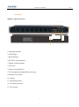
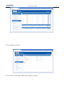
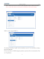
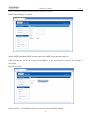
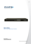
MS-PDU User Manual
MS-PDU
User Manual
1
V/0
MS-PDU User Manual
V/0
Contents
1. MS-PDU Summary .....................................................................................................................3
2. Main functions...........................................................................................................3
2.1 Monitor.... .................................................................................................................................3
2.2 Control .......................................................................................................................................3
2.3 Keep the former state of outlets after resetFOUT! BLADWIJZER NIET GEDEFINIEERD.
2.4 Self-defined alarm ...............................................FOUT! BLADWIJZER NIET GEDEFINIEERD.
2.5 System default alarm .........................................FOUT! BLADWIJZER NIET GEDEFINIEERD.
2.6 Alarm methods .....................................................FOUT! BLADWIJZER NIET GEDEFINIEERD.
2.7 User management ................................................FOUT! BLADWIJZER NIET GEDEFINIEERD.
2.8 Access method .......................................................FOUT! BLADWIJZER NIET GEDEFINIEERD.
3. Application .................................................... FOUT! BLADWIJZER NIET GEDEFINIEERD.
4.Product structure diagram .......................................................................................................5
5. Mounting method .........................................................................................................................6
6. Software instruction: ................................................................................................................6
6.1 Software summary...............................................................................................6
6.2 Access methods ........................................................................................................ .............. 6
6.2.1 Web access....................................................................................................11
6.2.2 SNMP Access................................................................................................13
6.2.3 Serial access..................................................................................................FOUT!
BLADWIJZER NIET GEDEFINIEERD.4
7.
Technical
parameters................................................................................................FOUT!
BLADWIJZER NIET GEDEFINIEERD.5
2
MS-PDU User Manual
V/0
MS-PDU User Manual
1. MS-PDU Summary:
On the trend of future power distribution management technology development, combining the
technology requirement of the modern data center application environment, adopting key technology
with fully independent intellectual property, the product is designed in combination of network
communication, power distribution and network management.
2.
Main functions
2.1 Monitor:total load current, on/off status of each outlet, temperature and humidity
2.2 Control: Switch on/off each outlet, set the delay of outlets sequential switching
2.3 Keep the former state of outlets after reset.
2.4 Self-defined alarm: set the threshold of total load current, temperature and humidity.
2.5 System default alarm: when threshold of total load current is exceeded; when threshold of
temperature and humidity is exceeded.
2.6 Alarm methods: buzzer alarm; red words alerts on web interface; Email alarm; SNMP trap
alarm.
2.7 User management: user name and password configurable.
2.8 Access method: Web based, access via IE; SNMP (v1); Serial access via command line control.
3.
Application
3.1 MS-PDU is applicable to server racks, network racks.
3.2 Outlet types and numbers are customized according to specific requirement.
3.3 MS-PDU is applicable to 110VAC/32A(16A), 220VAC/32A(16A).
3
MS-PDU User Manual
4. Product structure diagram
MS-PDU 1: Vertical Series
1
2
1. Mounting brackets
2. Wire terminal connection box
3. LED display
3
4. NET: Ethernet port
1
4
7
5
6
8
9
10
5. SER: serial port RS232
6. T/H: temperature & humidity sensor port
7. RUN: operation state indicator
11
8. STATUS: alarm indicator
12
13
9. RESET: reset button
10. BUTTON: selection button
11: outlets indicators
12: C14 plug locker
13: outlets/sockets
14: Mounting brackets
4
V/0
MS-PDU User Manual
V/0
14
MS-PDU 2: Horizontal Series
3
2
10
4
5
1
11
6
12
1. Mounting brackets
2. LED display
3. RUN indicator
4. STATUS: alarm indicator
5. Button: selection button
6. NET port
7. SER: serial port RS232
8. T/H: temperature and humidity sensor port
9. RESET: reset button
10. Outlets
11. Mounting brackets
12. Overload protection
13. Power input
5
7
8
9
13
MS-PDU User Manual
5.
V/0
Mounting method
Horizontal or Vertical installation.
6.
Software instruction
6.1 Software summary
MS-PDU is widely applied to the data centers of industries like network communication, telecom,
electric power, finance, insurance, aerospace, transportation, information processing, education,
medical, E-government etc.
6.2 Access methods
MS-PDU can be accessed via Web (support Internet Explorer, Google Chrome, Firefox), SNMP v1
and serial.
6.2.1 Web access
How to access the Web?
1. Connect one MS-PDU to the PC directly with the patch cable provided.
2. Check the IP of the PC, make sure it’s in the same network segment of the IP of MS-PDU (The
factory default IP is 192.168.1.161).
For example: change the IP of the PC to be 192.168.1.X (X can be 0 to 255 except 161)
3. Input the IP of the MS-PDU into the web browser and enter, the login window will pop up. The
default User name is niveo and Password is niveo. Main interface as below.
6
MS-PDU User Manual
V/0
Main interface includes 3 parts: company logo & product name, Device Manager and Server
Settings.
Device Manager has 3 sub menus, see below.
Device State: click it to the main interface displaying the on/off state of outlets and the state of
temperature and humidity.
Threshold Settings: to set the threshold of load ampere, temperature and humidity. See below.
7
MS-PDU User Manual
Device Settings: see below
Device Name: set the name of PDU (name length 1-16 digits)
8
V/0
MS-PDU User Manual
Output power on delay: set the interval of outlets sequential switching on (1-255s).
Output power off delay: set the interval of outlets sequential switching off (1-255s).
Web server port:fill in the port and save (1-65535).
Service Settings: see below
User Settings: set or modify the user name and password (Max. 16 digits)
Network: System IP:192.168.1.163(factory default IP)
Subnet Mask:255.255.255.0
Default Gateway:192.168.1.1
9
V/0
MS-PDU User Manual
V/0
DNS:default as 202.96.128.86. Please fill in the right DNS in order to make the email alert.
Note: a restart of the software is necessary after a modification of the network settings.
SNMP: see below (support SNMP v1)
The default get community is “public” and set community is “private”. User can modify according to
the specific application.
Fill in the trap address of SNMP management platform, trap alarm will be sent automatically. There
are 2 Trap addresses.
10
MS-PDU User Manual
V/0
Note: a software restart is necessary after a setting of SNMP.
Email Alarm Settings: see below
Set the SMTP including SMTP account, password, SMTP server and port and save.
Click Testing and fill in the testing email address. If the test email is received, the setting is
successful.
Restart: see below
Select Activity:to restart the software or restore to factory default settings.
11
MS-PDU User Manual
V/0
Note:1. Click RESET button, product will restart.
2.Click BUTTON and RESET at the same time, will restore the factory setting.
3.Buzzing will not alarm while restarting and restoring the factory setting.
6.2.2 SNMP Access
The software supports SNMP v1. A MIB file is provided with an enterprise number.
OID table as below.
Item
OID
Description
Device Name
1.3.6.1.4.1.30966.10.2.1.1
Name of the device
Read/Write
Device Type
1.3.6.1.4.1.30966.10.2.1.2
Type of the device
Read/Write
Output Num
1.3.6.1.4.1.30966.10.2.1.3
Number of outlets
Read
Input Voltage
1.3.6.1.4.1.30966.10.2.2.1
Input voltage
Read
Input Current
1.3.6.1.4.1.30966.10.2.2.2
Input ampere
Read
Output Current1
1.3.6.1.4.1.30966.10.2.3.1
Ampere of outlet No.1
Read
Output Current2
1.3.6.1.4.1.30966.10.2.3.2
Ampere of outlet No.2
Read
Output Current3
1.3.6.1.4.1.30966.10.2.3.3
Ampere of outlet No.3
Read
Output Current4
1.3.6.1.4.1.30966.10.2.3.4
Ampere of outlet No.4
Read
Output Current5
1.3.6.1.4.1.30966.10.2.3.5
Ampere of outlet No.5
Read
Output Current6
1.3.6.1.4.1.30966.10.2.3.6
Ampere of outlet No.6
Read
Output Current7
1.3.6.1.4.1.30966.10.2.3.7
Ampere of outlet No.7
Read
Output Current8
1.3.6.1.4.1.30966.10.2.3.8
Ampere of outlet No.8
Read
Output Current9
1.3.6.1.4.1.30966.10.2.3.9
Ampere of outlet No.9
Read
Output Current10
1.3.6.1.4.1.30966.10.2.3.10
Ampere of outlet No.10
Read
Output Current11
1.3.6.1.4.1.30966.10.2.3.11
Ampere of outlet No.11
Read
Output Current12
1.3.6.1.4.1.30966.10.2.3.12
Ampere of outlet No.12
Read
Output Current13
1.3.6.1.4.1.30966.10.2.3.13
Ampere of outlet No.13
Read
Output Current14
1.3.6.1.4.1.30966.10.2.3.14
Ampere of outlet No.14
Read
Output Current15
1.3.6.1.4.1.30966.10.2.3.15
Ampere of outlet No.15
Read
Output Current16
1.3.6.1.4.1.30966.10.2.3.16
Ampere of outlet No.16
Read
12
Mode
MS-PDU User Manual
V/0
Output Current17
1.3.6.1.4.1.30966.10.2.3.17
Ampere of outlet No.17
Read
Output Current18
1.3.6.1.4.1.30966.10.2.3.18
Ampere of outlet No.18
Read
Output Current19
1.3.6.1.4.1.30966.10.2.3.19
Ampere of outlet No.19
Read
Output Current20
1.3.6.1.4.1.30966.10.2.3.20
Ampere of outlet No.20
Read
Output Current21
1.3.6.1.4.1.30966.10.2.3.21
Ampere of outlet No.21
Read
Output Current22
1.3.6.1.4.1.30966.10.2.3.22
Ampere of outlet No.22
Read
Output Current23
1.3.6.1.4.1.30966.10.2.3.23
Ampere of outlet No.23
Read
Output Current24
1.3.6.1.4.1.30966.10.2.3.24
Ampere of outlet No.24
Read
Switch1
1.3.6.1.4.1.30966.10.2.4.1
On/off state of outlet No.1
Read/Write
Switch2
1.3.6.1.4.1.30966.10.2.4.2
On/off state of outlet No.2
Read/Write
Switch3
1.3.6.1.4.1.30966.10.2.4.3
On/off state of outlet No.3
Read/Write
Switch4
1.3.6.1.4.1.30966.10.2.4.4
On/off state of outlet No.4
Read/Write
Switch5
1.3.6.1.4.1.30966.10.2.4.5
On/off state of outlet No.5
Read/Write
Switch6
1.3.6.1.4.1.30966.10.2.4.6
On/off state of outlet No.6
Read/Write
Switch7
1.3.6.1.4.1.30966.10.2.4.7
On/off state of outlet No.7
Read/Write
Switch8
1.3.6.1.4.1.30966.10.2.4.8
On/off state of outlet No.8
Read/Write
Switch9
1.3.6.1.4.1.30966.10.2.4.9
On/off state of outlet No.9
Read/Write
Switch10
1.3.6.1.4.1.30966.10.2.4.10
On/off state of outlet No.10
Read/Write
Switch11
1.3.6.1.4.1.30966.10.2.4.11
On/off state of outlet No.11
Read/Write
Switch12
1.3.6.1.4.1.30966.10.2.4.12
On/off state of outlet No.12
Read/Write
Switch13
1.3.6.1.4.1.30966.10.2.4.13
On/off state of outlet No.13
Read/Write
Switch14
1.3.6.1.4.1.30966.10.2.4.14
On/off state of outlet No.14
Read/Write
Switch15
1.3.6.1.4.1.30966.10.2.4.15
On/off state of outlet No.15
Read/Write
Switch16
1.3.6.1.4.1.30966.10.2.4.16
On/off state of outlet No.16
Read/Write
Switch17
1.3.6.1.4.1.30966.10.2.4.17
On/off state of outlet No.17
Read/Write
Switch18
1.3.6.1.4.1.30966.10.2.4.18
On/off state of outlet No.18
Read/Write
Switch19
1.3.6.1.4.1.30966.10.2.4.19
On/off state of outlet No.19
Read/Write
Switch20
1.3.6.1.4.1.30966.10.2.4.20
On/off state of outlet No.20
Read/Write
Switch21
1.3.6.1.4.1.30966.10.2.4.21
On/off state of outlet No.21
Read/Write
13
MS-PDU User Manual
V/0
Switch22
1.3.6.1.4.1.30966.10.2.4.22
On/off state of outlet No.22
Read/Write
Switch23
1.3.6.1.4.1.30966.10.2.4.23
On/off state of outlet No.23
Read/Write
Switch24
1.3.6.1.4.1.30966.10.2.4.24
On/off state of outlet No.24
Read/Write
6.2.3 Serial access
Baud rate is 9600.
There are 5 commands: OUTPUT, INPUT, SWITCH, RESET and REBOOT.
OUTPUT command:OUTPUT X
For example: send command OUTPUT 1, get output 1 current: X A.
INPUT command: INPUT X (1 is voltage, 2 is current)
For example: send command INPUT 1, get total voltage: X V
send command INPUT 2, get total current: X A
SWITCH command: SWITCH X
For example: send command SWITCH 1, get the on/off state of output 1.
RESET command: to reset to factory default configuration.
REBOOT command: to reset the PDU
7.
Technical parameters
No
1
2
Item
Input
Parameters
Rated input voltage
110/220V~ 0/60 Hz
Input plug
Standard: IEC60309 plug
Cable
16A:3×2.5mm², 32A:3×6.0mm²
Max. load
16A, 32A
Overload protection
Master circuit breaker 1P
Rated output voltage
110/220VAC
Max. load
16A, 32A
Output
Standard: IEC320 C13
Outlet types
Other sockets optional
3
Outlet numbers
Optional
NET port
1 x RJ45
Serial port
1 x RJ45
Ports
14
MS-PDU User Manual
Temperature/humidity
1 x RJ11
sensor port
4
Operation state
1 x LED
Error state
1 x LED
Display
Full scale:32A/16A
Total ampere
5
Accuracy:±1﹪+ 0.2
Resolution:200mA; Response:400ms
Digital
ammeter
Full scale:25A
Individual ampere
Accuracy:±1﹪+0.1
Resolution:100mA ; Response:400ms
Working condition:-40℃~+100℃,
Temperature
Accuracy:±1℃; Response:4s
6
Accuracy:±5﹪RH
Humidity
Response:400ms
7
Dimension
L×W ×H
X2×66.6×44.4mm
8
Case
Color
Black
Mounting brackets
2pcs
Ethernet wire
2M, blue
Serial wire
2M, yellow
User Manual
1 x CD
Sensor
Temperature & humidity sensor
Working condition
0℃~55℃
Relative humidity
10~90%
Storage
-20℃ ~ +70℃
9
Fittings
Optional
10
fitting
11
12
Environment
ROHS
YES
15
V/0