1
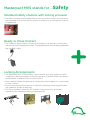
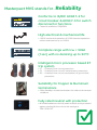
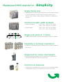
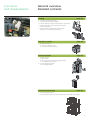
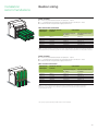
Masterpact MVS LV power circuit breakers & switch disconnectors 800 to 3200A Catalogue 2010 Schneider Electric The global specialist in energy management Schneider Electric, the undisputed global leader in Power Circuit Breakers Ever since the launch of first circuit breaker in 1923 > At forefront in developing products with cutting-edge technology > Masterpact NT/NW Power Circuit Breakers with integrated metering, communication capabilities & high performance levels have set new standards around the world > We also understand the optimum needs of our customers and we continue to innovate Inheriting the key values of Masterpact Family Safety, Reliability and Simplicity, now we introduce 1 Masterpact MVS from 800 to 3200A Masterpact Value System >Single frame size for complete range >Icu=Ics=Icw (1sec)=50kA >Microprocessor based ET trip system 2 Safety Reliability Simplicity Masterpact MVS stands for... Safety Reliability Simplicity 3 4 Masterpact MVS stands for Safety Standard safety shutters with locking provision > the safety shutters automatically block access to contact clusters & no live parts are accessible. The shutter-locking system is made up of a moving block that can be padlocked. Ready to Close Contact > The "ready to close" position of the circuit breaker is indicated by a mechanical indicator and a PF changeover contact. This signal indicates that all safety parameters are full-filled & valid. Locking Arrangements > The positive locking of connected, disconnected and test positions is built in feature in draw-out breakers & the exact position is obtained when the racking handle blocks. A release button is used to free it. > Door interlock inhibits the opening of cubicle door when breaker is in connected or test position. > Push button locking, blocks access to ON/OFF pushbuttons and may be locked with padlocks, screws or lead seal. > The circuit breaker is locked in OFF position using key locks by physically maintaining the opening pushbutton pressed down. 5 6 Masterpact MVS stands for Reliability Conforms to IS/IEC 60947-2 for circuit breaker & 60947-3 for switch disconnector functions. > Tested & certified at CPRI/ERDA High electrical & mechanical life > 10000 mechanical operations & 5000 electrical operations without maintenance up to 1600A Complete range with Icw = 50kA (1sec) with no derating up to 50°C Intelligent micro processor based ET trip system > 2I - Overload, Short-circuit protections > 5S - Overload, Short-circuit & Instantaneous protections > 6G - Overload, Short-circuit ,Instantaneous & ground-fault protections Suitability for Copper & Aluminium terminations > Offers flexibility in busbar terminations for Indian environmental conditions Fully rated neutral with protection > All 4Pole breakers are with fully rated neutral & can be protected against overload & short-circuit with settings at 50%-100%-OFF 7 8 Masterpact MVS stands for Simplicity Single frame size > Masterpact MVS offers single frame size for the complete range of circuit breakers & switch dis-connector versions up to 3200A which helps in faster design & delivery of distribution systems. Common height, width & depth > Draw out breaker > Fixed breaker - 439 x 441 x 395mm for 3Pole 439 x 556 x 395mm for 4Pole 352 x 422 x 297mm for 3Pole 352 x 537 x 297mm for 4Pole Single pole pitch of 115mm > Enables termination of aluminium/copper busbars or cables. Flexibility in terminal orientation > Simply turn a horizontal rear connector 90° to make it a vertical connector. Single bolt for motor mechanism > Manual operated breaker can be converted in to Electrical breaker at installation with less down time. Common accessories > Accessories & auxiliaries are common for the complete range of Masterpact family, thus reducing the inventory costs. 9 10 Environmentally responsible > Masterpact MVS is part of Schneider Electrics energy efficiency approach. Designed for easy disassembly and recycling at end of life, Masterpact MVS complies with environmental directives RoHS* and WEEE**, and with ISO 14001 standards, thanks to non-polluting factories. Schneider Electric fully takes into account environmental requirements, starting right from the design phase of every product through to the end of its service life: @ the materials used for Masterpact MVS are not potentially dangerous to the environment @ the production facilities are non-polluting in compliance with the ISO 14001standard @ the energy dissipated per pole is low, making energy losses insignificant @ the materials are marked to facilitate sorting for recycling at the end of product service life. Secondary raw materials Plastic Copper Iron & Steel Masterpactpact MVS power circuit breakers and accessories can be recycled and reused optimally. Decomposition Energy resources Recyling Center * RoHS = Restriction of Hazardous Substances ** WEEE = Waste Electrical and Electronic Equipment 11 12 Ideal for a variety of Applications Energy & infrastructure Industry Buildings Residential 13 14 Masterpact MVS 800 to 3200 A Masterpact MVS Benefits for every customer Panel builders / Contractors > Single frame size from 800A-3200A with identical door cut-outs > Suitable for Copper & Aluminium termination with a single pole pitch of 115mm. > Terminal orientation can be converted from horizontal to vertical and vice-versa at workshop > Direct mounting Door frames (Escutcheon) without drilling any holes. > Front fitted accessories like Under-volt release, shunt release & closing coil for complete range. > Conversion of manual operated breaker in to electrical operated, with single bolt fixing Masterpact MVS with single frame size, common accessories helps to increase the shop floor efficiency, enabling faster delivery of switch boards End Users > > > > > > Moulded case design ensures high endurance without maintenance Intelligent Microprocessor based trip units with thermal memory Overload run alarm & individual LED indications enable fault identification Icu=Ics=Icw(1sec)=50kA ensures complete selectivity Inbuilt safety shutter & interlocks Ready-to-close contact signal indicates that all safety parameters are fullfilled & valid. > No derating up to 50°C > All 4Pole breakers are with fully rated neutral with adjustable protections at OFF-50%-100% Masterpact MVS answers even to the most stringent application with most reliable distribution systems assuring continuity of service. Designers er V orm 15 nsf / 4 Tra 1 kV 1 > Conforms to IS/IEC 60947-2 for breakers & IS/IEC60947-3 for disconnectors > Intelligent Microprocessor based trip units with overload, short circuit & earth fault protections with in-built thermal memory > Icu=Ics=Icw(1sec) =50kA > Typical design of shunt coil & closing coil helps in simple interlocking schemes > Ready-to-close contacts ensures safety parameters are full-filled enabling closure of breaker. > Masterpact MVS respects the environment throughout their life cycle Masterpact MVS is the answer to the needs of your customers with flexibility to modify system design during the design phase 15 Functions and characteristics General overview Detailed contents Circuit breakers and switch-disconnectors 1. 2. 3. 4. 5. page 18 ratings: Masterpact MVS 800 to 3200 A circuit breakers type N switch-disconnectors type NA 3 or 4 poles fixed or drawout versions Microprocessor based ET Trip System page 20 2I : basic protection 5S : selective protection 6G : selective + earth-fault protection Microprocessor based ET2I Trip System Microprocessor based ET5S Trip System Connections page 25 rear connection (horizontal or vertical) Horizontal 16 Microprocessor based ET6G Trip System Vertical Functions and characteristics General overview Detailed contents Locking page 26 1. 2. 3. 4. ON/OFF Pushbutton locking OFF-position locking by keylock chassis locking in disconnected position by keylock chassis locking in connected, disconnected and test positions 5. door interlock (inhibits door opening with breaker in connected/test position) Indication contacts page 28 1. standard contacts: a. ON/OFF indication (OF) b. "fault trip" indication (SDE) Remote operation page 29 1. remote ON/OFF: a. gear motor b. XF closing or MX opening voltage releases c. PF ready-to-close contact 2. remote tripping function: a. MN voltage release Mechanical interlocking page 32 1. two Masterpact MVS or 2. three Masterpact MVS can be mechanically interlocked using cables 17 Functions and characteristics Circuit breakers and switch-disconnectors MVS08 to MVS32 Common characteristics Number of poles Rated insulation voltage (V) Impulse withstand voltage (kV) Rated operational voltage (V AC 50/60 Hz) Suitability for isolation Degree of pollution Ui Uimp Ue IEC 60947-2 IEC 60664-1 3/4 1000 12 440 Yes 4 Basic circuit-breaker Circuit-breaker as per IEC 60947-2 Rated current (A) at 50 °C Rating of 4th pole (A) Ultimate breaking capacity (kA rms) V AC 50/60 Hz Rated service breaking capacity (kA rms) Rated short-time withstand current (kA rms) V AC 50/60 Hz Rated making capacity (kA peak) V AC 50/60 Hz Utilisation category Closing time Opening time In Icu Ics Icw 1s 3s Icm (ms) (ms) Switch-disconnector according to IEC 60947-3 Rated making capacity (kA peak) Icm AC23 category V AC 50/60 Hz Rated short-time withstand current (kA rms) Icw AC23 category V AC 50/60 Hz 1s Installation/connection/maintenance Service life C/O cycles x 1000 Connection Dimension (mm) (H x W x D) Weight (kg) (1) 3200A: with vertical connections for drawout type circuit breaker 18 Mechanical Electrical with maintenance without maintenance without maintenance Horizontal Vertical Drawout 3P 4P Fixed 3P 4P Drawout 3P/4P Fixed 3P/4P Functions and characteristics Circuit breakers and switch-disconnectors MVS08 to MVS32 MVS08 N 800 800 MVS10 N 1000 1000 MVS12 N 1250 1250 MVS16 N 1600 1600 MVS20 N 2000 2000 MVS25 N 2500 2500 MVS32 N 3200(1) 3200 50 50 50 50 50 50 50 50 50 50 50 50 50 50 50 35 50 35 50 35 50 35 50 35 50 35 50 35 105 105 105 105 105 105 105 MVS08 NA MVS10 NA MVS12 NA MVS16 NA MVS20 NA MVS25 NA MVS32 NA 105 105 105 105 105 105 105 50 50 50 50 50 50 50 B <70 <40 20 10 5 Yes Yes 439 x 441 x 395 439 x 556 x 395 352 x 422 x 297 352 x 537 x 297 78/95 42/52 16 8 3 19 Functions and characteristics Identifying Microprocessor based ET Trip System Designations Microprocessor based ET2I Trip System: basic protection All Masterpact MVS Air Circuit Breakers are equipped with an Microprocessor based ET Trip System. Microprocessor based ET Trip Systems are designed to protect power circuits and connected loads Long time + Instantaneous Microprocessor based ET5S Trip System: selective protection Long time + Short time + Instantaneous Microprocessor based ET6G Trip System: selective + ground-fault protection Long time + Short time + Instantaneous 20 Ground-fault protection Functions and characteristics Presentation Microprocessor based ET Trip System description 1. top fastener 2. bottom fastener 3. protective cover 4. cover opening point 5. lead-seal fixture for protective cover 6. long-time rating plug 7. screw for long-time rating plug 8. connection with circuit breaker 9. long-time trip indicator light 10. short-time or instantaneous trip indicator light 11. self-protection indicator light 12. reset button for battery status check and trip indicator LED 13. ground-fault trip indicator light Adjustment dials 14. long-time current setting Ir 15. long-time tripping delay tr 16. short-time pickup Isd 17. short-time tripping delay tsd 18. instantaneous pick-up Ii 19. LED indicating an overload-alarm 20. ground-fault pick-up Ig 21. ground-fault tripping delay tg Test 22. test button for ground-fault 23. test connector Microprocessor based ET2I Trip System Microprocessor based ET6G Trip System Microprocessor based ET5S Trip System 21 Functions and characteristics Overview of functions Current protection Protection settings Depending on the type of installation, it is possible to set the tripping curve of your control unit using the parameters presented below. Microprocessor based ET2I Trip System Microprocessor based ET5S/6G Trip System Microprocessor based ET6G Trip System 1. current setting Ir (long time) 2. tripping delay tr (long time) for 6 x Ir 3. pick-up Isd (instantaneous) 1. current setting Ir (long time) 2. tripping delay tr (long time) for 6 x Ir 3. pick-up Isd (short time) 4. tripping delay tsd (short time) 5. pick-up Ii (instantaneous) 1. pick-up Ig (ground fault) 2. tripping delay tg (ground fault) Long-time protection The long-time protection function protects cables (phases and neutral) against overloads. This function is based on true rms measurements. Thermal memory The thermal memory continuously accounts for the amount of heat in the cables, both before and after tripping, whatever the value of the current (presence of an overload or not). The thermal memory optimises the long-time protection function of the circuit breaker by taking into account the temperature rise in the cables. The thermal memory assumes a cable cooling time of approximately 15 minutes. Long-time current setting Ir and standard tripping delay tr ET Trip System Accuracy 2l, 5S and 6G Current setting (A) Ir = In (*) x ... 0.4 0.5 0.6 0.7 0.8 0.9 0.95 0.98 1 0.5 1 2 4 8 12 16 20 24 12.5 0.7 (1) 0.7 (2) 25 1 0.69 50 2 1.38 100 4 2.7 200 8 5.5 300 12 8.3 400 16 11 500 20 13.8 600 24 16.6 tripping between 1.05 and 1.20 Ir time setting (s) time delay (s) tr at 1.5 x Ir 0 to -30% tr at 6 x Ir 0 to -20% tr at 7.2 x Ir 0 to -20% (*) In: circuit breaker rating (1) 0 to -40% (2) 0 to -60% Overload LED This LED signals that the long-time current setting Ir has been overrun. 22 Functions and characteristics Overview of functions Current protection Short-time protection 1. 2. 3. 4. the short-time protection function protects the distribution system against impedant short-circuits. the short-time tripping delay can be used to ensure discrimination with a downstream circuit breaker. the I2t ON and I2t OFF options enhance discrimination with downstream protection devices. use of I2t curves with short-time protection: a. I2t OFF selected: the protection function implements a constant time curve b. I2t ON selected: the protection function implements an I2t inverse-time curve up to 10 Ir. Above 10 Ir, the time curve is constant. Short-time pick-up Isd and tripping delay tsd Microprocessor based ET Trip System pick-up (A) Isd = Ir x ... accuracy ± 10% 5S and 6G time delay (ms) at 10 Ir l2t Off or l2t On 20 80 time setting tsd (s) l2t Off l2t On tsd (max resettable time) tsd (max break time) 1.5 0 2 0.1 0.1 80 140 2.5 0.2 0.2 140 200 3 0.3 0.3 230 320 4 0.4 0.4 350 500 5 6 8 10 Instantaneous protection the instantaneous-protection function protects the distribution system against solid short-circuits. Contrary to the short-time protection function, the tripping delay for instantaneous protection is not adjustable. The tripping order is sent to the circuit breaker as soon as current exceeds the set value, with a fixed time delay of 20 milliseconds. Instantaneous pick-up Isd Microprocessor based ET Trip System pick-up (A) Isd = Ir x ... accuracy ± 10% time delay (ms) (max resettable time) (max break time) 2I 1.5 20 80 2 2.5 3 4 5 6 8 10 4 6 20 50 * In: circuit-breaker rating 8 10 12 15 off Instantaneous pick-up li Microprocessor based ET Trip System 5S and 6G pick-up (A) li = In (*) x... accuracy ± 10% 2 3 time delay (ms) (max resettable time) (max break time) Protection of the fourth pole on four-pole circuit breakers Type of neutral Description. Neutral protection at In The cross-sectional area of the neutral conductor is equal to that of the phase conductors. 1. the long-time current setting Ir for the neutral is equal to the setting value 2. the short-time pick-up Isd for the neutral is equal to the setting value 3. the instantaneous pick-up Isd and Ii for the neutral are equal to the setting value. Neutral protection for three-pole devices Neutral protection is not available on three-pole devices. Ground-fault protection on ET6G Trip System an ground fault in the protection conductors can provoke local temperature rise at the site of the fault or in the conductors. The purpose of the ground-fault protection function is to eliminate this type of fault. Type Description Residual 1. the function determines the zero-phase sequence current, i.e. the vectorial sum of the phase and neutral currents 2. it detects faults downstream of the circuit breaker. 23 Functions and characteristics Microprocessor based ET Trip System Accessories and test equipment Ground-fault pick-up Ig and tripping delay tg The pick-up and tripping-delay values can be set independently. 1. ground-fault and neutral protection are independent and can therefore be combined. 2. ground-fault protection in 3P+N system is activated by installing a external sensor(CT) in the neutral conductor and connecting to Microprocessor based ET Trip System. Microprocessor based ET Trip System 6G pick-up (A) Ig = In (*) x accuracy ± 10 % A In 1200 A In > 1200 A time setting tg (s) time delay (ms) at 10 In (*) tg (max resettable time) l2t Off or l2t On tg (max break time) B C 0.3 0.4 640 720 0.1 0.2 0.1 0.2 20 80 140 80 140 200 * In: circuit-breaker rating 0.2 500 0 D 0.5 800 0.3 0.3 230 320 E 0.6 880 0.4 0.4 350 500 F 0.7 960 G 0.8 1040 H 0.9 1120 I 1 1200 External sensors (Neutral CT) External sensor for earth-fault and neutral protection The sensors, used with the 3P circuit breakers, are installed on the neutral conductor for: 1. residual type earth-fault protection(with Microprocessor based ET Trip System) The rating of the sensor (CT) must be compatible with the rating of the circuit breaker: (i) MVS08 to MVS20: CT 400/2000 (ii) MVS25 to MVS32: CT 1000/3200 External sensor (CT). Hand-held test kit (HHTK) The hand-held mini test kit may be used to: check operation of the control unit and the tripping and pole-opening system by sending a signal simulating a short-circuit. Power source: standard LR6-AA battery. 24 Functions and characteristics Two types of connection are available: 1.vertical rear connection. 2.horizontal rear connection. The solutions presented are similar in principle for all Masterpact MVS fixed and drawout devices. Connections Overview of solutions Rear connection Horizontal Vertical Simply turn a horizontal rear connector 90° to make it a vertical connector. Note: Masterpact circuit breakers can be connected indifferently with bare-copper, tinned-copper and tinned-aluminium conductors, requiring no particular treatment 25 Functions and characteristics Locking On the device Access to pushbuttons protected by transparent cover. Pushbutton locking The transparent cover blocks access to the pushbuttons used to open and close the device. It is possible to independently lock the opening button and the closing button. The locking device is often combined with a remote operating mechanism. The pushbuttons may be locked using either: 1. three padlocks (not supplied) 2. lead seal 3. two screws. Pushbutton locking using a padlock. Device locking in the OFF position using key lock The circuit breaker is locked in the OFF position by physically maintaining the opening pushbutton pressed down: using keylocks (one or two different keylocks, supplied). Keys may be removed only when locking is effective (Profalux or Ronis type locks). The keylocks are available in any of the following configurations: 1. one keylock 2. two identical key locks - one keylock mounted on the device + one identical keylock supplied separately for interlocking with another device Breaker front cover with keylocks option. PROFAULX RONIS OFF position locking using a keylock. 26 Functions and characteristics Locking On the chassis "Disconnected" position locking Mounted on the chassis and accessible with the door closed, these devices lock the circuit breaker in the "disconnected" position in two manners: 1. using padlocks (standard), up to three padlocks (not supplied) 2. using keylocks (optional), one or two different keylocks are available. Profalux and Ronis keylocks are available in different options: 1. one keylock 2. two identical key locks - one keylock mounted on the device + one identical keylock supplied separately for interlocking with another device. A locking kit (without locks) is available for installation of one or two keylocks (Ronis, Profalux). "Connected", "disconnected" and "test" position locking 1 Padlock locking. Door interlock 3 2 Keylock locking The "connected", "disconnected" and "test" positions are shown by an indicator. The exact position is obtained when the racking handle blocks. A release button is used to free it. Padlock Circuit breaker in "disconnected" position. Pull out the tab. Insert the shackle (max. diameter 5 to 8 mm) of the padlock(s). The crank cannot be inserted. Keylock Circuit breaker in "disconnected" position. Turn the key(s). Remove the key(s) The crank cannot be inserted. Door interlock catch Mounted on the right hand side of the chassis, this device inhibits opening of the cubicle door when the circuit breaker is in "connected" or "test" position. If the breaker is put in the "connected" position with the door open, the door may be closed without having to disconnect the circuit breaker. Door interlock catch 27 Functions and characteristics Indication contacts ON/OFF indication contacts (OF) This type of contacts indicate the ON or OFF position of the circuit breaker: 1. rotary type changeover contacts directly driven by the mechanism for Masterpact MVS. These contacts trip when the minimum isolation distance between the main circuit-breaker contacts is reached. OF ON/OFF indication contacts - (OF) (rotary type). MVS Supplied as standard Maximum number Breaking capacity (A) Standard p.f.: 0.3 V AC 240/380 AC12/DC12 V DC 125 (1) Standard contacts: 10 A; optional contacts: 6 A. 4 8 Minimum load: 100 mA/24 V 10/6 (1) 10/6 (1) "Fault-trip" indication contacts (SDE) Circuit-breaker tripping due to a fault is signalled by: 1. a red mechanical fault indicator (reset) 2. one changeover contact (SDE). Following tripping, the mechanical indicator must be reset before the circuit breaker may be closed. One SDE is supplied as standard. SDE Supplied as standard Breaking capacity (A) p.f.: 0.3 AC12/DC12 MVS Standard V AC 240/380 V DC 125 1 Minimum load: 100 mA/24 V 5 0.3 "Connected", "disconnected" and "test" position carriage switches Three series of optional auxiliary contacts are available for the chassis: 1. changeover contacts to indicate the "connected" position (CE) 2. changeover contacts to indicate the "disconnected" position (CD). This position is indicated when the required clearance for isolation of the power and auxiliary circuits is reached 3. changeover contacts to indicate the "test" position (CT). In this position, the power circuits are disconnected and the auxiliary circuits are connected. CE, CD and CT "connected/disconnected/test" position carriage switches. 28 MVS Contacts Maximum number Breaking capacity (A) p.f.: 0.3 AC12/DC12 Standard V AC 240/380 V DC 125 CE/CD/CT 3 3 3 Minimum load: 100 mA/24 V 8 0.8 Functions and characteristics a point-to-point solution for remote operation of Masterpact MVS: Remote operation Remote ON / OFF The remote ON / OFF function is used to remotely open and close the circuit breaker. It is made up of: 1. an electric motor (MCH) equipped with a "spring charged" limit switch contact (CH) 2. two voltage releases: a a closing release (XF) b an opening release (MX) Optionally, other functions may be added: 1. PF ready-to-close contact A remote-operation function is generally combined with: 1. device ON / OFF indication (OF) 2. "fault-trip" indication (SDE) Wiring diagram of a point-to-point remote ON / OFF function Note: an opening order always takes priority over a closing order. If opening and closing orders occur simultaneously, the mechanism discharges without any movement of the main contacts. The circuit breaker remains in the open position (OFF). In the event of maintained opening and closing orders, the standard mechanism provides an anti-pumping function by blocking the main contacts in open position. Anti-pumping function: After fault tripping or intentional opening using the manual or electrical controls, the closing order must first be discontinued, then reactivated to close the circuit breaker. 29 Functions and characteristics Remote operation Remote ON / OFF Electric motor (MCH) The electric motor automatically charges and recharges the spring mechanism when the circuit breaker is closed. Instantaneous reclosing of the breaker is thus possible following opening. The spring-mechanism charging handle is used only as a backup if auxiliary power is absent. The electric motor (MCH) is equipped as standard with a limit switch contact (CH) that signals the "charged" position of the mechanism (springs charged). Characteristics Power supply V AC 50/60 Hz V DC Operating threshold Consumption (VA or W) Motor overcurrent Charging time Operating frequency CH contact 100/130, 200/240 ,380/415 24/30, 48/60, 100/125, 200/250 0.85 to 1.1 Un 180 2 to 3 In for 0.1 s maximum 4 s for Masterpact MVS maximum 3 cycles per minute 10 A at 240 V Electric motor (MCH) for Masterpact MVS. Voltage releases (XF and MX) Closing release (XF) The XF release remotely closes the circuit breaker if the spring mechanism is charged. Opening release (MX) The MX release instantaneously opens the circuit breaker when energised. It locks the circuit breaker in OFF position if the order is maintained. XF and MX voltage releases. Characteristics XF MX Power supply V AC 50/60 Hz V DC 0.85 to 1.1 Un Hold: 4.5 100/130, 200/250, 380/480 24/30, 48/60, 100/130, 200/250 0.7 to 1.1 Un Hold: 4.5 Pick-up: 200 (200 ms) Pick-up: 200 (200 ms) 70 ms ±10 Operating threshold Consumption (VA or W) Circuit-breaker response time at Un 30 Functions and characteristics Remote operation Remote ON / OFF Instantaneous voltage releases (MN) remote-tripping function Opening order D2 MN D1 MN Voltage release The MN release instantaneously opens the circuit breaker when its supply voltage drops to a value between 35 % and 70 % of its rated voltage. If there is no supply on the release, it is impossible to close the circuit breaker, either manually or electrically. Any attempt to close the circuit breaker has no effect on the main contacts. Circuit breaker closing is enabled again when the supply voltage of the release returns to 85 % of its rated value. Characteristics Power supply V AC 50/60 Hz V DC Operating threshold Opening Closing Consumption (VA or W) Circuit-breaker response time at Un 100/130, 200/250,380/480 24/30, 48/60 0.35 to 0.7 Un 0.85 Un Pick-up: 200 (200 ms) Hold: 4.5 90 ms ±5 MN delay units To eliminate circuit-breaker nuisance tripping during short voltage dips, operation of the MN release can be delayed. This function is achieved by adding an external delay unit in the MN voltage-release circuit. Two versions are available, adjustable and non-adjustable. Characteristics Power supply V AC 50-60 Hz /DC Operating threshold Non-adjustable 100/130 - 200/250 Adjustable 48/60 - 100/130 - 200/250 - 380/480 Opening 0.35 to 0.7 Un Closing 0.85 Un Delay unit consumption Pick-up: 200 (200 ms) Hold: 4.5 Circuit-breaker response time at Un Non-adjustable 0.25 s Adjustable 0.5 s - 0.9 s - 1.5 s - 3 s "Ready to close" contact (PF) The "ready to close" position of the circuit breaker is indicated by a mechanical indicator and a PF changeover contact. This signal indicates that all the following are valid: 1. the circuit breaker is in the OFF position 2. the spring mechanism is charged 3. a maintained opening order is not present: a. MX energised b. fault trip c. remote tripping (MN) d. device not completely racked in e. device interlocked with a second device. "Ready to close" contacts (PF). Characteristics MVS Maximum number 1 Breaking capacity (A) Standard Minimum load: 100 mA/24 V p.f.: 0.3 V AC 240/380 5 AC12/DC12 V DC 125 0.3 31 Functions and characteristics Mechanical interlocking Interlocking of two Masterpact MVS or up to three Masterpact MVS devices using cables For cable interlocking, the circuit breakers may be mounted one above the other or side-by-side. The interlocked devices may be fixed or drawout, three-pole or fourpole, and have different ratings and sizes. Interlocking between two devices This function requires: 1. an adaptation fixture on the right side of each device 2. a set of cables with no-slip adjustments. The maximum distance between the fixing planes (vertical or horizontal) is 2000mm. Interlocking between three devices This function requires: 1. a specific adaptation fixture for each type of interlocking, installed on the right side of each device 2. two or three sets of cables with no-slip adjustments. The maximum distance between the fixing planes (vertical or horizontal) is 1000 mm. Installation The adaptation fixtures, sets of cables and circuit breakers or switch-disconnectors are supplied separately, ready for assembly by the customer. Installation conditions for cable interlocking systems: 1. cable length: 2.5 m 2. radius of curvature: 100 mm 3. maximum number of curves: 3 32 Dimensions and connection MVS08 to MVS32 circuit breakers Fixed 3/4-poles device Dimensions Mounting on base plate or rails Mounting detail Safety clearances Door cutout A B Insulated Metal Energised (1) Without escutcheon (2) With escutcheon 0 0 0 0 100 60 Note: X and Y are the symmetry planes for a 3-pole device A(*) an overhead clearance of 110 mm is required to remove the arc chutes F : datum. 33 Dimensions and connection Connections MVS08 to MVS32 circuit breakers Fixed 3/4-poles device Horizontal rear connection Detail Vertical rear connection Detail Note: recommended connection screws: M10 class8.8. Tightening torque: 50 Nm with contact washer 34 Dimensions and connection MVS08 to MVS32 circuit breaker Drawout 3/4-poles device Dimensions Mounting on base plate or rails Mounting detail Safety clearances Door cutout A B Insulated Metal Energised 0 0 0 0 0 60 (1) Without escutcheon (2) With escutcheon Note: X and Y are the symmetry planes for a 3-pole device F : datum. 35 Dimensions and connection Connections Horizontal rear connection Vertical rear connection Note: recommended connection screws: M10 class8.8. Tightening torque: 50 Nm with contact washer. 36 MVS08 to MVS32 circuit breaker Drawout 3/4-poles device Detail Detail Installation recommendations Operating conditions Ambient temperature Masterpact MVS devices can operate under the following temperature conditions: 1. the electrical and mechanical characteristics are stipulated for an ambient temperature of -5° C to +60° C 2. circuit-breaker closing is guaranteed down to -15° C 3. Masterpact MVS (without ET Trip System) can be stored in an ambient temperature of -20° C to +85° C Electromagnetic disturbances Masterpact MVS devices are protected against: 1. overvoltages caused by devices that generate electromagnetic disturbances 2. overvoltages caused by an atmospheric disturbances or by a distributionsystem outage (e.g. failure of a lighting system) 3. devices emitting radio waves (radios, walkie-talkies, radar, etc.) 4. electrostatic discharges produced by users. Masterpact MVS devices have successfully passed the electromagneticcompatibility tests (EMC) defined by the following international standards: IEC 60947-2, appendix F The above tests guarantee that: 1. no nuisance tripping occurs 2. tripping times are respected. 37 Installation recommendations Installation in switchboard Possible positions Power supply Masterpact devices can be supplied either from the top or from the bottom without reduction in performance, in order to facilitate connection when installed in a switchboard. Mounting the circuit-breaker It is important to distribute the weight of the device uniformily over a rigid mounting surface such as rails or a base plate. This mounting plane should be perfectly flat (tolerance on support flatness: 2 mm). This eliminates any risk of deformation which could interfere with correct operation of the circuit breaker. Mounting on rails. 38 Installation recommendations Installation in switchboard Partitions Sufficient openings must be provided in partitions to ensure good air circulation around the circuit breaker; Any partition between upstream and downstream connections of the device must be made of non magnetic material. Busbars The mechanical connection must be exclude the possibility of formation of a magnetic loop around a conductor. 39 Installation recommendations Door interlock catch Door interlock Mounted on the right hand side of the chassis, this device inhibits opening of the cubicle door when the circuit breaker is in "connected" or "test" position. If the breaker is put in the "connected" position with the door open, the door may be closed without having to disconnect the circuit breaker. Dimensions (mm) Type MVS08-32 (3P) MVS08-32 (4P) (1) (2) 215 330 215 215 (1) (2) 83 103 Breaker in "connected" or "test" position Door cannot be opened Dimensions (mm) Type MVS Breaker in "disconnected" position Door can be opened Note: the door interlock can be mounted on the right side of the breaker. F : datum. 40 Installation recommendations Power connection Cables connections If cables are used for the power connections, make sure that they do not apply excessive mechanical forces to the circuit breaker terminals. For this, make the connections as follows: 1. extend the circuit breaker terminals using short bars designed and installed according to the recommendations for bar-type power connections: a. for a single cable, use solution B opposite b. for multiple cables, use solution C opposite 2. in all cases, follow the general rules for connections to busbars: a. position the cable lugs before inserting the bolts b. the cables should firmly secured to the framework E. Busbars connections The busbars should be suitably adjusted to ensure that the connection points are positioned on the terminals before the bolts are inserted (B). The connections are held by the support which is solidly fixed to the framework of the switchboard, such that the circuit breaker terminals do not have to support its weight C. (This support should be placed close to the terminals). Electrodynamic stresses The first busbar support or spacer shall be situated within a maximum distance from the connection point of the breaker (see table below). This distance must be respected so that the connection can withstand the electrodynamic stresses between phases in the event of a short circuit. Maximum distance A between busbar to circuit breaker connection and the first busbar support or spacer with respect to the value of the prospective short-circuit current. Ics (kA) Distance A (mm) 50 300 41 Installation recommendations Power connection Clamping Correct clamping of busbars depends amongst other things, on the tightening torques used for the nuts and bolts. Over-tightening may have the same consequences as under-tightening. For connecting busbars (Cu ETP-NFA51-100) to the circuit breaker, the tightening torques to be used are shown in the table below. These values are for use with copper busbars and steel nuts and bolts, class 8.8. The same torques can be used with AGS-T52 quality aluminium bars (French standard NFA 02-104 or American National Standard H-35-1). Examples 1. 2. 3. 4. 5. 6. Terminal screw factory-tightened to 16 Nm. Breaker terminal. Busbar. Bolt. Washer. Nut. Tightening torques Ø (mm) Nominal Ø (mm) Drilling 10 11 Tightening torques (Nm) Tightening torques (Nm) with grower or flat washers with contact or corrugatec washers 37.5 50 Busbar drilling Examples Isolation distance Dimensions (mm) Ui 600 V 1000 V X (min) 8 mm 14 mm Busbar bending When bending busbars maintain the radius indicated below(a smaller radius would cause cracks). Dimensions (mm) e Radius of curvature r (min) 5 5 10 15 42 Recommended 7.5 18 to 20 Installation recommendations Busbar sizing Basis of tables n n n maximum permissible busbars temperature : 100°C Ti = temperature around the circuit breaker and its connection : 40°C busbar material is unpainted Copper/ Aluminium Rear horizontal connection Masterpact MVS N/NA MVS08 MVS10 MVS12 MVS16 MVS20 MVS25 MVS32 Maximum service Current 800 A 1000 A 1250 A 1600 A 2000 A 2500 A 3200 A Calculation Unpainted Copper Ti : 40°C 2b50*5 2b50*5 3b50*5 3b80*5 3b100*5 4b100*5 6b100*5 Unpainted Aluminium Ti : 40°C 2b50*5 2b50*8 2b63*12 3b63*12 3b100*10 4b100*10 6b100*10 Note: The values indicated in these tables have been extrapolated form test data and theoretical calculations. These tables are only intended as a guide and cannot replace industrial experience or a temperature rise test. Basis of tables n n n maximum permissible busbars temperature : 100°C Ti = temperature around the circuit breaker and its connection : 40°C busbar material is unpainted Copper/ Aluminium Rear vertical connection Masterpact MVS N/NA MVS08 MVS10 MVS12 MVS16 MVS20 MVS25 MVS32 Maximum service Current 800 A 1000 A 1250 A 1600 A 2000 A 2500 A 3200 A Calculation Unpainted Copper Ti : 40°C 2b50*5 2b50*5 2b63*5 3b63*5 3b100*5 4b100*5 6b100*5 Unpainted Aluminium Ti : 40°C 2b50*5 2b50*8 2b63*12 4b50*10 3b80*10 3b100*10 4b100*12 Note: the values indicated in these tables have been extrapolated from test data and theoretical calculations. These tables are only intended as a guide and cannot replace industrial experience or a temperature rise test. Use of proper spacers between parallel busbars is recommended. 43 Installation recommendations Temperature derating Power dissipation and input / output resistance Temperature derating The table below indicates the maximum current rating, for each connection type, as a function of Ti around the circuit breaker and the busbars. Circuit breakers with mixed connections have the same derating as horizontally connected breakers. Ti: temperature around the circuit breaker and its connection. Version Drawout Connection Front or rear horizontal Temp. Ti 40 45 50 55 MVS08 N MVS10 N MVS12 N MVS16 N MVS20 N MVS25 N MVS32 N 800 1000 1250 1600 2000 2500 3200 60 Rear vertical 40 45 50 55 60 800 1000 1250 1600 1980 1890 2000 2500 3100 3000 2900 3200 Fixed Front or rear horizontal 40 45 50 55 60 800 1000 1250 1600 2000 2500 3200 Rear vertical 40 45 50 55 60 800 1000 1250 1600 1920 2000 2500 3200 Power dissipation and input / output resistance Total power dissipation is the value measured at In, 50/60 Hz, for a 3 pole or 4 pole breaker (values above the power P = 3RI2). The resistance between input / output is the value measured per pole (cold state). Version Drawout Fixed Power dissipation (Watts) Input/output resistance (µohm) Power dissipation (Watts) Input/output resistance (µohm) MVS08 N MVS10 N MVS12 N MVS16 N MVS 20 N MVS25 N MVS32 N 100 150 230 390 470 600 670 44 30 30 27 27 27 19 13 42 70 100 170 250 260 420 13 13 13 13 13 8 8 Electrical diagrams Masterpact MVS Fixed and drawout devices The diagram is shown with circuit deenergised,all devices open,connected and charged and relays in normal position Power Trip System Remote operation Trip System Remote operation Trip System UC2: T1, T2, T3, T4 = external neutral; Remote operation SDE1 : fault-trip indication contact (supplied as standard) MN : undervoltage release MX1 : shunt release XF : closing release PF : ready-to-close contact MCH : electric motor 45 Electrical diagrams Masterpact MVS Fixed and drawout devices Indication contacts Chassis contacts Indication contacts Chassis contacts OF4 OF3 OF2 OF1 OF14 OF13 OF12 OF11 Indication contacts OF4: ON/OFF OF3 indication OF2 contacts OF1 Key: CD2 CD1 CE3 CE2 CE1 CT3 CT2 CT1 Chassis contacts OF 14 OF 13 OF 12 OF 11 ON/OFF indication contacts Combined "connected/closed" indication contacts optional SDE1, OF1, OF2, OF3, OF4 supplied as standard Interconnected connections (only one wire per connection point) 46 CD3 CD3: Disconnected CE3 : Connected CD2 position CE2 position CD1 contacts CE1 contacts CT3: Test CT2 position CT1 contacts Electrical diagrams Masterpact MVS Earth-fault protection Neutral protection External sensor (CT) for residual earth-fault protection Connection of current-transformer secondary circuit for external neutral Masterpact equipped with a ET6G Trip System: 1. shielded cable with 2 twisted pairs 2. T1 twisted with T2 3. T3 twisted with T4 4. shielding connected to GND on one end only 5. maximum length 10 meters 6. cable cross-sectional area 0.4 to 1.5 mm2 7. recommended cable: Belden 9552 or equivalent. If supply is via the top, follow the shematics. If supply is via the bottom, control wiring is identical; for the power wiring, H1 is c onnected to the source side, H2 to the load side. For four-pole versions, for residual earth-fault protection, the current transformer for the external neutral is not necessary. 47 Additional characteristics Tripping curves Long time & Instantaneous protection ( ET2I Trip System) Long time, Short time & Instantaneous protection (ET5S/6G Trip System) 48 Additional characteristics Tripping curves Earth fault protection (ET6G Trip System) lg = In x... A B C D E F G H J ln 1200A (... x In) 0.2 0.3 0.4 0.5 0.6 0.7 0.8 0.9 1 ln > 1200A (A) 500 640 720 800 880 960 1040 1120 1200 49 Selection guide and reference numbers 50 Masterpact MVS Selection guide Selection guide and reference numbers Type Manual Fixed Rated Current Choose your Masterpact MVS 800 to 3200A Air Circuit Breakers 3 Pole LI LSIG Protections Protections LI Protections Switch Disconnectors 4 Pole LSIG Protections 3 Pole without Protections 4 Pole without Protections 800A 1000A 1250A 1600A 2000A 2500A 3200A MVS08N3PMF2I MVS10N3PMF2I MVS12N3PMF2I MVS16N3PMF2I MVS20N3PMF2I MVS25N3PMF2I MVS32N3PMF2I MVS08N3PMF6G MVS10N3PMF6G MVS12N3PMF6G MVS16N3PMF6G MVS20N3PMF6G MVS25N3PMF6G MVS32N3PMF6G MVS08N4PMF2I MVS10N4PMF2I MVS12N4PMF2I MVS16N4PMF2I MVS20N4PMF2I MVS25N4PMF2I MVS32N4PMF2I MVS08N4PMF6G MVS10N4PMF6G MVS12N4PMF6G MVS16N4PMF6G MVS20N4PMF6G MVS25N4PMF6G MVS32N4PMF6G MVS08NA3PMFD MVS10NA3PMFD MVS12NA3PMFD MVS16NA3PMFD MVS20NA3PMFD MVS25NA3PMFD MVS32NA3PMFD MVS08NA4PMFD MVS10NA4PMFD MVS12NA4PMFD MVS16NA4PMFD MVS20NA4PMFD MVS25NA4PMFD MVS42NA4PMFD Electrical 800A Fixed 1000A 1250A 1600A 2000A 2500A 3200A MVS08N3PEF2I MVS10N3PEF2I MVS12N3PEF2I MVS16N3PEF2I MVS20N3PEF2I MVS25N3PEF2I MVS32N3PEF2I MVS08N3PEF6G MVS10N3PEF6G MVS12N3PEF6G MVS16N3PEF6G MVS20N3PEF6G MVS25N3PEF6G MVS32N3PEF6G MVS08N4PEF2I MVS10N4PEF2I MVS12N4PEF2I MVS16N4PEF2I MVS20N4PEF2I MVS25N4PEF2I MVS32N4PEF2I MVS08N4PEF6G MVS10N4PEF6G MVS12N4PEF6G MVS16N4PEF6G MVS20N4PEF6G MVS25N4PEF6G MVS32N4PEF6G MVS08NA3PEFD MVS10NA3PEFD MVS12NA3PEFD MVS16NA3PEFD MVS20NA3PEFD MVS25NA3PEFD MVS32NA3PEFD MVS08NA4PEFD MVS10NA4PEFD MVS12NA4PEFD MVS16NA4PEFD MVS20NA4PEFD MVS25NA4PEFD MVS42NA4PEFD Manual 800A Drawout 1000A 1250A 1600A 2000A 2500A 3200A MVS08N3PMW2I MVS10N3PMW2I MVS12N3PMW2I MVS16N3PMW2I MVS20N3PMW2I MVS25N3PMW2I MVS32N3PMW2I MVS08N3PMW6G MVS10N3PMW6G MVS12N3PMW6G MVS16N3PMW6G MVS20N3PMW6G MVS25N3PMW6G MVS32N3PMW6G MVS08N4PMW2I MVS10N4PMW2I MVS12N4PMW2I MVS16N4PMW2I MVS20N4PMW2I MVS25N4PMW2I MVS32N4PMW2I MVS08N4PMW6G MVS10N4PMW6G MVS12N4PMW6G MVS16N4PMW6G MVS20N4PMW6G MVS25N4PMW6G MVS32N4PMW6G MVS08NA3PMWD MVS10NA3PMWD MVS12NA3PMWD MVS16NA3PMWD MVS20NA3PMWD MVS25NA3PMWD MVS32NA3PMWD MVS08NA4PMWD MVS10NA4PMWD MVS12NA4PMWD MVS16NA4PMWD MVS20NA4PMWD MVS25NA4PMWD MVS42NA4PMWD Electrical 800A Drawout 1000A 1250A 1600A 2000A 2500A 3200A MVS08N3PEW2I MVS10N3PEW2I MVS12N3PEW2I MVS16N3PEW2I MVS20N3PEW2I MVS25N3PEW2I MVS32N3PEW2I MVS08N3PEW6G MVS10N3PEW6G MVS12N3PEW6G MVS16N3PEW6G MVS20N3PEW6G MVS25N3PEW6G MVS32N3PEW6G MVS08N4PEW2I MVS10N4PEW2I MVS12N4PEW2I MVS16N4PEW2I MVS20N4PEW2I MVS25N4PEW2I MVS32N4PEW2I MVS08N4PEW6G MVS10N4PEW6G MVS12N4PEW6G MVS16N4PEW6G MVS20N4PEW6G MVS25N4PEW6G MVS32N4PEW6G MVS08NA3PEWD MVS10NA3PEWD MVS12NA3PEWD MVS16NA3PEWD MVS20NA3PEWD MVS25NA3PEWD MVS32NA3PEWD MVS08NA4PEWD MVS10NA4PEWD MVS12NA4PEWD MVS16NA4PEWD MVS20NA4PEWD MVS25NA4PEWD MVS42NA4PEWD 51 Selection guide and reference numbers Masterpact MVS accessories Remote operation Gear Motor MCH (1 part) AC 50/60 Hz DC Terminal block (1 part) 100/130 V 200/240 V 380/415 V 24/30 V 48/60 V 100/125 V 200/250 V For fixed circuit breaker For drawout circuit breaker Installation manual Fixed 47893 47894 47896 47888 47889 47890 47891 47074 47849 47951 Drawout Closing and opening release (XF or MX) Standard coil (1 part) AC 50/60 Hz DC Terminal block (1 part) "24 V AC, 24/30 V DC" " 48 V AC, 48/60 V DC" 100/130 V AC/DC 200/250 V AC/DC 380/480 V AC For fixed circuit breaker For drawout circuit breaker Installation manual Fixed 33659 33660 33661 33662 33664 47074 47849 47951 Drawout Undervoltage release MN Undervoltage release (1 part) AC 50/60 Hz DC Terminal block (1 part) "24 V AC, 24/30 V DC" " 48 V AC, 48/60 V DC" 100/130 V AC 200/250 V AC 380/480 V AC For fixed circuit breaker For drawout circuit breaker Installation manual Fixed 33668 33669 33670 33671 33673 47074 47849 47951 Drawout MN delay unit MN delay unit (1 part) AC 50/60 Hz DC Installation manual 52 R (non-adjustable) 48/60 V AC/DC 100/130 V AC/DC 200/250 V AC/DC 380/480 V AC/DC Rr (adjustable) 33684 33685 33680 33681 33682 33683 47951 Selection guide and reference numbers Masterpact MVS accessories Indication Contacts ON/OFF Indication Contacts (Additional OF contact) 1 additional block of 4 contacts Wiring Installation manual For fixed circuit breaker For drawout circuit breaker 64922 47074 47849 47951 Ready to close contact (1 max.) / 1 part 1 changeover contact (5 A - 240 V) Wiring Installation manual For fixed circuit breaker For drawout circuit breaker PF 47080 47074 47849 47951 Connected, disconnected, test position indication contact (carriage switches) / 1 part Changeover contacts CE,CD,CT 6 A - 240 V Installation manual 33170 47952 External sensors External sensor for earth-fault protection (TCE) / 1 part Sensor rating MVS08-MVS20 MVS25-MVS32 400/2000 A 1000/3200 A 34035 34036 Device Mechanical accessories Transparent cover and accessories / 1 part Fixed Transparent cover (IP 54) Escutcheon blanking plate Installation manual 48605 Drawout 48604 48605 47951 Chassis accessories Auxiliary terminal shield (CB) / 1 part 800/3200 A Installation manual 3P 4P 64942 48596 47952 Mechanical interlocking for source changeover Interlocking of 2 devices using cables (1) Choose 2 adaptation sets (1 for each device + 1 set of cables) 1 adaptation fixture for Masterpact MVS fixed devices 47926 1 adaptation fixture for Masterpact MVS drawout devices 47926 1 set of 2 cables 33209 (1) Can be used with any combination of Masterpact MVS, fixed or drawout devices. Interlocking of 3 devices using cables Choose 3 adaptation (inclusing 3 adaptation fixtures + cables) 3 sources, only 1 device closed, fixed or drawout devices 48610 2 sources + 1 coupling, fixed or drawout devices 48609 2 normal + 1 replacement source, fixed or drawout devices 48608 Note: For mounting procedure, kindly refer to user manual/ installation manual. 53 Selection guide and reference numbers Masterpact MVS accessories Circuit breaker locking Push button locking device / 1 part By padlocks 48536 Installation manual 47951 OFF position locking (VSPO) / 1 part - Order customised front cover along with VSPO key lock By Profalux keylocks (without adaptation kit) Profalux 1 lock with 1 key 2 locks 1 key 42888 42878 By Ronis keylocks (without adaptation kit) Ronis 1 lock with 1 key locks 1 key 41940 41950 Adaptation kit ( without keylock) PROFALUX Adaptation kit Profalux / Ronis 64991 Installation manual 47951 RONIS Customised front cover for key lock option Front cover 64992 Disconnected position locking (VSPD) / 1 part By Profalux keylocks (without adaptation kit) Profalux 1 lock with 1 key 2 locks 1 key 42888 42878 By Ronis keylocks (without adaptation kit) Ronis 1 lock with 1 key 2 locks 1 key 41950 Adaptation kit ( without keylock) PROFALUX RONIS Adaptation kit Profalux / Ronis 48564 Installation manual 47951 On Right hand side of chassis 47914 Installation manual 47952 Door interlock (VPECD) / 1 part 54 Masterpact MVS Circuit breaker and Switch-disconnectors Order form Order ref no: Date: Product ref no: To indicate your choices, check the applicable square boxes ü Circuit breaker or switch-disconnector Rating Circuit breaker / Switch Disconnector Number of poles Type of equipment Operating Mechanism MCH - Gear Motor XF - Closing voltage release MX - Shunt/opening voltage release ET Trip System 2I 5S 6G LR Quantity A N/ NA 3 or 4 Fixed Drawout with chassis Drawout without chassis (moving part only) Chassis alone Manual operated Electrical operated V V V Standard 1 block of 4 OF 10 A-240/380V AC Additional 1 block of 4 OF 6 A-240/380V AC SDE - fault-trip indication contact Standard 1 SDE 5A -240/380V AC Max. 3 Max. 3 Max. 3 MN - under voltage release R - delay unit (fixed time delay) Rr - adjustable delay unit 8 A-240/380V AC qty qty qty V 0.25s 0.5s....3s Optionals Carriage switches CE - connected position CD - disconnected position CT - test position Remote tripping TCE - external sensor (CT) fro neutral of 3 Phase- 4 Wire systems 400/2000A TCE - external sensor (CT) fro neutral of 3 Phase- 4 Wire systems PF - Ready to close contact 1000/3200A 5 A-240/380V AC Locks : basic protection (long time + inst.) : selective protection (long time + short time + inst.) : selective + earth-fault protection (long time + short time + inst. + earth-fault) - long-time rating plug Standard 0.4 to 1 Ir Connection Horizontal Vertical Indication contacts OF - ON/OFF indication contacts and enter the appropriate information in the rectangles Top Bottom Top Bottom VBP - ON/OFF pushbutton locking (by transparent cover using padlock) VSPO - Device locking in OFF position by key lock (only one key lock per ACB possible) Choose Customised front cover while selecting VSPO Key lock option. Customised front cover for key lock option Key lock kit (w/o key lock) Profalux Ronis 1 key lock Profalux Ronis 2 identical key locks, 1 key Profalux Ronis Chassis locking in Disconnected position: VSPD - by key locks Key lock kit (w/o key lock) Profalux Ronis 1 key lock Profalux Ronis 2 identical key locks, 1 key Profalux Ronis Chassis locking in any CE/CT/CD position-Lock modification Locking in connected/disconnected/test position lock Door Interlock VPECD - Door interlock On right-hand side of chassis Accessories VO - Safety shutters on chassis CDP - Escutcheon CP - Transparent cover for escutcheon OP - Blanking plate for escutcheon CB - Auxiliary terminal shield fitted on chassis HHTK - Hand held test kit Supplied as Standard Supplied as Standard Notes: All draw-out breakers/switches will be supplied with Chassis & safety shutter. All breakers/switches will be supplied with Escutcheon as standard. For Electrical operated breakers/switches, voltage ratings of MCH, XF & MX to be filled in: Refer to product catalogue for available voltage ratings of MCH/XF/MX & MN. 55 Masterpact MVS range of ACBs are complimented by Compact CVS range of MCCBs Compact CVS is packed with world class features and designed especially to meet technical & commercial needs of customers Compact CVS 100-800A 16 to 630A in 3/ 4 pole versions n Conforms to IS/IEC 60947-1 & 2 n Breaking Capacities: 25kA (16-250A), 36kA (16A-630A), 50kA (400&630A) n Complete range with Service breaking capacity, Ics=100% Ultimate breaking capacity, Icu n Two frame sizes for complete range helps is faster design & delivery of distribution systems n Thermal magnetic trip units (up to 250A) & electronic trip units ( 400& 630A) n Fault current limitation technology helps to reduce the thermal stresses & thus increases the life of cables and installation n Front accessible common snap fit auxiliaries simplifies the installation procedures & reduces inventory costs n Suitability for Isolation ensures that the circuit is isolated from the remainder of the system thus the personnel carry out work with complete safety n Class 2 front face reinforces safety with unique modular construction where the auxiliaries are isolated from the main current path n MCCBs can be pad locked & with key lock option ensuring safety and better control on installation n High electrical & mechanical endurances n Unique electronic ground fault protection device with individual LEDs for system healthiness & fault trip indications n Systems can be upgraded with easily retrofit table with Compact CVS or Compact NSX without any modifications in the panel design Compact CVS also available in 800A frame size in 3/ 4 Pole versions n Breaking Capacities : 35kA & 50kA with Ics=100% Icu n Compact CVS range is complete with 800A offering: n Line-load reversibility n High endurances assures continuous performance n Available in thermal magnetic version with both adjustable over-load & short circuit settings n Wide range of accessories & auxiliaries n Sufficient pole pitch helps to terminate copper and Aluminium bus bars or cables n Compact CVS respects the environment throughout the life cycle & confirms to ROHS/WEEE norms Kindly contact your nearest sales office to get your copy of Compact CVS Catalogue 56 Global specialist in Energy Management Visit us at : www.schneider-electric.co.in For queries contact us at: Toll Free: 1800 111 341 (BSNL/MTNL) 1800 103 0011 (Airtel) Phone: +91 11 4168 2434/35 For more information visit our website at: www.schneider-electric.co.in Schneider Electric India Pvt. Ltd. (A 100% subsidiary of Schneider Electric Industries SAS) Corporate office : A-29, Mohan Co-operative Industrial Estate, New Delhi-110044. Tel: 011-39404000. Fax: 41678010/11 Customer Care Centre : MTNL/BSNL toll-free :1800 111 341, Airtel toll-free : 1800 103 0011, General numbers : 011-41682434/35, email : [email protected]