1
M A S T E R PA C T N W 0 8 - 6 3
L o w Vo l t a g e P r o d u c t s
User manual
§Ÿà¡◊Õ°“√„™âß“π
º≈‘µ¿—≥±å‰øøÑ“·√ߵ˔
1
Masterpact NW08-63
Schneider Electric
“√∫—≠
§Ÿà¡◊Õ°“√„™âß“π
‡∫√§‡°Õ√å Masterpact NW
√Ÿâ®—°°—∫ Masterpact NW
°“√„™âß“π Masterpact
3
8
°“√∑”ß“π¢Õß™ÿ¥§«∫§ÿ¡·≈–°“√· ¥ß°“√∑”ß“π
°“√™“√宇∫√§‡°Õ√å
°“√ªî¥«ß®√‡∫√§‡°Õ√å
°“√‡ªî¥«ß®√‡∫√§‡°Õ√å
°“√√’‡´Á∑¿“¬À≈—ß°“√∑√‘ª
°“√≈ÁÕ§ à«π§«∫§ÿ¡
8
9
10
11
12
13
°“√„™âß“π Masterpact ·∫∫‚§√ß√“߇≈◊ËÕπ
16
°“√√–∫ÿ ∂“π–¢Õ߇∫√§‡°Õ√å
°“√¥÷߇∫√§‡°Õ√凢â“ÕÕ°®“°‚§√ß√“߇≈◊ËÕπ
°“√®—∫§Ÿà‡∫√§‡°Õ√å Masterpact °—∫‚§√ß√“߇≈◊ËÕπ
°“√≈ÁÕ§ª√–µŸµŸâ «‘∑´å∫Õ√å¥
°“√≈ÁÕ§‡∫√§‡°Õ√å„ÀâÕ¬Ÿà„πµ”·Àπàß
°“√≈ÁÕ§‡´øµ’È´—∑‡µÕ√å
16
17
19
20
21
24
°“√°”Àπ¥¢—È«‰øøÑ“
26
°“√°”Àπ¥¢—È«¢Õß°“√µàÕ “¬
·ºπº—ß∑“߉øøÑ“
°“√∑”ß“π
26
27
29
¢âÕ¡Ÿ≈¢ÕßÕÿª°√≥å‡ √‘¡ Masterpact
30
™ÿ¥§«∫§ÿ¡‰¡‚§√≈Õ®‘§
°“√∫Õ° ∂“π–§Õπ·∑§
Õÿª°√≥åª√–°Õ∫ ”À√—∫§«∫§ÿ¡√–¬–‰°≈
Õÿª°√≥åª√–°Õ∫¥â“π°≈‰°
Õÿª°√≥åª√–°Õ∫‚§√ß√à“ß
30
31
33
35
37
°“√µ√«® Õ∫·≈–∑¥ Õ∫°àÕπ„™âß“π
40
°“√∑¥ Õ∫‡√‘Ë¡µâπ
∑”Õ¬à“߉√‡¡◊ËÕ‡∫√§‡°Õ√å∑√‘ª
40
41
°“√∫”√ÿß√—°…“‡∫√§‡°Õ√å∑”ß“πÕ¬à“ß¡’ª√– ‘∑∏‘¿“æ
42
¢âÕ·π–π”„π°“√∫”√ÿß√—°…“
«‘∏’°“√∫”√ÿß√—°…“
°“√ —Ëß´◊ÈÕÕ–‰À≈à
°“√·°â‰¢ªí≠À“·≈–·π«∑“ß°“√·°â‰¢
42
43
45
46
°“√µ√«® Õ∫ ¿“«–°“√∑”ß“π¢Õß Masterpact
48
2
Masterpact
Schneider Electric
E46004A
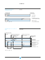
¢âÕ¡Ÿ≈¢Õß Masterpact
NX 08
HA1
0
Uimp
12kV
Ui 1000V
Ue (V)
690
50kA/
1s
50/60Hz
AS
947-2
UNE
IEC
BS CEI
EN 60947-2
VDE
UTE
mast
erpac
t II
E60350A
IN GERIN
MERL
NBMA
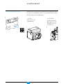
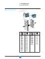
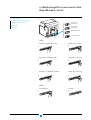
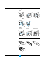
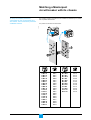
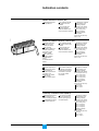
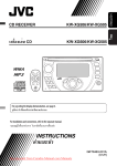
‡∫√§‡°Õ√å¡“ ‡µÕ√å·æ§ NW range ·≈– Swithch-disconnectors ¡’¢π“¥æ‘°¥— °√–· 800 - ∂÷ß 6300 A ·Õ¡ªá·ª√å
·∫àߧÿ≥ ¡∫—µ‘∑’Ë·µ°µà“ß°—π‡ªìπ 5 √–¥—∫
N1: ·∫∫¡“µ√∞“π ·≈– discrimination;
H1: ·∫∫ ¡√√∂¿“æ Ÿß ·≈– discrimination;
H2: ·∫∫ current limiting ·≈– discrimination;
H3: ·∫∫µ—¥µÕπ °√–· Ÿß ·≈– discrimination;
L1: ·∫∫ current limiting Ÿß ·≈– discrimination;
150
Icu kA at
∑’Ë 415 V
Ics = 100% Icu
L1
H3
H2
100
H1
65
42
N1
800 1000 1200 1600 2000 2500 3200 4000 5000 6300
E60036A
E51288A
ªÑ“¬æ‘°—¥
æ‘°—¥°√–· (x 100 A)
√–¥—∫ ¡√√∂π–
≈—°…≥–°“√µ—¥«ß®√
ª√–‡¿∑Õÿª°√≥å: ‡∫√§‡°Õ√åÀ√◊Õ «‘∑´åµ—¥µÕπ
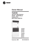
Masterpact
NW08 N1
Ui 1000V
Ue
Uimp 12kV
Icu
(V)
(kA)
220/440
480/690
42
42
Ics = 100% Icu
Icw 42kA/1s cat.B
IEC 60947-2
50/60Hz
UTE VDE BS CEI UNE AS NEMA
3
Masterpact NW08-63
√–¥—∫æ‘°—¥¢Õß©π«π
·√ߥ—π°√–™“°∑’Ë∑π‰¥â
§«“¡ “¡“√∂„π°“√µ—¥µÕπ Ÿß ÿ¥
Ics : ·√ߥ—πæ‘°—¥∑’Ë„™âß“π
Icu : §«“¡ “¡“√∂„π°“√µ—¥µÕπ Ÿß ÿ¥
°√–· æ‘°—¥∑’Ë∑π‰¥â
§«“¡∂’Ë
¡“µ√∞“π
Schneider Electric
¢âÕ¡Ÿ≈¢Õß Masterpact
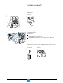
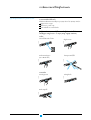
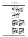
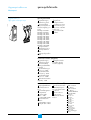
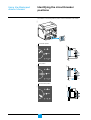
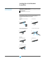
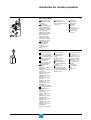
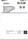
Masterpact ‡∫√§‡°Õ√å¡’∑—Èß√ÿàπ√“߇≈◊ËÕπ·≈–√ÿàπ¬÷¥µ‘¥
√ÿàπ√“߇≈◊ËÕπ®–µ‘¥µ—Èß∫π‚§√ß√“߇≈◊ËÕπ·≈–√ÿàπ¬÷¥µ‘¥ (fixed) ®–µ‘¥µ—Èß∫π·§√à√—∫
E51205C
√ÿàπ√“߇≈◊ËÕπ
E51289C
√ÿàπ¬÷¥µ‘¥
4
Masterpact NW08-63
Schneider Electric
E60037A
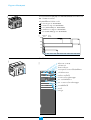
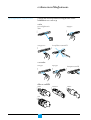
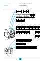
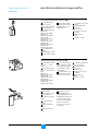
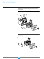
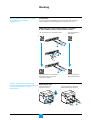
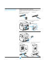
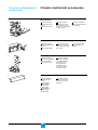
‚§√ß√“߇≈◊ËÕπ
Auxiliary terminal shield
Ω“ªî¥¢—È«µàÕ “¬
Arc-chute cover
·ºàπªî¥™àÕߥ—∫Õ“√å§
Control-unit
contact terminals
Control
auxiliary ON/OFF
terminals indication
contact
Carriage
terminals
switch
terminals
¢—È«µàÕ‡ √‘¡
°“√§«∫§ÿ¡ µ—«™’È√–∫ÿ
ON/OFF
¢—«È µàÕ “¬
«‘∑´å
¢—È«µàÕ “¬§«∫§ÿ¡
Carriage switch terminals
¢—È«µàÕ “¬ «‘∑´å
Carriage switch
terminals
¢—È«µàÕ “¬ «‘∑´å
®ÿ¥ ”À√—∫
ª≈¥Àπâ“
Disconnecting-contact
cluster
§Õπ·∑§
ÀŸÀ‘È«
Carrying grip
Safety shutters
∫“πªî¥‡æ◊ËÕ§«“¡ª≈Õ¥¿—¬
Shutter
locking
blocks
∫“π‡ªî¥
‡æ◊ËÕ°“√≈ÁÕ§
°“√ªÑÕß°—π„ à
Mismatch
‡∫√§‡°Õ√å
º¥‘ √ÿπà
protection
Racking interlock
®ÿ¥ ”À√—∫°“√ Interlock
™àÕ߇°Á∫¥â“¡À¡ÿπ
Drawout grip
Crank storage
ÀŸ ”À√—∫¥÷ßÕÕ°
∫“π‡≈◊ËÕπ∫Õ°µ”ªÀπàߢÕß ∂“π–·≈–°“√≈ÁÕ§
Shutter position indication and locking
Crank
¥â“¡À¡ÿπ
Door interlock
°â“π≈ÁÕ§ª√–µŸ
Locking by keylocks
°“√≈ÁÕ§‚¥¬„™â°ÿ≠·®
"Connected", "test" or "disconnected"
position indicator
ªÿÉ¡· ¥ß ∂“π– "°“√µàÕ", "∑¥ Õ∫" À√◊Õ "ª≈¥ÕÕ°"
Locking by padlocks
°“√≈ÁÕ§‚¥¬„™â°ÿ≠·® “¬¬Ÿ
Position release button
™àÕß„ à¥â“¡À¡ÿπ
Crank socket
ªÿ¡É §≈“¬≈ÁÕ§
5
Masterpact NW08-63
Schneider Electric
¢âÕ¡Ÿ≈¢Õß Masterpact
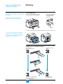
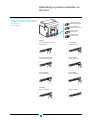
E60038A
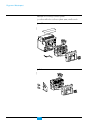
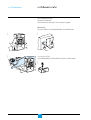
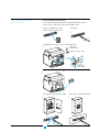
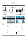
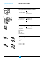
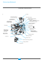
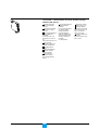
‡∫√§‡°Õ√å / «‘∑´åµ—¥µàÕ
Arc chute
™àÕߥ—∫Õ“√å§
MX/2 opening release or
MN undervoltage release
à«π‡ªî¥«ß®√ MX/2
MN undervoltage
MX/1
π‡ªî¥ release
MX/1 à«opening
®ÿTerminal
¥µàÕ “¬ ”À√—
∫∫Õ° ¿“«–
block
for the ON/OFF
¢ÕߧÕπ·∑§
(ON/OFF)
indication contacts
of 4∫additional
™à2ÕBlocks
ß 2 ™àÕß ”À√—
‡æ‘¡Ë §Õπ·∑§ OF
"ON/OFF" ‡æ‘¡Ë ‰¥â 4 ™ÿ¥
"ON/OFF"
contacts
or EF combined
À√◊
Õ
§Õπ·∑§√à
«
¡
EF
"connected/closed"
"connected/closed" contacts
Terminal block for
the control auxiliaries
®ÿ¥µàÕ “¬§«∫§ÿ¡
Terminal block
for
®ÿ¥µàÕ “¬ ”À√—
∫™ÿ¥§«∫§ÿ¡
the control ·≈–§Õπ·∑§‡ √‘
unit and
¡ SDE
the SDE contact(s)
™àÕß∫Õ° ∂“π––§Õπ·∑§
("ON/OFF" 4 ™ÿ¥)
Block of 4 OF "ON/OFF"
indication contacts
XF ”À√—
closing
release
XF
∫°“√ªî
¥«ß®√√–¬–‰°≈
Àπâ“ —¡º— PF
PF "ready to close"
"ready to close"
contact
Operating-mechanism
¥â“¡™“√å®°≈‰°∑”ß“π
Carrying grip
ÀŸÀ«È‘
charging handle
SDE/2
"fault-trip""fault-trip"
SDE/2
§Õπ·∑§· ¥ß
indication À√◊
contact
Õ√’‡´Á∑√–¬–‰°≈
or Res electrical
MCH ¡Õ‡µÕ√凰’¬√å„™â‰øøÑ“™“√å®
°≈‰°°“√∑”ß“π
MCH gear motor for
electrical charging of
the operating mechanism
remote reset
SDE/1 §Õπ·∑§· ¥ß "fault-trip"
SDE/1 "fault-trip"
indication contact
ªÿÉ¡°¥µàÕ«ß®√
Closing pushbutton
ªÿ¡É °¥‡ªî¥«ß®√
Opening pushbutton
™ÿ¥§«∫§ÿ¡
Control unit
Operation
counter
µ—«π—∫®”π«π§√—
Èß°“√∑”ß“π
ªÿBPFE
É¡°¥ªî¥electrical
¥â«¬‰øøÑ“ BPFE
closing pushbutton
≈ÁÕ§¥â«¬ “¬¬Ÿ
Locking by padlocks
Keylocking kit
™ÿ¥°ÿ≠·®≈ÁÕ§
6
Masterpact NW08-63
Schneider Electric
E60039A
¥â“πÀπâ“
°“√≈ÁÕ§ªÿÉ¡‚¥¬°“√„ à°ÿ≠·®,
°“√ªî¥¥â«Locking
¬´’≈µ–°—Ë«byÀ√◊padlock
Õ≈ÁÕ§¥â«¬
°√Ÿ ”À√—or∫ªÿlead-seal
É¡°¥ cover
for pushbuttons
ET
RES
ªÿÉ¡· ¥ß ¿“«–°“√∑√‘ª„™â
”À√—∫°“√√’‡´Á∑°àÕπªî¥«ß®√
Trip indication button
used to reset before closing
Rating plate
ªÑ“¬æ‘°—¥
IndicatorߢÕ߇¡π§Õπ·∑§
for position
µ—«· ¥ßµ”·Àπà
of the main contacts
7
Masterpact NW08-63
"Springs charged"
and "Ready to close"
indicator
µ—«· ¥ßµ”·Àπàß "Spring charged"
·≈– "Ready to close"
Schneider Electric
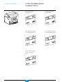
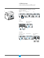
°“√∑”ß“π¢Õß™ÿ¥§«∫§ÿ¡·≈–
°“√· ¥ß°“√∑”ß“π
°“√„™âß“π Masterpact
‡∫√§‡°Õ√åªî¥«ß®√·≈–
ª√‘ß∂Ÿ°¥‘ ™“√å®
E51210A
E51207A
E51320B
‡∫√§‡°Õ√凪߮√·≈–
ª√‘ß∂Ÿ°¥‘ ™“√å®
I
I
ON
Push
ON
Push
O
O
OFF
Push
T
OFF
Push
Test
‡∫√§‡°Õ√åªî¥«ß®√, ª√‘ß∂Ÿ°
™“√å® ·µà¬ß— ‰¡àæ√âÕ¡∑’®Ë –ªî¥«ß®√
E51211
E51206A
‡∫√§‡°Õ√凪߮√, ª√‘ß∂Ÿ°
™“√å® ·µà¬—߉¡àæ√âÕ¡ªî¥«ß®√
I
I
ON
Push
O
ON
Push
O
OFF
Push
OFF
Push
‡∫√§‡°Õ√凪߮√, ª√‘ß
∂Ÿ°™“√å® ·≈–æ√âÕ¡∑’Ë®–
ªî¥«ß®√
E51209A
RESE
I
ON
Push
O
OFF
Push
8
Masterpact NW08-63
Schneider Electric
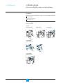
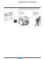
°“√™“√宇∫√§‡°Õ√å
¿“«–°“√™“√客Õß ª√‘ß∂Ÿ°√–∫ÿ¥—ßπ’È
E60370A
™ÿ¥ ª√‘ß„π°≈‰°°“√∑”ß“π¢Õ߇∫√§‡°Õ√å®–µâÕ߉¥â√—∫°“√™“√宇æ◊ËÕ‡°Á∫æ≈—ßß“π∑’Ë„™â
„π°“√ªî¥«ß®√¢ÕßÀπâ“ —¡º— À≈—° ™ÿ¥ ª√‘ßÕ“®®–∂Ÿ°™“√审◊ե⫬¥â“¡‚¬° À√◊Õ‚¥¬
Õ—µ‚π¡—µ‘ ¥â«¬™ÿ¥¡Õ‡µÕ√凰’¬√å (option MCH)
°“√™“√审◊Õ
¥÷ߥⓡ™“√å®≈ß 6 §√—Èß
®π‰¥â¬‘π‡ ’¬ß·§≈Á§
I
ON
Push
O
E51290A
E51213A
OFF
Push
°“√™“√å®Õ—µ‚π¡—µ‘
∂⓵‘¥µ—Èß™ÿ¥¡Õ‡µÕ√凰’¬√å
MCH ™ÿ¥ ª√‘ß®–∂Ÿ°™“√å®
Õ—µ‚π¡—µ‘À≈—ß®“°°“√‡ªî¥
«ß®√„π·µà≈–§√—Èß
or
Test
9
Masterpact NW08-63
Schneider Electric
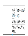
°“√ªî¥«ß®√‡∫√§‡°Õ√å
Õÿª°√≥å "æ√âÕ¡ªî¥«ß®√"
‡ß◊ËÕπ‰¢°“√ªî¥«ß®√
E51291A
°“√„™âß“π Masterpact
°“√ªî¥«ß®√®–∑”‰¥â°ÁµàÕ‡¡◊ËÕ‡∫√§‡°Õ√åÕ¬Ÿà„π ¿“«–æ√âÕ¡ªî¥«ß®√ "ready to close"
‘Ëß®”‡ªìπ≈à«ßÀπâ“¡’¥—ßπ’È
Õÿª°√≥å‡ªî¥ (OFF)
ª√‘߉¥â√—∫°“√™“√å®
‰¡à¡’§” —Ë߇ªî¥¡“√ÕÕ¬Ÿà
∂Ⓡ∫√§‡°Õ√剡à "æ√âÕ¡ªî¥«ß®√" ‡¡◊ËÕ∂Ÿ° —Ëß„Àâ∑”ß“π „ÀâÀ¬ÿ¥·≈– —Ëß„À¡à‡¡◊ËÕ‡∫√§‡°Õ√å
"æ√âÕ¡ªî¥«ß®√"
E51292A
Õÿª°√≥剡à "æ√âÕ¡‡ªî¥«ß®√"
°“√ªî¥«ß®√‡∫√§‡°Õ√å
E51214A
E51216A
∑’˵—«‡∫√§‡°Õ√å (·∫∫·¡§§“π‘§)
°¥ªÿÉ¡ ON
Pus
O
OFF
Push
∑’˵—«‡∫√§‡°Õ√å (·∫∫‰øøÑ“)
XF
E51215A
E51294A
BPFE
°¥ªÿÉ¡ —Ëߪ߮√¥â«¬‰øøÑ“
™ÿ¥‡∫√§‡°Õ√å®–ªî¥«ß®√‚¥¬
„™â‰øøÑ“ (locally) ¥â«¬°“√
‡æ‘Ë¡Õÿª°√≥å XF
Remotely
‡¡◊ËÕµàÕ·ºß§«∫§ÿ¡√–¬–‰°≈ ™ÿ¥ XF (0.85-1.1 Un)
®–„™â„π°“√ªî¥«ß®√√–¬–‰°≈
E51294A
E51293A
XF
®ÿ¥¡ÿàßÀ¡“¬¢Õß°≈‰°¢Õß Anti-pumping
Function ‡æ◊ËÕ∑’Ë„Àâ·πà„®«à“‡¡◊ËÕ‡∫√§‡°Õ√剥â√—∫§” —Ë߇ªî¥·≈–ªî¥«ß®√æ√âÕ¡°—π
®–‰¡à‡ªî¥·≈–ªî¥·∫∫‰¡à·πàπÕπ
„π¢≥–‡ªî¥«ß®√Õ¬Ÿà À“°¡’§” —Ëߪ߮√Õ¬à“ßµàÕ‡π◊ËÕß™ÿ¥‡∫√§‡°Õ√嬗ߧ߇ªî¥«ß®√Õ¬Ÿà
„π¿“«–‡¥‘¡®π°√–∑—Ëߧ” —Ëߪî¥À¬ÿ¥ ·≈–®–µâÕß¡’§” —Ëߪ߮√„À¡à®÷ß®–ªî¥«ß®√
‡∫√§‡°Õ√剥⠷µà∂â“™ÿ¥ªî¥«ß®√µàÕ°—∫™ÿ¥ PF §Õπ·∑§ "ready to close" °Á‰¡à®”‡ªìπ
µâÕß¡’§” —Ëߪ߮√„À¡à
10
Masterpact NW08-63
Schneider Electric
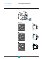
°“√‡ªî¥«ß®√‡∫√§‡°Õ√å
E51217A
E51216A
∑’˵—«‡∫√§‡°Õ√å
°¥ªÿÉ¡ OFF
I
ON
Push
°“√§«∫§ÿ¡®“°√–¬–‰°≈
„™â„π«‘∏’µàÕ‰ªπ’È
à«π‡ªî¥«ß®√ (MX1 and MX2, 0.7 ∂÷ß 1.1 Un);
™ÿ¥ undervoltage MN (0.35 ∂÷ß 0.7 Un);
™ÿ¥ undervoltage MN (0.35 ∂÷ß 0.7 Un) æ√âÕ¡™ÿ¥Àπà«ß‡«≈“ (R À√◊Õ Rr)
‡¡◊ÕË µàÕ‡¢â“°—∫·ºß§«∫§ÿ¡√–¬–‰°≈ “¡“√∂„™â™πÈ‘ à«π‡À≈à“π’„È π°“√‡ªî¥«ß®√‡∫√§‡°Õ√å
√–¬–‰°≈‰¥â
Delay unit
E51296A
MX1, MX2, MN
E51294
E51293A
Push
1
2
3
4 5
6
S
3 6
0.5
30 V
100/1C
AC/D
1
11
Masterpact NW08-63
2
1
1.5
3
MN
r de R
UV
dateu
Retardelay for
Time
MN
UVR
10 12
3
Schneider Electric
°“√„™â Masterpact
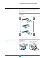
°“√√’‡´Á∑À≈—ß°“√∑√‘ª
‡∫√§‡°Õ√å àß —≠≠“≥∑√‘ª‚¥¬
ªÿÉ¡· ¥ßº≈°“√∑√‘ª¢â“ßÀπâ“
§Õπ·∑§· ¥ßº≈∑√‘ª SDE ™ÿ¥∑’Ë 1 À√◊Õ 2 (SDE/2 ‡ªìπ option)
E51297B
E51216A
∑’˵—«‡∫√§‡°Õ√å
∂Ⓡ∫√§‡°Õ√å‰¡à‰¥âª√–°Õ∫¥â«¬™ÿ¥√’‡´Á∑Õ—µ‚π¡—µ‘¡“¥â«¬ µâÕß√’‡´Á∑¥â«¬¡◊Õ
°“√§«∫§ÿ¡®“°√–¬–‰°≈
„™âÕÿª°√≥å‡ √‘¡‡æ◊ËÕ√’‡´Á∑√–¬–‰°≈¥â«¬‰øøÑ“ Res (‰¡à “¡“√∂„™â°—∫ SDE/2)
E51298B
E51293A
ET
RES
12
Masterpact NW08-63
Schneider Electric
°“√≈ÁÕ§ à«π§«∫§ÿ¡
°“√≈ÁÕ§°“√‡ªî¥/ªî¥«ß®√¢Õ߇∫√§‡°Õ√å∑’˵—«‡∫√§‡°Õ√å
´’≈¥â«¬µ–°—Ë«
E51301B
E51300B
·¡à°ÿ≠·®
°√Ÿ
E51337A
E51283A
°“√≈ÁÕ§ªÿÉ¡°¥‚¥¬„™â·¡à°ÿ≠·® (‡ âπºà“»Ÿπ¬å°≈“ß 5-8 mm),
´’≈¥â«¬µ–°—Ë« À√◊Õ¢—π °√Ÿ
Test
°“√≈ÁÕ§
ªî¥¥â«¬·ºàπªî¥
E51303B
E51302B
„ à°ÿ≠·®, ´’≈¥â«¬µ–°—Ë«
À√◊Õ¢—π¥â«¬ °√Ÿ
O
I
Push OFF
Push ON
°“√§≈“¬≈ÁÕ§
13
Masterpact NW08-63
ªÿÉ¡°¥®–Õ¬Ÿà„π ¿“æ
‰¡à∂°Ÿ ≈ÁÕ§
E51305B
¬°Ω“ªî¥·≈–‡ªî¥≈ß
E51304B
E51303B
∂Õ¥·¡à°ÿ≠·®, ‡Õ“µ–°—Ë«
∑’Ë´’≈ À√◊Õ °√ŸÕÕ°
O
I
Push OFF
Push ON
Schneider Electric
°“√≈ÁÕ§ à«π§«∫§ÿ¡
°“√„™â Masterpact
Àâ“¡°“√ªî¥«ß®√∑’Ë®ÿ¥„™âß“π (local) ·≈–√–¬–‰°≈ (remote)
√–∫∫≈ÁÕ§√«¡
‡æ◊ËÕ‰¡à„Àâªî¥«ß®√‡∫√§‡°Õ√å∑—Èß∑’Ë®ÿ¥„™âß“π (local) ·≈–√–¬–‰°≈ (remote) „Àℙ⫑∏’¥—ßπ’È
≈ÁÕ§¥â«¬·¡à°ÿ≠·®
°ÿ≠·®≈ÁÕ§ 1 À√◊Õ 2 ™ÿ¥
≈ÁÕ§√«¡∑—Èß 2 √–∫∫
°“√·¢«π·¡à°ÿ≠·® 1-3 ™ÿ¥
(√Ÿ·¢«π 5-8 mm)
°“√≈ÁÕ§
·¢«π·¡à°ÿ≠·®
E51307A
I
¥÷ßÀŸ¢â“ßÕÕ°¡“
E51306A
E51217A
‡ª‘¥«ß®√‡∫√§‡°Õ√å
ON
Push
Push
°“√µ√«® Õ∫
E51218A
™ÿ¥ªî¥«ß®√‰¡à∑”ß“π
I
ON
Push
Pus
O
OFF
Push
Push
°“√§≈“¬≈ÁÕ§
E51308A
∂Õ¥·¡à°ÿ≠·®ÕÕ°
14
Masterpact NW08-63
Schneider Electric
°“√≈ÁÕ§™ÿ¥§«∫§ÿ¡¥â«¬°ÿ≠·®≈ÁÕ§ 1 À√◊Õ 2 ™ÿ¥
°“√≈ÁÕ§
∂Õ¥°ÿ≠·®ÕÕ°
E51311A
I
ON
Push
À¡ÿπ°ÿ≠·®
E51310A
E51217A
‡ª‘¥«ß®√‡∫√§‡°Õ√å
Push
°“√µ√«® Õ∫
E51218A
™ÿ¥ªî¥«ß®√‰¡à∑”ß“π
I
ON
Push
Pus
O
OFF
Push
Push
°“√§≈“¬≈ÁÕ§
À¡ÿπ°ÿ≠·®
°ÿ≠·®‰¡à “¡“√∂∂Õ¥ÕÕ°‰¥â
E51319A
E51313A
E51312A
‡ ’¬∫°ÿ≠·®
§’¬å≈ÁÕ§ 4 ·∫∫∑’Ë„™â‰¥â
RONIS
CASTELL
E51271A
E51270A
E51269A
PROFALUX
E51272A
KIRK
15
Masterpact NW08-63
Schneider Electric
°“√√–∫ÿ ∂“π–¢Õ߇∫√§‡°Õ√å
°“√„™âß“π Masterpact
·∫∫‚§√ß√“߇≈◊ËÕπ
E51222A
∑’Ë¥â“πÀπâ“¢Õ߇∫√§‡°Õ√å®–¡’µ—«∫Õ°µ”·Àπàß°“√∑”ß“π¢Õ߇∫√§‡°Õ√å
Test
Test
E51314A
E51219A
µ”·Àπàß "µàÕ"
Test
E51315A
E51220A
µ”·Àπàß "∑¥ Õ∫"
Test
26 mm
E51316A
E51221A
µ”·Àπàß "‰¡àµàÕ"
Test
16
Masterpact NW08-63
Schneider Electric
°“√¥÷߇∫√§‡°Õ√凢â“ÕÕ°®“°‚§√ß√“߇≈◊ËÕπ
‘Ëß®”‡ªìπ∑’˵âÕß∑”°àÕπ°“√¥÷߇∫√§‡°Õ√åÕÕ°®“°‚§√ß√“߇≈◊ËÕπ
°“√¥”‡π‘π°“√π’ȵâÕߪî¥øíß°å™—Ëπ
°“√≈ÁÕ§‚§√ß√“߇≈◊ËÕπ (¥ŸÀπâ“ 21)
‡π◊ËÕß®“°°“√µàÕ·≈–ª≈¥«ß®√ Masterpact µâÕß„™â¥â“¡À¡ÿπ ‡æ◊ËÕ¥÷߇∫√§‡°Õ√åÕÕ°
¥—ßπ—Èπ√–∫∫°“√≈ÁÕ§µà“ßÊ ®–µâÕßÀâ“¡„™âß“π°“√¥÷߇∫√§‡°Õ√åÕÕ°®“°‚§√ß√“߇≈◊ËÕπ
µâÕ߉¡à„™âß“πøíß°å™—Ëπ°“√≈ÁÕ§
°“√ª≈¥‡∫√§‡°Õ√宓°µ”·ÀπàßµàÕ«ß®√‰ª¬—ßµ”·Àπàß∑¥ Õ∫ ·≈–
µ”·Àπà߉¡àµàÕ«ß®√
‡∫√§‡°Õ√åÕ¬Ÿà„πµ”·Àπàß "∑¥ Õ∫"
E51223B
‡∫√§‡°Õ√åÕ¬Ÿà„πµ”·Àπàß "µàÕ"
Test
Test
Test
1
2
Test
4
3
Test
6
Test
Test
5
‡∫√§‡°Õ√åÕ¬Ÿà„πµ”·Àπàß "∑¥ Õ∫" ∂Õ¥¥â“¡À¡ÿπ
ÕÕ°À√◊ÕÀ¡ÿπµ—«‰ªµ”·Àπàß "‰¡àµàÕ"
§”‡µ◊Õπ : √“ߥâ“π¢«“®–‰¡à “¡“√∂∂Õ¥ÕÕ°‰¥â
∂⓬—߉¡à‰¥â∂Õ¥¥â“¡¢—πÕÕ° À√◊Õ‡∫√§‡°Õ√å
‰¡à‰¥â‡ªî¥«ß®√
‡∫√§‡°Õ√åÕ¬Ÿà„π
µ”·Àπàß "‰¡àµàÕ"
°“√∂Õ¥ÕÕ°®“°√“ß
„π°“√„ à°≈—∫ °¥®ÿ¥§≈“¬≈ÁÕ§
·≈⫺≈—°√“ß°≈—∫‡¢â“‰ª
1
E51226B
E51224B
°¥®ÿ¥§≈“¬≈ÁÕ§·≈â«¥÷ßÕÕ°
®“°√à“ß
Test
Test
2
17
Masterpact NW08-63
3
Schneider Electric
°“√„™âß“π Masterpact
·∫∫‚§√ß√“߇≈◊ËÕπ
µ√«® Õ∫µ”·ÀπàߢÕ߇∫√§‡°Õ√å∫π√“ß«à“«“ß
Õ¬Ÿà∫π®ÿ¥√Õß√—∫∑—Èß 4
E51217A
E51227A
°àÕπ∑”°“√µ‘¥µ—È߇∫√§‡°Õ√å µ√«® Õ∫„Àâ¡—Ëπ„®«à“
‡‡∫√§‡°Õ√å “¡“√∂„ à‡¢â“°—∫‚§√ß√à“߉¥â
‡ªî¥«ß®√‡∫√§‡°Õ√å
(„π∑ÿ°°√≥’ √–À«à“ß°“√
µ‘¥µ—È߇∫√§‡°Õ√å®–‡ªî¥«ß®√
‚¥¬Õ—µ‚π¡—µ‘)
°“√„ à Masterpact
‡æ◊ËÕ¢âÕ¡Ÿ≈∑’Ë ¡∫Ÿ√≥å„π°“√„™âß“π·≈–µ‘¥µ—Èß
¥Ÿ„π§Ÿà¡◊Õ°“√µ‘¥µ—Èß
I
ON
Push
Push
Test
E51228B
º≈—°‡∫√§‡°Õ√凢Ⓞπ‚§√ß√“߇≈◊ËÕπ, √–«—ßÕ¬à“„Àâ‚¥π™ÿ¥§«∫§ÿ¡
°“√„ à‡∫√§‡°Õ√宓°µ”·Àπàß "‰¡àµÕà " ‰ª¬—ßµ”·Àπàß "∑¥ Õ∫" ·≈⫉ªµ”·Àπàß "µàÕ"
Õÿª°√≥åÕ¬Ÿàµ”·Àπàß "‰¡àµàÕ"
Õÿª°√≥åÕ¬Ÿàµ”·Àπàß "∑¥ Õ∫"
E51230B
∂Ⓣ¡à “¡“√∂„ à‡∫√§‡°Õ√å≈ß„π‚§√ß√“߇≈◊ËÕπ‰¥â
„Àâµ√«® Õ∫√ÿàπ¢Õ߇∫√§‡°Õ√å·≈–‚§√ß√“߇≈◊ËÕπ
«à“¡’≈—°…≥–µ√ß°—πÀ√◊Õ‰¡à
Test
Test
Test
1
2
Test
4
3
Test
6
Test
Test
5
Õÿª°√≥åÕ¬Ÿà„πµ”·Àπàß "∑¥ Õ∫"
¥÷ߥⓡÀ¡ÿπÕÕ°À√◊ÕÀ¡ÿπµàÕ‰ª¬—ßµ”·Àπàß "µàÕ"
18
Masterpact NW08-63
Õÿª°√≥åÕ¬Ÿà„πµ”·Àπàß "µàÕ"
Schneider Electric
°“√®—∫§Ÿà Masterpact
‡∫√§‡°Õ√å°—∫‚§√ß√à“ß
‡æ◊ËÕªÑÕß°—π°“√®—∫§Ÿàº‘¥¢Õ߇∫√§‡°Õ√å·≈–‚§√ß√—∫
„À⥟§Ÿà¡◊Õ°“√µ‘¥µ—Èß °“√ªÑÕß°—π°“√®—∫§Ÿàº‘¥
°“√ªÑÕß°—π®—∫§Ÿàº‘¥®–∑”„Àâ¡—Ëπ„®‰¥â«à“‡∫√§‡°Õ√å®–µ‘¥µ—Èß∫π‚§√ß√à“ß∑’Ë¡’≈—°…≥–µ√ß°—π
E51317B
“¡“√∂®—∫§Ÿà°—π‰¥âµ“¡µ“√“ß
A
B
D
C
2
E
4
G
6
F
1
3
5
7
ABCD
ABCE
ABCF
ABCG
ABDE
ABDF
ABDG
ABEF
ABEG
ABFG
ACDE
ACDF
ACDG
ACEF
ACEG
ACFG
ADEF
ADEG
ADFG
AEFG
19
Masterpact NW08-63
567
467
457
456
367
357
356
347
346
345
267
257
256
247
246
245
237
236
235
234
BCDE
BCDF
BCDG
BCEF
BCEG
BDEF
BDEG
BDFG
CDEF
CDEG
CEFG
DEFG
167
157
147
146
137
136
135
134
127
126
124
123
Schneider Electric
°“√≈ÁÕ§ª√–µŸ «‘∑´å∫Õ√å¥
°“√„™âß“π Masterpact
·∫∫‚§√ß√“߇≈◊ËÕπ
E51231B
Õÿª°√≥å≈ÕÁ §®–∂Ÿ°µ‘¥µ—ßÈ Õ¬Ÿ¥à “â π´â“¬À√◊Õ¢«“¢Õß‚§√ß√à“ß
‡¡◊ÕË ‡∫√§‡°Õ√åÕ¬Ÿ„à πµ”·Àπàß "µàÕ" À√◊Õµ”·Àπàß "∑¥ Õ∫", ≈—°°≈Õπ®–∂Ÿ°
ª≈àÕ¬≈ß·≈–ª√–µŸ≈ÁÕ§
‡¡◊ÕË ‡∫√§‡°Õ√åÕ¬Ÿ„à πµ”·Àπàß "‰¡àµÕà ", ≈—°°≈Õπ®–∂Ÿ°¬°¢÷Èπ∑”„Àâª√–µŸ§≈“¬≈ÁÕ§
Test
°“√ªÑÕß°—πª√–µŸ‡ªî¥
„ à Masterpact „πµ”·Àπàß
'∑¥ Õ∫" À√◊Õµ”·Àπàß "µàÕ"
Test
ª√–µŸ≈ÁÕ§
E51233A
E51235A
E51232A
ªî¥ª√–µŸ
°“√¬°‡≈‘°°“√ªÑÕß°—πª√–µŸ‡ªî¥
Test
20
Masterpact NW08-63
E51236A
E51234A
„ à Masterpact „πµ”·Àπàß ª√–µŸ®–∂Ÿ°§≈“¬·≈–‡ªî¥‰¥â
"‰¡àµÕà "
Schneider Electric
°“√≈ÁÕ§‡∫√§‡°Õ√å„ÀâÕ¬Ÿà„πµ”·Àπàß
°ÿ≠·® “¬¬Ÿ·≈–§’¬å≈ÁÕ§Õ“®®–∂Ÿ°„™âß“π√à«¡°—π
°“√√«¡√–∫∫≈ÁÕ§‡¢â“¥â«¬°—π
‡æ◊ÕË ªÑÕß°—π°“√ —ßË ‡ªî¥-ªî¥‡∫√§‡°Õ√å∑®Ë’ ¥ÿ §«∫§ÿ¡ (local) À√◊Õ√–¬–‰°≈ (remote) ®–µâÕß„™â :
·¡à°ÿ≠·®®”π«π 1-3 ™ÿ¥
§’¬å≈ÁÕ§®”π«π 1 À√◊Õ 2 ™ÿ¥
√«¡√–∫∫≈ÁÕ§∑—Èß 2 √–∫∫‡¢â“¥â«¬°—π
°“√Àâ“¡°“√µàÕ«ß®√‡∫√§‡°Õ√凡◊ËÕ‡∫√§‡°Õ√åÕ¬Ÿà„πµ”·Àπàß "‰¡àµàÕ"
‚¥¬„™â°ÿ≠·® “¬¬Ÿ®”π«π 1 ∂÷ß 3 ™ÿ¥ ( “¬¬Ÿ ø Ÿß ÿ¥ 5-8 mm.)
¥÷ßÀŸ¢â“ßÕÕ°¡“
E51238A
E51237A
°“√≈ÁÕ§
‡∫√§‡°Õ√å„πµ”·Àπàß "‰¡àµàÕ"
Test
Test
Test
¥â“¡À¡ÿ¥®– Õ¥‰¡à‰¥â
E51240A
E51239A
Õ¥°â“π¢Õß·¡à°ÿ≠·®
(¢π“¥ ø 5-8 mm.)
Test
ª≈àÕ¬ÀŸ¢â“ߧ◊π
E51242A
E51241A
°“√§≈“¬≈ÁÕ§
∂Õ¥·¡à°ÿ≠·®ÕÕ°
Test
Test
E51243B
Õ¥¥â“¡À¡ÿπ‰¥â
Test
OK
21
Masterpact NW08-63
Schneider Electric
°“√≈ÁÕ§‡∫√§‡°Õ√å„ÀâÕ¬Ÿà„πµ”·Àπàß
°“√Àâ“¡°“√µàÕ«ß®√‡∫√§‡°Õ√凡◊ËÕ‡∫√§‡°Õ√åÕ¬Ÿà„πµ”·Àπàß "‰¡àµàÕ"
‚¥¬„™â§’¬å≈ÁÕ§®”π«π 1 À√◊Õ 2 ™ÿ¥
°“√≈ÁÕ§
°ÿ≠·® “¬¬Ÿ·≈–§’¬å≈ÁÕ§Õ“®®–∂Ÿ°„™âß“π√à«¡°—π
‡∫√§‡°Õ√åÕ¬Ÿà„πµ”·Àπàß
"‰¡àµàÕ"
E51237A
E51244A
À¡ÿπ°ÿ≠·®
Test
Test
Test
¥â“¡À¡ÿπ‰¡à “¡“√∂ Õ¥‡¢â“‰¥â
E51240A
E51245A
∂Õ¥°ÿ≠·®ÕÕ°
Test
°“√§≈“¬≈ÁÕ§
À¡ÿπ°ÿ≠·®
Õ¥°ÿ≠·®
E51243B
E51246A
E51247A
¥â“¡À¡ÿπ “¡“√∂ Õ¥‰¥â
Test
Test
Test
OK
§’¬å≈ÁÕ§ 4 ·∫∫∑’Ë„™â‰¥â
E51269A
CASTELL
E51271A
PROFALUX
E51270A
RONIS
E51272A
KIRK
22
Masterpact NW08-63
Schneider Electric
¬°‡≈‘°°“√„™â¥â“¡À¡ÿπ„π∑ÿ°µ”·Àπàß
°“√∑”ß“π„π‚À¡¥π’È ‡∫√§‡°Õ√å®–µâÕß
∂Ÿ°∂Õ¥ÕÕ°®“°‚§√ß√à“ß
E51248A
E51237A
“¡“√∂ª√—∫øíß°å™—Ëπ°“√≈ÁÕ§¥â«¬ “¬¬ŸÀ√◊Õ°ÿ≠·®≈ÁÕ§‰¥â ‰¡à‡æ’¬ß·µà°“√≈ÁÕ§∑’Ë
µ”·Àπàß "‰¡àµàÕ" ‡∑à“π—Èπ ¬—ß “¡“√∂≈ÁÕ§‡∫√§‡°Õ√剥â∑ÿ°µ”·Àπàß
ª√—∫‡∫√§‡°Õ√剪∑’˵”·Àπàß "‰¡àµàÕ"
„ à¥â“¡À¡ÿπ
·≈â«∂Õ¥‡∫√§‡°Õ√åÕÕ°®“°‚§√ß√à“ß
Test
Test
E51318B
Test
À¡ÿπ∑’Ë®—∫‰ª∑“ߴ⓬ ‡∫√§‡°Õ√å®– “¡“√∂≈ÁÕ§‰¥â∑ÿ°µ”·Àπàß
≈ÁAll-position
Õ§∑ÿ°µ”·Àπàß
locking
in
≈ÁLocking
Õ§‡©æ“–µ”·Àπà
ß "‰¡àµàÕ"
"disconnected"
position
Test
view
¥ârear
“πÀ≈—
ß
E51285A
°“√≈ÁÕ§‡∫√§‡°Õ√å„π¢≥–∑’˪√–µŸ∂Ÿ°‡ªî¥
Test
‡¡◊ËÕª√–µŸªî¥ ®– “¡“√∂„ à¥â“¡À¡ÿπ‰¥â
E51251A
E51250A
‡¡◊ËÕª√–µŸ‡ªî¥ ¥â“¡À¡ÿπ®–‰¡à “¡“√∂„ à‰¥â
Test
Test
23
Masterpact NW08-63
Schneider Electric
°“√≈ÁÕ§ ‡´øµ’È ™—∑‡µÕ√å
°“√≈ÁÕ§°ÿ≠·® “¬¬Ÿ ¿“¬„π‚§√ß√à“ß√Õß√—∫
°“√„™âß“π Masterpact
·∫∫√“߇≈◊ËÕπ
°“√„™âµ—«≈ÁÕ§™—∑‡µÕ√å
„ ൗ«≈ÁÕ§∫π√“ß
E51339A
E51338A
∂Õ¥µ—«≈ÁÕ§ÕÕ°®“°∑’ˇ°Á∫
2
1
E51340A
≈ÁÕ§µ—«≈ÁÕ§¥â«¬ “¬¬Ÿ
Ø5 ➞ Ø8
3
≈—°…≥–°“√≈ÁÕ§ 4 ·∫∫
™—∑‡µÕ√å∫π≈ÁÕ§
™—∑‡µÕ√å≈à“߉¡à≈ÁÕ§
™—∑‡µÕ√å∫π‰¡à≈ÁÕ§
™—∑‡µÕ√å≈à“ß≈ÁÕ§
™—∑‡µÕ√å∫π·≈–≈à“ß≈ÁÕ§
E51343A
E51341A
™—∑‡µÕ√å∫π·≈–≈à“߉¡à≈ÁÕ§
24
Masterpact NW08-63
Schneider Electric
´—µ‡µÕ√å
∫πªî¥closed.
Top
shutter
Bottom
´—µ‡µÕ√åshutter
≈à“߇ªî¥ open.
Test
´—µ‡µÕ√å
∫π‡ªîopen.
¥
Top
shutter
Bottom
´—µ‡µÕ√åshutter
≈à“ßªî¥ closed.
Test
Top
and∫bottom
´—µ‡µÕ√å
π·≈–≈à“߇ªî¥
shutters open.
Test
Top and bottom
´—µ‡µÕ√å∫closed.
π·≈–≈à“ߪî¥
shutters
Test
Test
°“√≈ÁÕ§
¥÷ß·∑ª¥â“π´â“¬‡æ◊ËÕ≈ÁÕ§™—∑‡µÕ√å∫π
E51252A
E51254A
„ à “¬¬Ÿ (¢π“¥√Ÿ 5 ∂÷ß 8 ¡¡.)
Test
Test
„ à “¬¬Ÿ (¢π“¥√Ÿ 5 ∂÷ß 8 ¡¡.)
E51255A
E51253A
¥÷ß·∑ª¥â“π¢«“‡æ◊ËÕ≈ÁÕ§™—∑‡µÕ√å≈à“ß
Test
Test
„ à “¬¬Ÿ (¢π“¥√Ÿ 5 ∂÷ß 8 ¡¡.)
E51346A
E51345A
¥÷ß·∑ª∑—Èß 2 ®ÿ¥ ‡æ◊ËÕ≈ÁÕ§∑—Èß 2 ™—∑‡µÕ√å
Test
ª≈¥≈ÁÕ§
‡Õ“ “¬¬Ÿ≈ÁÕ§ÕÕ°
Test
§≈“¬·∑ª
E51257A
E51256A
√–∫∫π’È¡’ 2 øíß°å™—Ëπ :
≈ÁÕ§¥â«¬ “¬Ÿ∑’Ë∫πÀ√◊Õ≈à“ß™—∑‡µÕ√å ;
· ¥ßµ”·ÀπàߢÕß≈–™—∑‡µÕ√å ;
™—∑‡µÕ√å‡ªî¥ ;
™—∑‡µÕ√åªî¥
E60042A
°“√≈ÁÕ§¥â«¬ “¬¬ŸÀ√◊Õ°“√∫Õ°µ”·Àπàß°“√≈ÁÕ§
∑’Ë· ¥ß∑’Ë¥â“πÀπⓇ∫√§‡°Õ√å
Test
25
Masterpact NW08-63
Test
Schneider Electric
°“√°”Àπ¥¢—È«¢Õß°“√µàÕ “¬
°“√°”Àπ¥¢—È«‰øøÑ“
(auxiliaries)
E60352A
º—ß°“√®—¥«“ߢ—È«µàÕ “¬
CD3
834
832
831
CD2
824
822
821
CD1
814
812
811
or
Com UC1 UC2
E5 E6 Z5 M1 M2 M3
E3 E4 Z3 Z4 T3 T4
E1 E2 Z1 Z2 T1 T2
MN/MX2
D2/C12
/C13
D1/C11
OF24
244
242
241
or
MX1
C2
C3
C1
OF23
234
232
231
XF
A2
A3
A1
OF22
224
222
221
CE6 CE5
364 354
362 352
361 351
CE4
344
342
341
UC3 UC4 M2C/M6C
F2 + V3 484/Q3 184/K2
VN V2 474/Q2 182
F1 - V1 471/Q1 181/K1
SDE1
84
82
81
CE3
334
332
331
CE2
324
322
321
CE1
314
312
311
PF MCH
254 B2
252 B3
251 B1
OF21
214
212
211
or
or
or
EF23
238
236
235
EF22
228
226
225
EF21
218
216
215
OF14
144
142
141
OF13
134
132
131
OF12
124
122
121
OF11
114
112
111
or
or
or
or
EF14
148
146
145
EF13
138
136
135
OF4 OF3 OF2 OF1
44
34
24 14
42
32
22 12
41
31
21 11
CT3
934
932
931
CT2
924
922
921
CT1
914
912
911
or
911
912
921
914
922
CT1
931
924
932
CT2
934
CT3
11
2
1
21
14
22
OF1
24
OF2
221
31
32
41
34
42
OF3
111
44
112
OF4
121
114
122
131
OF11
124
132
141
OF12
134
142
OF13
211
144
212
OF14
214
OF21
222
231
224
232
OF22
241
234
242
OF23
244
OF24
B1
B3
B2
MCH
D1/
C11
251
252
A1
254
A3
PF
C1
C13 A2
C3/
XF
C2
MX1
C12
D2/
MN/MX2
331
811
812
821
814
822
CD1
831
824
832
CD2
834
CD3
311
312
321
314
322
CE1
324
CE2
332
334
K181
82
CE3
1
Q181/
K284
2
Q182
SDE1
471/
3
Q184/
474/
V1
484/
V2
F1
M2C/M6C
V3
VN
T2
+
UC4
T1
T4
F2
Z2
T3
UC3
M3
Z1
Z4
M2
E2
Z3
UC2
M1
E1
E4
Z5
E3
UC1
E6
E5
Com
EF24
248
246
245
EF12
128
126
125
EF11
118
116
115
CE9
394
392
391
CE8
384
382
381
CE7
374
372
371
or
CD6
864
862
861
Com
UC1
UC2
E5 E6 Z5 M1 M2 M3
E3 E4 Z3 Z4 T3 T4
E1 E2 Z1 Z2 T1 T2
UC3 UC4 M2C/M6C
484/Q3 184/K2
F2 + V3
V2
VN
474/Q2 182
471/Q1 181/K1
F1 - V1
MN/MX2
D2/C12
/C13
D1/C11
PF
254
252
251
MX1
C2
C3
C1
XF
A2
A3
A1
CD4
844
842
841
SDE1
84
82
81
MCH
B2
B3
B1
OF24 OF23 OF22 OF21 OF14 OF13 OF12 OF11 OF4
244
214
234
144
224
134
124
44
114
242
212
232
142
222
132
122
42
112
241
211
231
141
221
131
121
41
111
26
CD5
854
852
851
Masterpact NW08-63
OF3
OF3
34
32
31
OF2
24
22
21
OF1
14
12
11
Schneider Electric
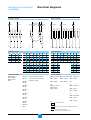
·ºπº—߉øøÑ“
°“√°”Àπ¥¢—È«‰øøÑ“
(auxiliaries)
·∫∫¬÷¥µ‘¥·≈–·∫∫√“߇≈◊ËÕπ
º—ß«ß®√∂Ÿ°· ¥ß¥â«¬«ß®√ de-energised, °“√‡ªî¥«ß®√∑—ÈßÀ¡¥,
°“√µàÕ·≈–°“√™“√å®, ¿“«–ª°µ‘¢Õß√’‡≈¬å
charged
æ√âÕ¡ªî¥
AT
™“√å®
ready to
close
≈—¥«ß®√
fault
Z5
Z4
Z1
cb ª≈“¬∑“ß
Z5
Z4
cb µâπ∑“ß
fault
downstream cb
upstream cb
L3
Z3
L2
Z2
L1
Z1
N
Z3
‰øøÑ
“°”≈—ß
power
°“√§«∫§ÿ¡√–¬–‰°≈
≈—¥«ß®√
™ÿ¥§«∫§ÿ¡
Z2
‰øøÑ“°”≈—ß
BPF
M6C
B2
B3
254
A3
252
A2
C3
C2
C12
D2
84
82
K2
184
182
Q3
Q2
Q1
484
474
Z5
Z4
Z3
Z2
Z1
V3
V2
V1
VN
BPO
MCH
Q
MN
E60067A
E60066A
B1
251
D1
E46136A
E60065A
81
K1
181
E60064A
471
E60063A
H
MCH
F2+
F1
T4
T3
X2
T2
X1
T1
SG2
M3
SG1
M2
M1
E60062A
P
PF
24 V DC
°“√§«∫§ÿ¡√–¬–‰°≈
™ÿ¥§«∫§ÿ¡
A
CH
or
or
E46137A
M6C
or
Com UC1
PF
Res
M2C
XF
MX1
A1
Micrologic
U
MX2
SDE1
C1
SDE2
C11
S1 S2
I
UC2
UC3
UC4 / M2C / M6C
SDE2 / Res
E5 E6 Z5 M1 M2 M3
F2+
V3
/ 484
/ Q3
184
E3 E4 Z3 Z4 T3 T4
VN
V2
/ 474
/ Q2
182
E1 E2 Z1 Z2 T1 T2
F1 –
V1
/ 471
/ Q1
181
/
K2
SDE1
84
MN / MX2
D2
/ C12
82
/
K1
81
D1
/ C11
MX1
XF
C2
A2
254
B2
C3
A3
252
B3
C1
A1
251
B1
™ÿ¥§«∫§ÿ¡
°“√§«∫§ÿ¡√–¬–‰°≈
Com: E1-E6 communication
°“√∫Õ° ∂“π–°“√∑√‘ª¥â«¬°“√≈—¥«ß®√¢ÕߧÕπ·∑§
Res: °“√√’‡´∑√–¬–‰°≈
SDE1: °“√∫Õ° ∂“π–°“√∑√‘ª¥â«¬°“√≈—¥«ß®√ (Õÿª°√≥å¡“µ√∞“π)
MN: °“√ª≈¥ª≈àÕ¬®“°‚«≈∑凵®µË”
À√◊Õ
MX2: °“√ª≈¥ª≈àÕ¬·∫∫¢π“π
MX1: °“√ª≈¥ª≈àÕ¬·∫∫¢π“π (¡“µ√∞“πÀ√◊Õµ‘¥µàÕ)
XF: °“√ª≈¥ª≈àÕ¬ªî¥«ß®√ (¡“µ√∞“πÀ√◊Õµ‘¥µàÕ)
PF: §Õπ·∑§ "æ√âÕ¡ªî¥"
MCH: ‡°’¬√å¡Õ‡µÕ√å (*)
SDE2:
À√◊Õ
;
UC1: Z1-Z5
Z1 = ZSI OUT SOURCE
Z2 = ZSI OUT; Z3 = ZSI IN SOURCE
Z4 = ZSI IN ST (short time)
)
Z5 = ZSI IN GF (
M1 = Vigi module input (Micrologic 7)
°“√Õ‘π‡µÕ√å≈ÁÕ§‚¥¬°“√‡≈◊Õ°‚´π
≈—¥«ß®√≈ߥ‘π
UC2: T1, T2, T3, T4 =
M2, M3 = Vigi module input
(Micrologic 7)
π‘«∑√Õ≈¿“¬πÕ°;
UC3: F2+, F1–
·À≈àß®à“¬‰øøÑ“¿“¬πÕ°
24 V DC
VN ®ÿ¥µàÕ‚«≈∑凵®¿“¬πÕ°
UC4: V1, V2, V3 ®ÿ¥µàÕ‚«≈∑凵®¿“¬πÕ°
(Õÿª°√≥å‡ √‘¡)
À√◊Õ
M2C: 2 §Õπ·∑§‚ª√·°√¡‰¥â (√’‡≈¬å¿“¬„π)
µâÕß°“√·À≈àß®à“¬‰øøÑ“¿“¬πÕ° 24 V DC
À√◊Õ
M6C: 6 §Õπ·∑§‚ª√·°√¡‰¥â (√’‡≈¬å¿“¬„π)
µâÕß°“√·À≈àß®à“¬‰øøÑ“¿“¬πÕ° 24 V DC
‡¡◊ËÕ communicating MX À√◊Õ XF releases ∂Ÿ°„™âß“π “¬‰ø‡ âπ∑’Ë 3
(C3, A3) ®–µâÕß∂Ÿ°µàÕ‰¡à«à“®–µ‘¥µ—Èß‚¡¥Ÿ≈ communication À√◊Õ‰¡à
A : ¥‘®‘µÕ≈·Õ¡ªá¡‘‡µÕ√å
P : A + ¡‘‡µÕ√å«—¥°”≈—߉øøÑ“ + °“√ªÑÕß°—π∑’Ë‚ª√·°√¡‰¥â
H : P + Œ“√å‚¡π‘§
27
Masterpact NW08-63
Schneider Electric
·ºπº—߉øøÑ“
°“√°”Àπ¥¢—È«‰øøÑ“
(auxiliaries)
·∫∫¬÷¥µ‘¥·≈–·∫∫√“߇≈◊ËÕπ
°“√∫Õ° ∂“π–§Õπ·∑§
connected
∑¥ Õ∫
914
912
924
922
314
934
312
test
324
322
332
314
312
µàÕ
324
..8
332
µàÕ
932
connected
334
µàÕ·≈–ªî¥«ß®√
connected
and
closed
322
‰¡àµàÕÀ√◊ÕµàÕ
·≈–‡ªî¥«ß®√
334
not connected
or
connected
and open
..6
..2
12
ªî¥
14
22
24
32
ªî¥
34
42
44
closed
closed
‡ªî¥
..4
open
§Õπ·∑§∑’Ë‚§√ß√à“ß
EF
OF4
OF3
OF2
OF . .
OF1
OF . .
CT3
CE3
CE2
CE1
CE3
CE2
CT2
CT1
CE1
or
911
CT3
931
CE1
921
E60362A
311
331
E60371A
321
°“√∫Õ° ∂“π–§Õπ·∑§
311
321
331
E60361A
..5
..1
E60358A
11
21
31
41
E60357A
CE
§Õπ·∑§∑’Ë‚§√ß√à“ß
OF24 OF23 OF22 OF21 OF14 OF13 OF12 OF11
CD3
CD2
CD1
CE3
CE2
CT2
CT1
OF4
OF3
OF2
OF1
44
34
24
14
244
234
224
214
144
134
124
114
834
824
814
334
324
314
934
924
914
42
32
22
12
242
232
222
212
142
132
122
112
832
822
812
332
322
312
932
922
912
41
31
21
11
241
231
221
211
141
131
121
111
831
821
811
331
321
311
931
921
911
or
or
or
or
or
or
or
or
EF24 EF23 EF22 EF21 EF14 EF13 EF12 EF11
CE6
CE5
or
CE4
CE9
CE8
CE7
248
238
228
218
148
138
128
118
364
354
344
394
384
374
246
236
226
216
146
136
126
116
362
352
342
392
382
372
245
235
225
215
145
135
125
115
361
351
341
391
381
371
°“√∫Õ° ∂“π–§Õπ·∑§
OF4: ‡ªî¥/ªî¥
OF3 · ¥ß ∂“π–
OF2 §Õπ·∑§
OF1
or
OF 24 or
EF 24
· ¥ß ∂“π–§Õπ·∑§‡ªî¥/ªî¥
√à«¡°—∫°“√· ¥ß ∂“π–§Õπ·∑§
"µàÕ/ªî¥"
OF 23 À√◊Õ
EF 23
OF 22 À√◊Õ
EF 22
§Õπ·∑§∑’Ë‚§√ß√à“ß
CD3: ‰¡àµÕà
CD2 µ”·Àπàß
CE3:
CD1
§Õπ·∑§
À√◊Õ
CE6: µàÕ
CE5 µ”·Àπàß
CE4 §Õπ·∑§
CT3:
CE2
µàÕ
µ”·Àπàß
CE1
§Õπ·∑§
CT1
CT2
CE9:
CE8
OF 21 À√◊Õ
EF 21
µ”·Àπàß∑¥ Õ∫
§Õπ·∑§
À√◊Õ
µàÕ
µ”·Àπàß
CE7
§Õπ·∑§
À√◊Õ
CD6: ‰¡àµÕà
CD5 µ”·Àπàß
OF 14 À√◊Õ
EF 14
OF 13 À√◊Õ
EF 13
CD4
§Õπ·∑§
√À— OF12 À√◊Õ
EF12
Õÿª°√≥å·∫∫√“߇≈◊ËÕπ‡∑à“π—Èπ
OF11 À√◊Õ
EF11
XXX
SDE1, OF1, OF2, OF3, OF4 ªìπÕÿª°√≥å¡“µ√∞“π
®ÿ¥µàÕ‡™◊ËÕ¡ (1 “¬µàÕ 1 ®ÿ¥‡∑à“π—Èπ)
*or = À√◊Õ
28
Masterpact NW08-63
Schneider Electric
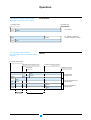
°“√∑”ß“π
ON/OFF ‡ªìπ√À— ∫Õ° ∂“π–¢Õß
Àπâ“ —¡º— À≈—°¢ÕßÕÿª°√≥å
‡∫√§‡°Õ√å
E60363A
completely closed
completely open
‡ªî¥«ß®√ ¡∫Ÿ√≥å
ªî¥«ß®√ ¡∫Ÿ√≥å
open
main contacts
closed
Àπâ“ —¡º— À≈—°
closed
open
closed
open
ON/OFF (‡ªî¥/ªî¥)
°“√√–∫ÿ°“√‡ª≈’ˬπÀπâ“ —¡º— *close = ª‘¥ open = ‡ª‘¥
·∑àπ «‘∑´å®–√–∫ÿ ¿“«– "µàÕ", "∑¥ Õ∫" ·≈–
"‰¡àµàÕ"
E60364A
OF : ON/OFF (closed/open)
indication changeover contacts
‚§√ß√“߇≈◊ËÕπ
completely disconnected
µàÕ ¡∫Ÿ√≥å
separation of the auxiliary circuits
separation of the main circuits
°“√·¬°«ß®√√Õß (auxiliary)
°“√·¬°«ß®√À≈—°
test position
·¬° ¡∫Ÿ√≥å
µ”·Àπàß∑¥ Õ∫
open
closed
open
closed
open
closed
completely connected
CT: test position
carriage switch
·∑àπ «‘∑´å· ¥ß°“√ "∑¥ Õ∫"
closed
open
open
closed
CD: disconnected-position
carriage switch
·∑àπ «‘∑´å· ¥ß°“√ "‰¡àµÕà "
open
closed
closed
open
CE: connected-position
carriage switch
·∑àπ «‘∑´å· ¥ß°“√ "µàÕ"
d> 12.7 mm
d> 25.4 mm
*close = ª‘¥ open = ‡ª‘¥
29
Masterpact NW08-63
Schneider Electric
™ÿ¥§«∫§ÿ¡‰¡‚§√≈Õ®‘§
¢—Õ¡Ÿ≈∑’Ë≈–‡Õ’¬¥°«à“π’È
„À⥟®“°§Ÿà¡◊Õ°“√„™âß“π™ÿ¥§«∫§ÿ¡
™ÿ¥§«∫§ÿ¡‰¡‚§√≈Õ®‘§
E51329A
E46108A
¢âÕ¡Ÿ≈¢ÕßÕÿª°√≥åª√–°Õ∫
Masterpact
‡ªìπÕÿª°√≥å¡“µ√∞“π
¢÷ÈπÕ¬Ÿà°—∫‚¡‡¥≈,
1 ™ÿ¥ ”À√—∫ 10 Õÿª°√≥å
™ÿ¥§«∫§ÿ¡ª√–°Õ∫¥â«¬:
À¡“¬‡≈¢¢Õß™‘πÈ à«π
°“√· ¥ß ∂“π–°“√∑√‘ª
(ª≈—°Í °√–· long-time, ·≈– °“√µ√«®«—¥§à“µà“ßÊ∑“ß
¢—È«µàÕ‰¡à√«¡Õ¬Ÿà¥â«¬) ¥Ÿ®“° ‰øøÑ“ (°√–· , °”≈—߉øøÑ“,
‚«≈∑凵® œ≈œ)
¢â“ß≈à“ß
°“√«‘‡§√“–À匓√å‚¡π‘§
Micrologic 2.0: 33069
Micrologic 5.0: 33070
°“√ ◊ËÕ “√
Micrologic 2.0A: 33071
Micrologic 5.0A: 33072
Micrologic 6.0A: 33073
Micrologic 7.0A: 33074
Micrologic 5.0P: 47058
Micrologic 6.0P: 47059
Micrologic 7.0P: 47060
Micrologic 5.0H: 47061
Micrologic 6.0H: 47062
Micrologic 7.0H: 47063
À¡“¬‡≈¢¢Õß™‘Èπ à«π
”À√—∫¢—È«µàÕ¢Õß A, P, H:
”À√—∫Õÿª°√≥嵑¥µ“¬:
47065
”À√—∫Õÿª°√≥å√ÿàπ√“߇≈◊ËÕπ:
47066.
ª≈—Í°ªÑÕß°—π°√–· ‡°‘π (long-time)
‡ªìπÕÿª°√≥å¡“µ√∞“π
ª≈—Í°‡ªìπµ—«°”Àπ¥™à«ß
1 ™ÿ¥ ”À√—∫ 10 Õÿª°√≥å
°“√ª√—∫µ—Èß°“√ªÑÕß°—π
°√–· ‡°‘π (long-time)
À¡“¬‡≈¢¢Õß™‘πÈ à«π
”À√—∫Õÿª°√≥å‡ √‘¡∑’Ë„™â„π
°“√ª√—∫µ—Èß:
Õÿª°√≥åª√—∫µ—Èß¡“µ√∞“π
0.4 ∂÷ß 1 x Ir : 33542
Õÿª°√≥åª√—∫µ—Èß√–¥—∫µË”
0.4 ∂÷ß 0.8 x Ir : 33543
Õÿª°√≥åª√—∫µ—Èß√–¥—∫ Ÿß
0.8 ∂÷ß 1 x Ir : 33544
‰¡à¡°’ “√ªÑÕß°—π°√–· ‡°‘π
(long-time) : 33545
§Õπ·∑§ M2C ·≈– M6C ( “¡“√∂‚ª√·°√¡‰¥â)
‡ªìπÕÿª°√≥å‡ √‘¡„™â√«à ¡°—∫,
„™â√à«¡°—∫‰¡‚§√≈Õ®‘§ P
·≈– H
À¡“¬‡≈¢™‘πÈ à«π¥Ÿ¢“â ß≈à“ß
(‰¡à√«¡™ÿ¥µàÕ “¬)
2 §Õπ·∑§ M2C:
47086 + 47087
6 §Õπ·∑§ M6C: 47066
À¡“¬‡≈¢™‘Èπ à«π¢Õß
™ÿ¥µàÕ “¬
”À√—∫™ÿ¥µ‘¥µ“¬: 47074
”À√—∫™ÿ¥√“߇≈◊ÕË π : 47849
30
Masterpact NW08-63
“¡“√∂‚ª√·°√¡§Õπ·∑§ M2C: 2 §Õπ·∑§
‚¥¬„™âÀπ⓪í∑¡å∫π™ÿ¥§«∫ (5 A - 240 V)
M6C: 6 §Õπ·∑§
§ÿ¡∑“ßÕÿª°√≥å‡ √‘¡ COM
(5 A - 240 V).
°“√· ¥ßº≈
‚À≈¥∑’ˬա„Àℙ≥â¢Õß
™π‘¥¢Õß°“√≈—¥«ß®√
√’
‡
≈¬å‡Õ“∑åæÿ∑ M6C
°“√≈—¥«ß®√·∫∫
240 V AC:
Instantaneous À√◊Õ¡’°“√ 5 A §à“ p.f = 0.7
380 V AC:
Àπà«ß‡«≈“
3 A §à“ p.f = 0.7
24 V DC:
8A
L/R = 0
48 V DC:
1.5 A
L/R = 0
125 V DC:
L/R = 0
0.4 A
250 V DC:
0.15 A L/R = 0
M6C
:
24 V DC ± 5%
M6C
100 mA
§à“
§à“
§à“
§à“
·À≈àß®à“¬‰ø
°”≈—߉øøÑ“ Ÿß ÿ¥:
Schneider Electric
°“√∫Õ° ∂“π–§Õπ·∑§
°“√∫Õ° ∂“π–§Õπ·∑§ ON/OFF (OF)
‡ªìπÕÿª°√≥å¡“µ√∞“π
4 OF µàÕ 1 Õÿª°√≥å
§Õπ·∑§ OF · ¥ß
∂“π–¢ÕߧÕπ·∑§À≈—°
®–∑√‘ª‡¡◊ËÕ∂÷ß√–¬–ª≈¥
µË” ÿ¥√–À«à“߇¡π§Õπ·∑§
§Õπ·∑§
æ‘°—¥°√–· §«“¡∑πµàÕ°“√≈—¥«ß®√
50/60 Hz ”À√—∫·À≈àß®à“¬‰ø AC
(AC12 µ“¡ 947-5-1):
4 changeover
: 10 A
480 V: 10 A (rms)
600 V: 6 A (rms)
§«“¡∑πµàÕ°“√≈—¥«ß®√
”À√—∫·À≈àß®à“¬‰ø DC
(DC12 µ“¡ 947-5-1):
E51331A
250 V: 3 A.
‡æ‘Ë¡‡µ‘¡°“√∫Õ° ∂“π–§Õπ·∑§ ON/OFF (OFF)
‡ªìπÕÿª°√≥å‡ √‘¡ 2 ™ÿ¥
¢Õß 4 OF §Õπ·∑§µàÕ 1
Õÿª°√≥å
À¡“¬‡≈¢™‘Èπ à«π (‰¡à√«¡
™ÿ¥µàÕ “¬, ¥Ÿ¢â“ß≈à“ß): 1 ™ÿ¥
¢Õß 4 OF §Õπ·∑§ : 47887
À¡“¬‡≈¢™‘Èπ à«π ”À√—∫
™ÿ¥µàÕ “¬ :
”À√—∫Õÿª°√≥å·∫∫µ‘¥µ“¬
: 47074
”À√—∫Õÿª°√≥å√“߇≈◊ËÕπ
: 47849
§Õπ·∑§ OF · ¥ß
∂“π–¢ÕߧÕπ·∑§À≈—°
®–∑√‘ª‡¡◊ËÕ∂÷ß√–¬–ª≈¥
µË” ÿ¥√–À«à“߇¡π§Õπ·∑§
§Õπ·∑§
æ‘°—¥°√–· §«“¡∑πµàÕ°“√≈—¥«ß®√
50/60 Hz ”À√—∫·À≈àß®à“¬‰ø AC
(AC12 µ“¡ 947-5-1):
4 changeover
: 10 A
480 V: 10 A (rms)
600 V: 6 A (rms)
§«“¡∑πµàÕ°“√≈—¥«ß®√
”À√—∫·À≈àß®à“¬‰ø DC
(DC12 as per 947-5-1):
250 V: 3 A.
§Õπ·∑§√à«¡ "µàÕ/ªî¥«ß®√" (EF)
‡ªìπÕÿª°√≥å‡ √‘¡ 8 EF
§Õπ·∑§®–√«¡¢âÕ¡Ÿ≈
§Õπ·∑§µàÕ 1 Õÿª°√≥å
"Õÿª°√≥å∂Ÿ°µàÕ" ·≈–
§Õπ·∑§·µà≈–™ÿ¥®–µ‘¥µ—ßÈ "Õÿª°√≥åªî¥«ß®√" ‡æ◊ËÕ∫Õ°
∑’™Ë ¥ÿ µàÕ¢ÕߧÕπ·∑§‡æ‘¡Ë OF «à“ "ªî¥«ß®√Õ¬Ÿà"
À¡“¬‡≈¢™‘Èπ à«π : 1 EF
§Õπ·∑§ : 48477
§Õπ·∑§
æ‘°—¥°√–· §«“¡∑πµàÕ°“√≈—¥«ß®√
50/60 Hz ”À√—∫·À≈àß®à“¬‰ø AC
(AC12 µ“¡ 947-5-1):
4 changeover
: 10 A
240 V: 10 A (rms)
380 V: 10 A (rms)
480 V: 10 A (rms)
600 V: 6 A (rms)
§«“¡∑πµàÕ°“√≈—¥«ß®√
”À√—∫·À≈àß®à“¬‰ø DC
(DC12 as per 947-5-1):
48 V: 2.5 A
130 V: 0.8 A
250 V: 0.3 A.
°“√∫Õ° ∂“π–§Õπ·∑§ "≈—¥«ß®√-∑√‘ª" (SDE/1)
§Õπ·∑§√–¬–‰°≈· ¥ß
‡ªìπÕÿª°√≥å¡“µ√∞“π
¢Õ߇∫√§‡°Õ√å, 1 SDE/1 °“√‡ªî¥«ß®√¢ÕßÕÿª°√≥å‡π◊ÕË ß
¡“®“°º≈¢Õß°“√≈—¥«ß®√
µàÕ 1 Õÿª°√≥å
‰¡à¡’‡«Õ√å™—Ëπ¢Õß Switchdisconnector
§Õπ·∑§
æ‘°—¥°√–· §«“¡∑πµàÕ°“√≈—¥«ß®√
50/60 Hz ”À√—∫·À≈àß®à“¬‰ø AC
(AC12 µ“¡ 947-5-1):
4 changeover
: 10 A
240 V: 10 A (rms)
380 V: 10 A (rms)
480 V: 10 A (rms)
600 V: 6 A (rms)
§«“¡∑πµàÕ°“√≈—¥«ß®√
”À√—∫·À≈àß®à“¬‰ø DC
(DC12 as per 947-5-1):
48 V: 3 A
125 V: 0.3 A
250 V: 0.15 A.
31
Masterpact NW08-63
Schneider Electric
E51298B
¢âÕ¡Ÿ≈¢ÕßÕÿª°√≥åª√–°Õ∫
Masterpact
°“√∫Õ° ∂“π–§Õπ·∑§
‡æ‘Ë¡‡µ‘¡°“√∫Õ° ∂“π–§Õπ·∑§ "°“√≈—¥«ß®√-∑√‘ª" (SDE/2)
E51298B
‡ªìπÕÿª°√≥å‡ √‘¡ ”À√—∫
§Õπ·∑§√–¬–‰°≈· ¥ß
‡∫√§‡°Õ√å 1 §Õπ·∑§‡æ‘Ë¡ °“√‡ªî¥«ß®√¢ÕßÕÿª°√≥å
SDE/2 µàÕ 1 Õÿª°√≥å
‡π◊ËÕß¡“®“°º≈¢Õß°“√
‰¡à “¡“√∂„™â√à«¡°—∫
≈—¥«ß®√
Õÿª°√≥å‡ √‘¡ Res
À¡“¬‡≈¢™‘πÈ à«π¢Õß:
(‰¡à√«¡™ÿ¥µàÕ “¬¥Ÿ¢“â ß≈à“ß)
1 §Õπ·∑§ SDE/2 :
47915
À¡“¬‡≈¢™‘Èπ à«π¢Õß
™ÿ¥µàÕ “¬
”À√—∫™ÿ¥µ‘¥µ“¬: 47074
”À√—∫™ÿ¥√“߇≈◊ÕË π : 47849
changeover §Õπ·∑§
æ‘°—¥°√–· : 10 A
§«“¡∑πµàÕ°“√≈—¥«ß®√
50/60 Hz ”À√—∫®à“¬‰ø AC
(AC12 µ“¡ 947-5-1):
240 V: 10 A (rms)
380 V: 5 A (rms)
480 V: 5 A (rms)
600 V: 3 A (rms)
§«“¡∑πµàÕ°“√≈—¥«ß®√
”À√—∫®à“¬‰ø DC
(DC12 µ“¡ 947-5-1):
48 V: 3 A
125 V: 0.3 A
250 V: 0.15 A.
Electrical reset after fault trip (Res)
‡ªìπÕÿª°√≥å‡ √‘¡ ”À√—∫
§Õπ·∑§®–√’‡´∑Õÿª°√≥å
1 Res µàÕ 1 Õÿª°√≥å
√–¬–‰°≈ ‡¡◊ËÕ‡°‘¥°“√∑√‘ª
®“°°“√≈—¥«ß®√∑“߉øøÑ“
‰¡à “¡“√∂„™â√à«¡°—∫
Õÿª°√≥å‡ √‘¡ SDE/2
À¡“¬‡≈¢™‘πÈ à«π¢Õß:
(‰¡à√«¡™ÿ¥µàÕ “¬¥Ÿ¢“â ß≈à“ß):
110/130 V AC: 47082
220/240 V AC: 47083
À¡“¬‡≈¢™‘Èπ à«π¢Õß
™ÿ¥µàÕ “¬
”À√—∫™ÿ¥µ‘¥µ“¬: 47074
”À√—∫™ÿ¥√“߇≈◊ÕË π : 47849
"Springs charged" limit switch contact (CH)
Õÿª°√≥åª√–°Õ∫¥â«¬, 1 CH §Õπ·∑§®–· ¥ß ∂“π–
"charged" ¢Õß°≈‰°°“√
§Õπ·∑§µàÕ 1 Õÿª°√≥å
∑”ß“π ( ª√‘ß™“√å®)
changeover §Õπ·∑§
æ‘°—¥°√–· : 10 A
§«“¡∑πµàÕ°“√≈—¥«ß®√
50/60 Hz ”À√—∫®à“¬‰ø AC
(AC12 µ“¡ 947-5-1):
240 V: 10 A (rms)
380 V: 5 A (rms)
480 V: 5 A (rms)
600 V: 3 A (rms)
§«“¡∑πµàÕ°“√≈—¥«ß®√
”À√—∫®à“¬‰ø DC
(DC12 µ“¡ 947-5-1):
E51332A
48 V: 3 A
125 V: 0.3 A
250 V: 0.15 A.
§Õπ·∑§ "æ√âÕ¡‡ªî¥" (PF)
changeover §Õπ·∑§
‡ªìπÕÿª°√≥å 1 §Õπ·∑§
§Õπ·∑§Õ“®®–· ¥ß«à“
æ‘°—¥°√–· : 10 A
PF µàÕ 1 Õÿª°√≥å
Õÿª°√≥凪߮√Õ—π‡π◊ËÕß
§«“¡∑πµàÕ°“√≈—¥«ß®√
¡“®“°
À¡“¬‡≈¢™‘πÈ à«π¢Õß:
50/60 Hz ”À√—∫®à“¬‰ø AC
(AC12 µ“¡ 947-5-1):
(‰¡à√«¡™ÿ¥µàÕ “¬¥Ÿ¢“â ß≈à“ß)
‡∫√§‡°Õ√凪߮√Õ¬Ÿà
240 V: 10 A (rms)
1 §Õπ·∑§ PF :
°≈‰°¢Õß ª√‘ß∂Ÿ°™“√å®
380 V: 5 A (rms)
À¡“¬‡≈¢™‘Èπ à«π¢Õß
‰¡à¡§’ ” —ßË „Àâª¥î «ß®√§â“߉«â §«“¡∑πµàÕ°“√≈—¥«ß®√
™ÿ¥µàÕ “¬
‰¡à¡§’ ” —ßË „À⇪߮√§â“߉«â ”À√—∫®à“¬‰ø DC
(DC12 µ“¡ 947-5-1):
”À√—∫™ÿ¥µ‘¥µ“¬: 47074
48 V: 3 A
”À√—∫™ÿ¥√“߇≈◊ÕË π : 33098
125 V: 0.3 A
250 V: 0.15 A.
32
Masterpact NW08-63
Schneider Electric
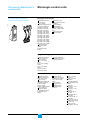
E51290A
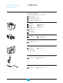
Õÿª°√≥åª√–°Õ∫ ”À√—∫°“√§«∫§ÿ¡√–¬–‰°≈
‡°’¬√å¡Õ‡µÕ√å (MCH)
‡ªìπÕÿª°√≥å‡ √‘¡, ‡°’¬√å
¡Õ‡µÕ√åµàÕ 1 Õÿª°√≥å :
À¡“¬‡≈¢™‘Èπ à«π
(‰¡à√«¡™ÿ¥µàÕ “¬, ¥Ÿ¢â“ß≈à“ß) :
‡°’¬√å¡Õ‡µÕ√å®–™“√å®·≈– ‡«≈“°“√™“√å® :
√’™“√å® ª√‘ß ‚¥¬Õ—µ‚π¡—µ‘ 4 «‘π“∑’ Ÿß ÿ¥
°”≈—߉øøÑ“:
180 VA AC
100/130 V AC: 47893
200/240 V AC: 47894
277 V AC: 47895
380/415 V AC: 47896
400/440 V AC: 47897
480 V AC: 47898
24/30 V DC: 47888
48/60 V DC:47889
100/125 V DC: 47890
200/250 V DC: 47891.
180 W DC
°√–· æÿà߇¢â“ :
2 ∂÷ß 3 In „π 0.1 «‘π“∑’
Õ—µ√“°“√∑”ß“π :
Ÿß ÿ¥ 3 §√—ÈßµàÕπ“∑’
E51294A
À¡“¬‡≈¢™‘Èπ à«π ”À√—∫
™ÿ¥µàÕ “¬ :
”À√—∫Õÿª°√≥嵑¥µ“¬ : 47074
”À√—∫Õÿª°√≥å√“߇≈◊ÕË π : 47849
Õÿª°√≥åª≈¥ª≈àÕ¬°“√‡ªî¥«ß®√ MX/1 ·≈– MX/2, Õÿª°√≥åª≈¥ª≈àÕ¬°“√ªî¥«ß®√ XF
‡ªìπÕÿª°√≥å‡ √‘¡ MX 1
À√◊Õ 1 ™ÿ¥µàÕ 1 Õÿª°√≥å·≈–
MX 1 À√◊Õ™ÿ¥µàÕ 1 Õÿª°√≥å :
°“√∑”ß“π¢Õß MX ·≈–
XF ®–∂Ÿ°°”À𥂥¬µ”·Àπàß∑’˵‘¥µ—Èߧլ≈å
À¡“¬‡≈¢™‘Èπ à«π¢Õß™ÿ¥
µàÕ “¬ :
”À√—∫Õÿª°√≥嵑¥µ“¬ : 47074
”À√—∫Õÿª°√≥å√“߇≈◊ÕË π : 47849
Õÿª°√≥å MX ®– —Ë߇ªî¥
«ß®√¢Õ߇∫√§‡°Õ√å∑—π∑’
À¡“¬‡≈¢™‘Èπ à«π
∑’Ë∂Ÿ°°√–µÿâπ
(‰¡à√«¡™ÿ¥µàÕ “¬, ¥Ÿ¢â“ß≈à“ß) :
Õÿª°√≥å MF ®– —Ëߪ߮√
¢Õ߇∫√§‡°Õ√å∑—π∑’∑’Ë∂Ÿ°
√ÿàπ¡“µ√∞“π
°√–µÿâπ, ∂â“Õÿª°√≥åπ—Èπ
12 V AC
50/60 Hz / DC: 33658
"æ√âÕ¡ªî¥"
‡«≈“µÕ∫ πÕߢÕßÕÿª°√≥å :
MX: 50 ms ± 10
XF: 70 ms +10 / -15
> 3200 A: 80 ms ± 10
operating threshold:
MX: 0.7 to 1.1 x Un
XF: 0.85 to 1.1 x Un
“¡“√∂®à“¬‰øøÑ“‰¥âµàÕ‡π◊ËÕß
°”≈—߉øøÑ“:
pick-up (80 ms):
200 VA
: 4.5 VA.
¢≥–∑”ß“π
24/30 V AC
50/60 Hz / DC: 33659
48/60 V AC
50/60 Hz / DC: 33660
100/130 V AC
50/60 Hz / DC: 33661
200/250 V AC
50/60 Hz / DC: 33662
277 V AC
50/60 Hz / DC: 33663
380/480 V AC
50/60 Hz / DC: 33664
500/550 V AC
50/60 Hz / DC: 33665.
√ÿàπ Communication
(¡’Õÿª°√≥å‡ √‘¡ com) :
12 V AC
50/60 Hz / DC: 33032
24/30 V AC
50/60 Hz / DC: 33033
48/60 V AC
50/60 Hz / DC: 33034
100/130 V AC
50/60 Hz / DC: 33035
200/250 V AC
50/60 Hz / DC: 33036
240/277 V AC
50/60 Hz / DC: 33037
380/480 V AC
50/60 Hz / DC: 33038
33
Masterpact NW08-63
Schneider Electric
E51294A
¢âÕ¡Ÿ≈¢ÕßÕÿª°√≥åª√–°Õ∫
Masterpact
Õÿª°√≥åª√–°Õ∫ ”À√—∫°“√§«∫§ÿ¡√–¬–‰°≈
Õÿª°√≥åª≈¥ª≈àÕ¬∑—π∑’ˇ¡◊ËÕ‚«≈∑凵®µË” (MN)
‡ªìπÕÿª°√≥å‡ √‘¡ MN
Õÿª°√≥åª≈¥ª≈àÕ¬ MN
1 ™ÿ¥µàÕ 1 Õÿª°√≥å
®– —ßË ‡ªî¥«ß®√¢Õ߇∫√§‡°Õ√å
‰¡à “¡“√∂„™â√à«¡°—∫ MX/2 ∑—π∑’∑’Ë‚«≈∑凵®¢Õß√–∫∫
À¡“¬‡≈¢™‘πÈ à«π¢Õß:
‰øøÑ“∑’Ë®à“¬µ°≈ß
(‰¡à√«¡™ÿ¥µàÕ “¬ ¥Ÿ¢“â ß≈à“ß):
24/30 V AC
50/60 Hz / DC: 33668
48/60 V AC
50/60 Hz / DC: 33669
100/130 V AC
50/60 Hz / DC: 33670
200/250 V AC
50/60 Hz / DC: 33671
380/480 V AC
50/60 Hz / DC: 33673
500/550 V AC
50/60 Hz / DC: 33674
‡«≈“µÕ∫ πÕߢÕßÕÿª°√≥å:
90 ms ±5
operating threshold:
:
0.35 to 0.7 x Un
: 0.85 x Un
:
pick-up (80 ms):
200 VA
: 4.5 VA
°“√‡ªî¥«ß®√
°“√ªî¥«ß®√
°”≈—߉øøÑ“
¢≥–∑”ß“π
E51296A
À¡“¬‡≈¢™‘Èπ à«π¢Õß
™ÿ¥µàÕ “¬
”À√—∫™ÿ¥µ‘¥µ“¬: 47074
”À√—∫™ÿ¥√“߇≈◊ÕË π : 47849
1
2
3
4 5
™ÿ¥Àπà«ß‡«≈“ ”À√—∫Õÿª°√≥åª≈¥ª≈àÕ¬ MN
6
S
3 6
0.5
1
2
3
1
1.5
3
MN
r de R
UV
dateu
Retardelay for
Time
MN
UVR
30 V
100/1C
AC/D
10 12
‡ªìπÕÿª°√≥å‡ √‘¡ MN ·≈–
™ÿ¥Àπà«ß‡«≈“ 1 ™ÿ¥µàÕ 1
Õÿª°√≥å
À¡“¬‡≈¢™‘πÈ à«π¢Õß™ÿ¥
Àπà«ß‡«≈“ (µâÕß —Ë߇æ‘Ë¡®“°
MN):
E51333A
48/60 V AC
50/60 Hz / DC: 33680
100/130 V AC
50/60 Hz / DC: 33681
200/250 V AC
50/60 Hz / DC: 33682
380/480 V AC
50/60 Hz / DC: 33683.
°“√∑”ß“π¢Õß™ÿ¥Àπà«ß‡«≈“
¢ÕßÕÿª°√≥åª≈¥ª≈àÕ¬ MN
‡ªìπ°“√ªÑÕß°—π°“√∑√‘ª¢Õß
‡∫√§‡°Õ√å„π™à«ß‡«≈“ —ÈπÊ
¢Õß‚«≈∑凵®µ°
Õÿª°√≥åπ’È®–µàÕ “¬§«∫§ÿ¡
Õπÿ°√¡°—∫ MN ·≈–®–µâÕß
µ‘¥µ—Èß¿“¬πÕ°µ—«‡∫√§‡°Õ√å
‡«≈“µÕ∫ πÕߢÕßÕÿª°√≥å:
«‘π“∑’
0.5, 1, 1.5, 3
operating threshold:
:
0.35 to 0.7 x Un
: 0.85 x Un
°“√‡ªî¥«ß®√
°“√ªî¥«ß®√
°”≈—߉øøÑ“:
pick-up (80 ms):
200 VA
: 4.5 VA
¢≥–∑”ß“π
ªÿÉ¡°¥§«∫§ÿ¡¥â«¬‰øøÑ“ ”À√—∫ªî¥«ß®√ (BPFE)
‡ªìπÕÿª°√≥å‡ √‘¡
BPFE 1 ™ÿ¥µàÕ 1 Õÿª°√≥å
À¡“¬‡≈¢™‘Èπ à«π:
(‰¡à√«¡™ÿ¥µàÕ “¬ ¥Ÿ¢“â ß≈à“ß):
48534
À¡“¬‡≈¢™‘Èπ à«π¢Õß
™ÿ¥µàÕ “¬
”À√—∫Õÿª°√≥嵑¥µ“¬:
47074
”À√—∫Õÿª°√≥å√“߇≈◊ÕË π :
47849
34
Masterpact NW08-63
Õ¬Ÿà∑’Ë®ÿ¥≈ÁÕ§‡∫√§‡°Õ√å
¥â«¬ “¬¬ŸÀ√◊ե⫬°ÿ≠·®,
ªÿÉ¡°¥π’È®– àß —≠≠“≥§«∫§ÿ¡
¥â«¬‰øøÑ“‰ªªî¥«ß®√‡∫√§‡°Õ√å
ºà“π∑“ßÕÿª°√≥åª≈¥ª≈àÕ¬
XF ‚¥¬®–µ√«® Õ∫øíß°å™—Ëπ
¥â“𧫓¡ª≈Õ¥¿—¬µà“ßÊ
∑—Èß∑“ߥâ“π°“√§«∫§ÿ¡·≈–
°“√µ√«® Õ∫
Schneider Electric
E46103A
Õÿª°√≥åª√–°Õ∫¥â“π°≈‰°
µ—«π—∫®”π«π°“√∑”ß“π (CDM)
E46120A
0399
‡ªìπÕÿª°√≥å‡ √‘¡ CDM
1 ™ÿ¥µàÕ 1 Õÿª°√≥å
À¡“¬‡≈¢™‘πÈ à«π: 48535
µ—«π—∫®”π«π°“√∑”ß“π
®–π—∫®”π«π√«¡¢Õß°“√
∑”ß“π
·ºàπªî¥™àÕß«à“ß (CDP)
CDP ®–∑”„Àâ√–∫∫°“√
ªÑÕß°—π IP ‡æ‘Ë¡¢÷Èπ‡ªìπ 40
·≈– IK ‡æ‘Ë¡¢÷Èπ‡ªìπ 07
(Õÿª°√≥å·∫∫µ‘¥µ“¬·≈–
√“߇≈◊ËÕπ)
E46118A
‡ªìπÕÿª°√≥å‡ √‘¡ CDP
1 ™ÿ¥µàÕ 1 Õÿª°√≥å
À¡“¬‡≈¢™‘πÈ à«π:
”À√—∫™ÿ¥µ‘¥µ“¬: 48601
”À√—∫™ÿ¥√“߇≈◊ÕË π : 48603
Ω“§√Õ∫„ à (CCP)
‡ªìπÕÿª°√≥å‡ √‘¡ CCP
1 ™ÿ¥µàÕ 1 Õÿª°√≥å
ª√–°Õ∫¥â«¬ CDP
À¡“¬‡≈¢™‘πÈ à«π: 48604
( ”À√—∫‡∫√§‡°Õ√å·∫∫
µ‘¥µ“¬·≈–·∫∫√“߇≈◊ÕË π)
35
Masterpact NW08-63
‡¡◊ËÕª√–°Õ∫‡¢â“°—∫ CDP
Õÿª°√≥å CCP ®–∑”„Àâ√–¥—∫
°“√ªÑÕß°—π IP ‡æ‘Ë¡‡ªìπ 54
·≈– IK ‡æ‘Ë¡‡ªìπ 10
(Õÿª°√≥å·∫∫µ‘¥µ“¬·≈–
√“߇≈◊ËÕπ)
Schneider Electric
E46238A
¢âÕ¡Ÿ≈¢ÕßÕÿª°√≥åª√–°Õ∫
Masterpact
Õÿª°√≥åª√–°Õ∫¥â“π°≈‰°
Ω“ªî¥·∫∫„ ªÑÕß°—πªÿÉ¡°¥≈ÁÕ§¥â«¬ “¬¬Ÿ, ºπ÷°µ–°—Ë«À√◊Õ °√Ÿ
E46579A
‡ªìπÕÿª°√≥å‡ √‘¡ Ω“ªî¥≈ÁÕ§ Ω“ªî¥·∫∫„ ªÑÕß°—π°“√
°¥ªÿ¡É °¥‡æ◊ÕË °“√‡ªî¥À√◊Õªî¥
1 ™ÿ¥µàÕ 1 Õÿª°√≥å
À¡“¬‡≈¢™‘πÈ à«π: 48536 ‡∫√§‡°Õ√å
µâÕß°“√Õÿª°√≥å≈ÁÕ§ ‡™àπ
“¬¬Ÿ, ºπ÷°µ–°—Ë« À√◊Õ °√Ÿ
Õßµ—«
™ÿ¥≈ÁÕ§‡∫√§‡°Õ√å„ÀâÕ¬Ÿà„πµ”·Àπàß OFF ‚¥¬„™â “¬¬Ÿ
‡ªìπÕÿª°√≥å‡ √‘¡, √–∫∫°“√ Õÿª°√≥åπ’ȪÑÕß°—π°“√ªî¥
≈ÁÕ§ 1 ™ÿ¥µàÕ 1 Õÿª°√≥å
‡∫√§‡°Õ√å∑’˵—«‡∫√§‡°Õ√å
À¡“¬‡≈¢™‘πÈ à«π: 48539 À√◊Õ®“°°“√§«∫§ÿ¡√–¬–‰°≈
“¡“√∂„™â “¬¬Ÿ≈ÁÕ§‰¥â∂÷ß
3 ™ÿ¥
™ÿ¥≈ÁÕ§‡∫√§‡°Õ√å„ÀâÕ¬Ÿà„πµ”·Àπàß OFF ‚¥¬°ÿ≠·®≈ÁÕ§
‡ªìπÕÿª°√≥å‡ √‘¡, ™ÿ¥≈ÁÕ§
1 ™ÿ¥ µàÕ 1 Õÿª°√≥å
À¡“¬‡≈¢™‘πÈ à«π:
(‰¡à√«¡™ÿ¥≈ÁÕ§)
”À√—∫™ÿ¥°ÿ≠·®≈ÁÕ§·∫∫
Profalux À√◊Õ Ronis :
™ÿ¥≈ÁÕ§ªÑÕß°—π°“√ªî¥
‡∫√§‡°Õ√å∑’˵—«‡∫√§‡°Õ√å
À√◊Õ®“°°“√§«∫§ÿ¡√–¬–‰°≈
48541
”À√—∫™ÿ¥°ÿ≠·®≈ÁÕ§·∫∫
Castell : 48543
”À√—∫™ÿ¥°ÿ≠·®≈ÁÕ§·∫∫
Kirk : 48542
E51286A
E51273A
Ronis
°ÿ≠·®≈ÁÕ§„™â ”À√—∫™ÿ¥≈ÁÕ§
°ÿ≠·®≈ÁÕ§ 1 À√◊Õ 2 µ—«
µàÕ 1 ™ÿ¥≈ÁÕ§
À¡“¬‡≈¢™‘πÈ à«π:
Ronis :
°ÿ≠·®≈ÁÕ§ 1 µ—« : 41940
°ÿ≠·®≈ÁÕ§ 2 µ—« : 41950
Profalux :
E51274A
E51287A
Profalux
°ÿ≠·®≈ÁÕ§ 1 µ—« : 42888
°ÿ≠·®≈ÁÕ§ 1 µ—« : 42878
36
Masterpact NW08-63
Schneider Electric
Õÿª°√≥åª√–°Õ∫¢Õß‚§√ß√à“ß
Bottom shutter closed
E51334A
Top shutter closed
∫“πªî¥‡æ◊ËÕ§«“¡ª≈Õ¥¿—¬
‡ªìπÕÿª°√≥å‡ √‘¡
À¡“¬‡≈¢™‘Èπ à«π
(™ÿ¥¢Õß∫“πªî¥ ”À√—∫¥â“π
∫π·≈–¥â“π≈à“ß)
IP20.
E46293A
NW08/NW40:
3 poles: 48587
4 poles: 48589
NW40b/NW63
3 poles: 48588
4 poles: 48590
µ‘¥µ—Èß∫π‚§√ß√à“ß∫“πªî¥
‡æ◊ËÕ§«“¡ª≈Õ¥¿—¬®–
ªÑÕß°—π°“√‡¢â“∂÷ß™ÿ¥§Õπ·∑§ª≈¥«ß®√‚¥¬Õ—µ‚π¡—µ‘
‡¡◊ËÕÕÿª°√≥åÕ¬Ÿà„πµ”·Àπàß
"‰¡àµàÕ" À√◊Õ "∑¥ Õ∫"
µ—«≈ÁÕ§∫“πªî¥
E46946A
‡ªìπÕÿª°√≥å‡ √‘¡ :
µ—«≈ÁÕ§Õ“®≈ÁÕ§¥â«¬ “¬¬Ÿ‡æ◊ËÕ
2 ™ÿ¥ ”À√—∫ NW08 ∂÷ß
ªÑÕß°—π°“√µàÕÕÿª°√≥å
NW40
≈ÁÕ§∫“πªî¥„ÀâÕ¬Ÿà„π
4 ™ÿ¥ ”À√—∫ NW40b ∂÷ß µ”·Àπà
ߪ‘¥
NW63
À¡“¬‡≈¢™‘Èπ à«π (2 ™ÿ¥)
: 48591
°“√· ¥ßµ”·ÀπàߢÕß∫“πªî¥·≈–°“√≈ÁÕ§Ω“Àπâ“
Õÿª°√≥å‡ √‘¡π’ȵ‘¥µ—ÈßÕ¬Ÿà∑’Ë
¥â“πÀπâ“¢Õß‚§√ß√à“ß
∫Õ°„Àâ∑√“∫«à“∫“πªî¥
Õ¬Ÿà„πµ”·Àπàߪî¥
“¡“√∂„™âß“πÕ¬à“ßÕ‘ √–
À√◊Õ„™âß“π√à«¡°—∫ “¬¬Ÿ≈ÁÕ§
¢Õß∫“πªî¥∑—Èß 2 ™ÿ¥
(∫π·≈–≈à“ß)
E46561A
‡ªìπÕÿª°√≥å‡ √‘¡
À¡“¬‡≈¢™‘Èπ à«π :
NW08/NW040:
3 ·≈– 4 ¢—È« : 48592
NW40b/NW63
3 ¢—È« : 48593
4 ¢—È« : 48594
™ÿ¥≈ÁÕ§‡∫√§‡°Õ√å„πµ”·Àπàߪ≈¥«ß®√
E51273A
E51286A
Ronis
‡ªìπÕÿª°√≥å‡ √‘¡ √–∫∫
°“√≈ÁÕ§ 1 ™ÿ¥µàÕ 1 Õÿª°√≥å
À¡“¬‡≈¢™‘Èπ à«π
”À√—∫°ÿ≠·®≈ÁÕ§ Profaux
À√◊Õ Ronis : 48564
”À√—∫°ÿ≠·®≈ÁÕ§ Castell
: 48566
”À√—∫°ÿ≠·®≈ÁÕ§ Kirk
: 48565
µ‘¥µ—Èß∫π‚§√ß√à“ß·≈–
“¡“√∂‡¢â“∂÷߉¥â„π¢≥–
ª√–µŸªî¥ √–∫∫≈ÁÕ§°“√π’È®–
≈ÁÕ§‡∫√§‡°Õ√å„ÀâÕ¬Ÿ„à πµ”·Àπàß
"‰¡àµàÕ" ‚¥¬„™â°ÿ≠·®≈ÁÕ§
1 À√◊Õ 2 ™ÿ¥
°“√≈ÁÕ§„πµ”·Àπàß
" ‰¡àµàÕ" Õ“®ª√—∫„Àâ≈ÁÕ§
‡∫√§‡°Õ√剥â∑—Èß 3 µ”·Àπàß
°ÿ≠·®≈ÁÕ§„™âß“π√à«¡°—∫√–∫∫°“√≈ÁÕ§„πµ”·Àπàß "‰¡àµàÕ"
°ÿ≠·®≈ÁÕ§ 1 À√◊Õ 2 ™ÿ¥µàÕ√–∫∫°“√≈ÁÕ§
À¡“¬‡≈¢™‘Èπ à«π :
Ronis:
1
2
E51274A
E51287A
Profalux
°ÿ≠·®≈ÁÕ§: 41940
°ÿ≠·®≈ÁÕ§: 41950
Profalux:
1
2
°ÿ≠·®≈ÁÕ§: 42888
°ÿ≠·®≈ÁÕ§: 42878
37
Masterpact NW08-63
Schneider Electric
E46652A
Õÿª°√≥åª√–°Õ∫¢Õß‚§√ß√à“ß
°“√≈ÁÕ§ª√–µŸ
E46124A
‡ªìπÕÿª°√≥å‡ √‘¡, ¥â“¡≈ÁÕ§
ª√–µŸ 1 ™ÿ¥µàÕ 1 ‚§√ß≈à“ß
À¡“¬‡≈¢™‘πÈ à«π: 47914
“¡“√∂µ‘¥µ—È߉¥â∑—Èߥâ“π
Õÿª°√≥åπ’ȪÑÕß°—π°“√‡ªî¥
´â“¬·≈–¥â“π¢«“¢Õß
Ω“µŸâ ”À√—∫ «‘∑´å∫Õ√å¥
‡¡◊ËÕ‡∫√§‡°Õ√åÕ¬Ÿà„πµ”·Àπàß ‚§√ß√à“ß
"µàÕ" À√◊Õ "∑¥ Õ∫"
™ÿ¥Ω“≈ÁÕ§Àπâ“
E46111A
‡ªìπÕÿª°√≥å‡ √‘¡, ™ÿ¥Ω“
Õÿª°√≥åπ’ȪÑÕß°—π°“√„ à
≈ÁÕ§Àπâ“ 1 ™ÿ¥µàÕ 1 Õÿª°√≥å ¥â“¡ rack Ω“µŸâ «‘∑´å∫Õ√å¥
À¡“¬‡≈¢™‘πÈ à«π: 48582 ‡ªî¥Õ¬Ÿà
™ÿ¥ªÑÕß°—π°“√„ à‡∫√§‡°Õ√庑¥
‡ªìπÕÿª°√≥å‡ √‘¡, ™ÿ¥
ªÑÕß°—π°“√„ à‡∫√§‡°Õ√庑¥
1 ™ÿ¥µàÕ 1 ‚§√ß√à“ß
À¡“¬‡≈¢™‘πÈ à«π: 33767
E51351A
µ‘¥µ—ÈßÕ¬Ÿà¥â“π¢«“¢Õß
‚§√ß√à“ß
™ÿ¥ªÑÕß°—π°“√„ à‡∫√§‡°Õ√å
º‘¥¡’„Àâ‡≈◊Õ° 20 ·∫∫ ºŸâ„™â
“¡“√∂‡≈◊Õ°„™â„π°“√ªÑÕß°—π
°“√„ à‡∫√§‡°Õ√庑¥µ—«‡¢â“
°—∫‚§√ß√à“ß
Ω“ªî¥¢—È«µàÕ “¬ (CB)
‡ªìπÕÿª°√≥å‡ √‘¡, 1 Ω“ªî¥
1 ™ÿ¥µàÕ 1 ‚§√ß√à“ß
À¡“¬‡≈¢™‘πÈ à«π
NW08/NW040
3 ¢—È«: 48595
4 ¢—È«: 48596
NW40b/NW63
3 ¢—È«: 48597
4 ¢—È«: 48598
38
Masterpact NW08-63
Ω“ªî¥ªÑÕß°—π°“√‡¢â“∂÷ß
®ÿ¥µàÕ “¬§«∫§ÿ¡∑“߉øøÑ“
Schneider Electric
E46095A
«‘∑´å· ßµ”·Àπàß "µàÕ", "‰¡àµàÕ" ·≈– "∑¥ Õ∫"
(carriage switches/CE, CD, CT)
‡ªìπÕÿª°√≥å‡ √‘¡,
1 ∂÷ß 9 «‘∑´å
‚§√ß √â“ß¡“µ√∞“π,
0 ∂÷ß 3 CE, 0 ∂÷ß 3 CD,
0 ∂÷ß 3 CT
√Ÿª·∫∫Õ◊ËπÊ (‚¥¬°“√ —Ëß
Actuator ‡æ‘Ë¡‡µ‘¡) :
0 ∂÷ß 9 CE, 0 CD, 0 CT
0 ∂÷ß 6 CE, 0 ∂÷ß 3 CD,
0 CT
0 ∂÷ß 6 CE, 0 CD, 0 ∂÷ß
3 CT
À¡“¬‡≈¢™‘Èπ à«π
(‰¡à√«¡™ÿ¥µàÕ “¬, ¥Ÿ¢“â ß≈à“ß)
«‘∑´å Carriage 1 ™ÿ¥ :
33170
Actuator 1 ™ÿ¥ ”À√—∫
°“√‡æ‘Ë¡ «‘∑´å Carriage :
48560
À¡“¬‡≈¢™‘Èπ à«π ”À√—∫
™ÿ¥µàÕ “¬ (µàÕ «‘∑´å
Carriage) : 478449
39
Masterpact NW08-63
«‘∑´å Carriage · ¥ß
µ”·Àπàß 3 µ”·Àπàß ¥—ßπ’È :
CE : µ”·Àπàß "µàÕ"
CD : µ”·Àπàß "‰¡àµàÕ"
(‡¡◊ËÕ∂÷ß√–¬–Àà“ßπâÕ¬∑’Ë ÿ¥
¢ÕߧÕπ·∑§À≈—°°—∫
§Õπ·∑§™à«¬)
CT : µ”·Àπàß∑¥ Õ∫
changeover §Õπ·∑§
æ‘°—¥°√–· : 10 A
§«“¡∑πµàÕ°“√≈—¥«ß®√
50/60 Hz ”À√—∫®à“¬‰ø AC
(AC12 µ“¡ 947-5-1):
240 V: 10 A (rms)
380 V: 5 A (rms)
§«“¡∑πµàÕ°“√≈—¥«ß®√
”À√—∫®à“¬‰ø DC
(DC12 µ“¡ 947-5-1):
250 V: 0.3 A.
Schneider Electric
°“√µ√«® Õ∫·≈–°“√∑¥ Õ∫
°àÕπ„™âß“π
°“√∑¥ Õ∫‡√‘Ë¡µâπ
®–µâÕߥ”‡π‘π°“√µ“¡«‘∏’°“√‡À≈à“π’È ‚¥¬‡©æ“–
°àÕπ°“√„™âß“πÕÿª°√≥å Masterpact §√—Èß·√°
°“√µ√«® Õ∫∑—Ë«‰ª¢Õ߇∫√§‡°Õ√å®–„™â‡«≈“ 2-3 «‘π“∑’‡∑à“π—Èπ ·≈–®–∑”„ÀâÀ≈’°‡≈’ˬß
§«“¡‡ ’ˬߵàÕ°“√‡°‘¥§«“¡º‘¥æ≈“¥‰¥â °“√µ√«® Õ∫∑—Ë«‰ªµâÕß∑”¥—ßπ’È
°àÕπ°“√„™âß“π§√—Èß·√°
À≈—ß°“√‰¡à‰¥â„™â‡∫√§‡°Õ√凪ìπ‡«≈“π“π
°“√µ√«®®–µâÕß∑”„π¢≥–∑’˪≈¥‰øøÑ“ÕÕ°®“° «‘∑´å∫Õ√å¥∑—ÈßÀ¡¥ «‘∑´å∫Õ√å¥∑’Ë·∫àß
‡ªìπ à«πÊ ®–µâÕߪ≈¥‰øøÑ“ÕÕ°®“° à«π∑’˺Ÿâµ√«® Õ∫‡¢â“∂÷߉¥â
«‘∏’°“√
°“√∑¥ Õ∫√–∫∫‰øøÑ“
°“√∑¥ Õ∫§«“¡‡ªìπ©π«π·≈– §à“ Dielectric-withstand ®–µâÕß∑”¿“¬À≈—ß√—∫¡Õ∫
µŸâ «‘∑´å∫Õ√å¥ °“√∑¥ Õ∫π’È®–µâÕß∑”Õ¬à“ß·¡à𬔷≈–‡ªìπ‰ªµ“¡¡“µ√∞“π “°≈‚¥¬
ºŸ™â ”π“≠°“√
°àÕπ°“√∑¥ Õ∫®”‡ªìπµâÕß
ª≈¥«ß®√§«∫§ÿ¡∑“߉øøÑ“µà“ßÊ ¢Õ߇∫√§‡°Õ√å (MCH, MX, XF, MN °“√√’‡´∑
√–¬–‰°≈¢Õß Res)
∂Õ¥ª≈—°Í long-time ¢Õß 7.0 A, 5.0 P, 6.0 P, 7.0 P, 5.0 H, 6.0 H, 7.0 H °“√
∂Õ¥ª≈—Í° long-time ®–∑”„Àâ°“√«—¥‚«≈∑凵®¢“‡¢â“∂Ÿ°ª≈¥ÕÕ°¥â«¬
°“√µ√«® Õ∫µŸâ «‘∑´å∫Õ√å¥
°“√µ√«® Õ∫‡∫√§‡°Õ√å«à“µ‘¥µ—Èß„π®ÿ¥∑’Ë –Õ“¥‰¡à¡’‡»…«— ¥ÿµà“ßÊ ·≈–‰¡à¡’Õÿª°√≥å
µ°§â“ßÕ¬Ÿà ‡™à𠇧√◊ËÕß¡◊Õ, ‡»… “¬‰ø, ™‘Èπ à«π‡≈Á°Ê ∑’Ë·µ°À—°, ‡»…‚≈À– œ≈œ
°“√µ√«® Õ∫§«“¡∂Ÿ°µâÕß°—∫‰¥Õ–·°√¡°“√µ‘¥µ—Èß
°“√µ√«®«à“°“√µ‘¥µ—ÈßÕÿª°√≥凪ìπ‰ªµ“¡‰¥Õ–·°√¡:
§à“§«“¡∑π∑“πµàÕ°“√≈—¥«ß®√∑’Ë√–∫ÿ‰«â„πªÑ“¬æ‘°—¥
™π‘¥¢Õß™ÿ¥§«∫§ÿ¡ (™π‘¥, æ‘°—¥)
øíß°å™—Ëπ‡ √‘¡µà“ßÊ ∑’Ë¡’Õ¬Ÿà (°“√§«∫§ÿ¡°“√‡ªî¥-ªî¥√–¬–‰°≈¥â«¬¡Õ‡µÕ√å, Õÿª°√≥å
ª√–°Õ∫µà“ßÊ, ‚¡¥Ÿ≈°“√µ√«®«— ¥ÿ ·≈–°“√· ¥ßº≈µà“ßÊ)
°“√ª√—∫µ—Èß°“√ªÑÕß°—π (°√–· ‡°‘π, °√–· ≈—¥«ß®√, °√–· ≈—¥«ß®√Õ¬à“ß√ÿπ·√ß,
°“√≈—¥«ß®√≈ߥ‘π)
°“√√–∫ÿ°“√ªÑÕß°—π«ß®√ ∫π¥â“πÀπâ“¢Õ߇∫√§‡°Õ√å·µà≈–µ—«
∂“π–¢Õß®ÿ¥µàÕ “¬·≈–Õÿª°√≥åª√–°Õ∫
°“√µ√«® Õ∫°“√µ‘¥µ—ÈßÕÿª°√≥å°—∫ «‘∑´å∫Õ√奷≈–¢—π®ÿ¥µàÕ‰øøÑ“µà“ßÊ „Àâ·πàπ
°“√µ√«® Õ∫°“√µ‘¥µ—ÈßÕÿª°√≥å™à«¬·≈–Õÿª°√≥åª√–°Õ∫µà“ßÊ «à“µ‘¥µ—ÈßÕ¬à“ß∂Ÿ°µâÕß
¢—È«µàÕÕÿª°√≥å‰øøÑ“
¢—È«µàÕ “¬‰ø
¢—È«µàÕ«ß®√‰øøÑ“§«∫§ÿ¡
°“√∑”ß“π
µ√«® Õ∫°“√∑”ß“π¢Õß°≈‰°¢Õ߇∫√§‡°Õ√å
°“√‡ªî¥¢ÕߧÕπ·∑§
°“√ªî¥¢ÕߧÕπ·∑§
°“√µ√«® Õ∫™ÿ¥§«∫§ÿ¡
µ√«® Õ∫™ÿ¥§«∫§ÿ¡·µà≈–™ÿ¥¢Õ߇∫√§‡°Õ√嵓¡§Ÿà¡◊Õ°“√„™âß“π¢Õß™ÿ¥§«∫§ÿ¡
40
Masterpact NW08-63
Schneider Electric
∑”Õ¬à“߉√‡¡◊ËÕ‡∫√§‡°Õ√å∑√‘ª
∫—π∑÷°°“√≈—¥«ß®√
°“√≈—¥«ß®√®–∂Ÿ°·®â߉ª¬—ßÕÿª°√≥å·®âß·≈–§Õπ·∑§™à«¬∑—Èß∑’ˇ∫√§‡°Õ√å·≈–Õÿª°√≥å
§«∫§ÿ¡√–¬–‰°≈ (¢÷ÈπÕ¬Ÿà°—∫«‘∏’°“√µàÕ “¬) ¥Ÿ®“°Àπâ“ 12 ¢ÕߧŸà¡◊Õπ’È·≈–®“°§Ÿà¡◊Õ¢Õß
™ÿ¥§«∫§ÿ¡ ”À√—∫¢âÕ¡Ÿ≈¢Õß°“√· ¥ßº≈°“√≈—¥«ß®√
°“√∫Õ° “‡Àµÿ°“√∑√‘ª
®–‰¡à¡’°“√ªî¥«ß®√°≈—∫ (‚¥¬°“√§«∫§ÿ¡∑’ˇ∫√§‡°Õ√åÀ√◊Õ°“√§«∫§ÿ¡√–¬–‰°≈) °àÕπ
∑’Ë®–∑√“∫·≈–·°â‰¢ “‡Àµÿ¢Õß°“√≈—¥«ß®√·≈â«
°“√≈—¥«ß®√Õ“®¡’ “‡Àµÿ¡“®“°
¢÷πÈ Õ¬Ÿ°à ∫— ™π‘¥¢Õß™ÿ¥§«∫§ÿ¡ ¡’Õªÿ °√≥嫇‘ §√“–Àå°“√≈—¥«ß®√„Àâ‡≈Õ°„™â ¥Ÿ√“¬≈–‡Õ’¬¥
®“°§Ÿà¡◊Õ°“√„™âß“π¢Õß™ÿ¥§«∫§ÿ¡
¢÷ÈπÕ¬Ÿà°—∫™π‘¥¢Õß°“√≈—¥«ß®√·≈–§«“¡ ”§—≠¢Õß‚À≈¥ ®–µâÕß∑”°“√µ√«®«—¥§à“
∑’Ë ”§—≠‚¥¬‡©æ“– ‡™àπ §à“§«“¡‡ªìπ©π«π·≈–§à“ dielectric ¢ÕßÕÿª°√≥å∑’˵‘¥µ—Èß
∑—ÈßÀ¡¥À≈“¬§√—Èß ´÷Ëß®–µâÕß„™âºŸâ‡™’ˬ«™“≠„π°“√∑¥ Õ∫¥â«¬
°“√µ√«® Õ∫‡∫√§‡°Õ√奡◊ËÕ‡°‘¥°“√≈—¥«ß®√
µ√«® Õ∫µ—«¥—∫Õ“√å§ (¥ŸÀπâ“ 43)
µ√«® Õ∫§Õπ·∑§ (¥ŸÀπâ“ 43)
µ√«® Õ∫§«“¡·πàπ¢Õß®ÿ¥µà“ßÊ (¥Ÿ§Ÿà¡◊Õ°“√µ‘¥µ—ÈßÕÿª°√≥å)
µ√«® Õ∫™ÿ¥§Õπ·∑§ª≈¥«ß®√ (¥ŸÀπâ“ 43)
°“√√’‡´∑‡∫√§‡°Õ√å
“¡“√∂√’‡´∑‡∫√§‡°Õ√剥â∑—Èß∑’˵—«‡∫√§‡°Õ√å·≈–∑’Ë®ÿ¥§«∫§ÿ¡√–¬–‰°≈
¥Ÿ¢âÕ¡Ÿ≈«‘∏’°“√√’‡´∑‡∫√§‡°Õ√宓°Àπâ“ 12 „π§Ÿà¡◊Õπ’È
41
Masterpact NW08-63
Schneider Electric
°“√∑”„Àâ‡∫√§‡°Õ√å∑”ß“π
Õ¬à“ß¡’ª√– ‘∑∏‘¿“æ
¢âÕ·π–π”„π°“√∫”√ÿß√—°…“
‚ª√·°√¡∑’Ë·π–π” ”À√—∫Õÿª°√≥å∑’Ë„™â„π ¿“«–
Õÿ≥À¿Ÿ¡‘·«¥≈âÕ¡ : -5 CÌ /+70 CÌ ∫√√¬“°“»ª°µ‘
°“√µ√«® Õ∫µ“¡™à«ß‡«≈“∑’Ë®”‡ªìπ
™à«ß‡«≈“
°“√µ√«® Õ∫
∑ÿ°ªï
‡ªî¥·≈–ªî¥Õÿª°√≥å∑’˵—«Õÿª°√≥å
·≈–∑’Ë®ÿ¥§«∫§ÿ¡√–¬–‰°≈·≈–
‚¥¬°“√§«∫§ÿ¡Õ◊ËπÊ ∑’ˇªìπ
Õÿª°√≥åª√–°Õ∫
∑¥ Õ∫≈”¥—∫¢—ÈπµÕπ°“√∑”ß“π
∑¥ Õ∫™ÿ¥§«∫§ÿ¡‚¥¬„™â
™ÿ¥∑¥ Õ∫¢π“¥‡≈Á°
µ√«® Õ∫µ—«¥—∫Õ“√å§
µ√«® Õ∫§Õπ·∑§À≈—°
µ√«® Õ∫§«“¡·πàπ¢Õß®ÿ¥µàÕµà“ßÊ
µ√«® Õ∫™ÿ¥§Õπ·∑§ª≈¥«ß®√
∑ÿ° 2 ªï À√◊Õ‡¡◊ËÕµ—«∫Õ°
°“√∫”√ÿß√—°…“¢Õß™ÿ¥
§«∫§ÿ¡¢÷Èπ∂÷ß 100
«‘∏°’ “√
¥ŸÀπâ“ 10 ·≈– 11
¥ŸÀπâ“ 10 ·≈– 11
¥Ÿ§¡àŸ Õ◊ °“√„™âß“π¢Õß™ÿ¥§«∫§ÿ¡
¥ŸÀπâ“ 43
¥ŸÀπâ“ 43
¥Ÿ§¡àŸ Õ◊ °“√„™âß“π¢Õß™ÿ¥§«∫§ÿ¡
¥ŸÀπâ“ 44
™‘Èπ à«π∑’˵âÕ߇ª≈’Ë¬πµ“¡®”π«π§√—Èß°“√„™âß“π
™‘Èπ à«π¥—ßπ’ȵâÕ߇ª≈’Ë¬πµ“¡√–¬–‡«≈“ ‡æ◊ËÕ¬◊¥Õ“¬ÿ°“√„™âß“π¢ÕßÕÿª°√≥å
™‘Èπ à«π
ºŸâ∑”
§”Õ∏‘∫“¬ À√◊Õ
«‘∏°’ “√
µ—«¥—∫Õ“√å§
§Õπ·∑§À≈—°
ºŸâ„™â
¥ŸÀπâ“ 43
ºŸâµ√«® Õ∫ : ºŸâ„™â
¥ŸÀπâ“ 43
°“√‡ª≈’ˬπ : ‚¥¬ºà“π∫√‘°“√
À≈—ß°“√¢“¬¢Õß™‰π‡¥Õ√å
MCH ‡°’¬√å¡Õ‡µÕ√å
ºŸâ„™â
¥ŸÀπâ“ 9
°“√Õ‘π‡µÕ√å≈ÁÕ§∑“ß°≈‰° ºŸâ„™â
connecting-rod
ΩÉ“¬∫√‘°“√À≈—ß°“√¢“¬
springs
¢Õß™‰π‡¥Õ√å
MX/MN/XF
ºŸâ„™â
¥ŸÀπâ“ 10 ·≈– 11
°“√‡ª≈’ˬπ™‘Èπ à«πµà“ßÊ ®–µâÕß∂Ÿ°°”À𥮓°¢âÕ¡Ÿ≈¢â“ß≈à“ß √“¬°“√¢ÕßÕ“¬ÿ°“√„™âß“π¢Õß
™‘Èπ à«πµà“ßÊ „π®”π«π¢Õß O/C cycles ∑’Ë°√–æ‘°—¥
®”π«π¢Õß O/C cycle ∑’Ë°√–· æ‘°—¥
™π‘¥¢Õß
‡∫√§‡°Õ√å
Õ“¬ÿ°“√„™â
ß“π Ÿß ÿ¥
Õ“¬ÿ°“√„™âß“π¢Õß™‘Èπ à«πµà“ßÊ
∂÷ß
25000
10000
10000
Connecting-rod
springs,
MCH
12500
∂÷ß
25000
3000
10000
12500
12500
∂÷ß
20000
12500
20000
10000
12500
20000
3000
440 V: 8000
690 V: 6000
440 V: 8000
690 V: 6000
10000
10000
∂÷ß
440 V: 8000
690 V: 6000
2000
10000
12500
∂÷ß
20000
12500
20000
10000
12500
10000
1500
440 V: 5000
690 V: 2500
440 V: 5000
690 V: 2500
3000
10000
∂÷ß
440 V: 5000
690 V: 2500
1250
5000
12500
NW08
NW16
N1/H1/H2
NW08
NW16
L1
NW25
NW20
H1/H2
NW25
NW20
H3
NW20
L1
NW40
NW32
H1/H2
NW32
NW40
H3
NW63
NW40b
H1/H2
µ—«¥—∫Õ“√å§
§Õπ·∑§À≈—°
MX/XF
releases
12500
™π‘¥
™π‘¥
™π‘¥
™π‘¥
™π‘¥
™π‘¥
™π‘¥
∂÷ß
™π‘¥
42
Masterpact NW08-63
Schneider Electric
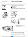
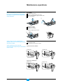
«‘∏’°“√∫”√ÿß√—°…“
°àÕπ∑”°“√∫”√ÿß√—°…“„Àâª≈¥‰øøÑ“
ÕÕ°®“°Õÿª°√≥å·≈–¥”‡π‘π°“√µ“¡§”‡µ◊Õπ
·≈–¡“µ√∞“𧫓¡ª≈Õ¥¿—¬µà“ßÊ
µ—«¥—∫Õ“√å§
E51275A
E51280A
‰¢ °√ŸÕÕ° :
™π‘¥ N1, H1 ·≈– H2 ≤ NW 40: 2 °√Ÿ
™π‘¥ H1 and H2 ≥ NW 40b, type H3: 3 °√Ÿ
™π‘¥ L1: 4 °√Ÿ
µ√«® Õ∫µ—«¥—∫Õ“√å§ :
™àÕß¿“¬„π‰¡à∂Ÿ°°√–∑∫°√–‡∑◊Õπ
separators ‰¡à‡ ◊ËÕ¡
∂â“™ÿ¥§«∫§ÿ¡¡’µ—«√–∫ÿ∫”√ÿß√—°…“
°Á‰¡à®”‡ªìπ„π°“µ√«® Õ∫§Õπ·∑§
E51279A
E51281A
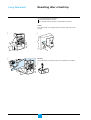
∂â“®”‡ªìπ‡ª≈’Ë¬πµ—«¥—∫Õ“√å§
°“√ ÷°°√àÕπ¢ÕߧÕπ·∑§À≈—°
∂Õ¥µ—«¥—∫Õ“√å§ÕÕ°
ªî¥Õÿª°√≥å·≈–µ√«® Õ∫§Õπ·∑§
∂ⓧÕπ·∑§ ÷°°√àÕπ ®–∑”°“√‡ª≈’ˬπ
‚¥¬»Ÿπ¬å∫√‘°“√¢Õß™‰π‡¥Õ√å
™π‘¥ H1, H2, H3 ( 4000b A)
§Õπ·∑§ ÷°
E51277B
E51276B
§Õπ·∑§ OK
™π‘¥ H1, H2 ( 4000b A), L1
§Õπ·∑§ ÷°
E51282B
E51278B
§Õπ·∑§ OK
43
Masterpact NW08-63
Schneider Electric
«‘∏’°“√∫”√ÿß√—°…“
°“√∑”„Àâ‡∫√§‡°Õ√å∑”ß“π
Õ¬à“ß¡’ª√– ‘∑∏‘¿“æ
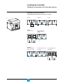
™ÿ¥§Õπ·∑§ª≈¥«ß®√
∑“®“√∫’∑’˧Õπ·∑§‚¥¬„™â®“√∫’µ“¡√“¬°“√„πÀπâ“ 44 ®—¥À“‚¥¬ ∫√‘…—∑ ™‰π‡¥Õ√å
µ√«® Õ∫§Õπ·∑§µ“¡√“¬°“√π’È
‡ªî¥‡∫√§‡°Õ√å
ª≈¥‰øøÑ“ÕÕ°®“°∫— ∫“√å
ª≈¥«ß®√‡∫√§‡°Õ√å
∂Õ¥‡∫√§‡°Õ√å
µ√«® Õ∫§Õπ·∑§ (‰¡à§«√¡Õ߇ÀÁπ∑Õß·¥ß) ‡ª≈’ˬπ™ÿ¥§Õπ·∑§∑’Ë ÷°
µ”·ÀπàߢÕß clusters ‡ªìπ¥—ßµ“√“ߢâ“ß≈à“ßπ’È
E60360A
*pole = ¢—È«
Rating
Type
N1
NW08
H1
NW10
NW12
NW16
NW20
NW25
layout n° 1
2 clusters / pole
layout n° 2
4 clusters / pole
layout n° 3
8 clusters / pole
layout n° 3
8 clusters / pole
layout n° 5
14 clusters / pole
NW32
NW40
NW40b
NW50
NW63
layout n° 4
layout n° 5
layout n° 4
12 clusters / pole 14 clusters / pole 24 clusters / pole
H2
H3
C1
A1
B1
C1
A1
D1
C1
B1
layout n° 5
layout n° 4
E51326A
E51325A
D1
layout n° 3
A1
D1
B1
E1
C1
A1
G1
C2
A2
D2
B2
C2
A2
D2
C2
B2
A2
B1
H1
E1
C1
A1
G1
F1
D1
B1
H1
D2
B2
E2
C2
A2
G2
44
F1
D1
E51328B
layout n° 2
E51324A
layout n° 1
E51327A
L1
Masterpact NW08-63
F2
D2
B2
H2
E2
C2
A2
G2
F2
D2
B2
H2
Schneider Electric
°“√∑”„Àâ‡∫√§‡°Õ√å∑”ß“π
Õ¬à“ß¡’ª√– ‘∑∏‘¿“æ
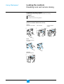
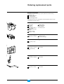
°“√ —Ëß´◊ÈÕÕ–‰À≈à
Õÿª°√≥åª√–°Õ∫∑“߉øøÑ“
E51335A
Õÿª°√≥åª√–°Õ∫∑“߉øøÑ“∑’ËÕ“®®–µâÕ߇ª≈’Ë¬π¡’¥—ßπ’È:
MCH ‡°’¬√å¡Õ‡µÕ√å
Õÿª°√≥åª≈¥ª≈àÕ¬‡ªî¥«ß®√ MX
Õÿª°√≥åª≈¥ª≈àÕ¬ªî¥«ß®√ XF
Õÿª°√≥åª≈¥ª≈àÕ¬‡¡◊ËÕ‚«≈∑凵®µ° MN
µ—«¥—∫Õ“√å§
E46237A
À¡“¬‡≈¢™‘Èπ à«π
NW08 ∂÷ß NW40:
(µ—«¥—∫Õ“√å§ 1 ™ÿ¥) :
1 ™ÿ¥µàÕ¢—È«
NW type N1
NW40b ∂÷ß NW63:
NW08 ∂÷ß NW40 ™π‘¥ H1 2 ™ÿ¥µàÕ¢—È«
·≈– H2: 47935
NW40b ∂÷ß NW63 ™π‘¥
H1 ·≈– H2
NW ™π‘¥ H3: 47936
NW ™π‘¥ L1: 47937
™ÿ¥§Õπ·∑§ª≈¥«ß®√
À¡“¬‡≈¢™‘Èπ à«π (1 ™ÿ¥) ®”π«πµàÕ‡∫√§‡°Õ√å
: 33166
„À⥟®“°Àπ⓵“√“ßÀπâ“ 44
®“√∫’ ”À√—∫™ÿ¥§Õπ·∑§ª≈¥«ß®√
E46109A
À¡“¬‡≈¢™‘Èπ à«π (1 °√–ªÜÕß)
: 33160
¥â“πÀπâ“
E46126A
À¡“¬‡≈¢™‘Èπ à«π
(1 Ω“ ”À√—∫‡∫√§‡°Õ√å
3 À√◊Õ 4 ¢â“ß) : 47939
¥â“¡™“√å®
À¡“¬‡≈¢™‘πÈ à«π (1 ¥â“¡)
: 47940
E51336A
1 Õ—πµàÕ 1 Õÿª°√≥å
1 Õ—πµàÕ 1 Õÿª°√≥å
¥â“¡À¡ÿπ
À¡“¬‡≈¢™‘πÈ à«π (1 ¥â“¡)
: 47944
45
Masterpact NW08-63
1 Õ—πµàÕ 1 Õÿª°√≥å
Schneider Electric
°“√∑”„Àâ‡∫√§‡°Õ√å∑”ß“π
Õ¬à“ß¡’ª√– ‘∑∏‘¿“æ
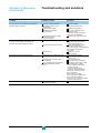
ªí≠À“·≈–·π«∑“ß°“√·°â‰¢
ªí≠À“
“‡Àµÿ∑’ˉª‰¥â
‡∫√§‡°Õ√凪߮√‚¥¬∑’˪ÿÉ¡°¥· ¥ß°“√∑√‘ª‰¡à∑”ß“π
‚«≈∑凵®∑’®Ë “à ¬„ÀâÕªÿ °√≥åª≈¥ª≈àÕ¬‚«≈∑凵®
µ° MN µË”‡°‘π‰ªÀ√◊Õ‰ø¥—∫ ‰ø°√–æ√‘∫
Õÿª°√≥åª≈¥ª≈àÕ¬ MN ∑”ß“πº‘¥ª°µ‘
¡’§” —Ëß„Àâ≈¥‚À≈¥¡“®“°Õÿª°√≥åÕ◊Ëπ
¡’‚«≈∑凵®°√–™“°∑’Ë®ÿ¥µàÕ “¬¢ÕßÕÿª°√≥å
ª≈¥ª≈àÕ¬·∫∫¢π“π MX
¡’°“√‡ªî¥«ß®√∑—π∑’∑’Ë欓¬“¡ªî¥«ß®√‡∫√§‡°Õ√å
(· ¥ßº≈‚¥¬ªÿÉ¡°¥· ¥ß°“√∑√‘ª)
·π«∑“ß°“√·°â‰¢
µ√«® Õ∫‚«≈∑凵®·≈–·°â‰¢ªí≠À“
‡ª≈’ˬπÕÿª°√≥å∑’˺‘¥ª°µ‘
µ√«® Õ∫√–∫∫‰øøÑ“∑—ÈßÀ¡¥·≈–·°â‰¢
°“√ª√—∫µ—ÈߢÕ߇∫√§‡°Õ√å∂â“®”‡ªìπ
µ√«® Õ∫ “‡Àµÿ¢Õߧ” —Ëßπ—Èπ
ªî¥«ß®√¢≥–«ß®√¬—ß≈—¥Õ¬Ÿà
·°â‰¢°“√≈—¥«ß®√ µ√«® Õ∫ ¿“æ
‡∫√§‡°Õ√å°àÕππ”„™âß“πµàÕ
°√–· ‡°‘π™—Ë«¢≥–‡¡◊Ëժ߮√
·°â‰¢√–∫∫‰øøÑ“À√◊Õª√—∫µ—Èß™ÿ¥§«∫§ÿ¡
µ√«® Õ∫ ¿“æ‡∫√§‡°Õ√å°àÕππ”„™âß“πµàÕ
Thermal memory
‰¡à “¡“√∂‡ªî¥«ß®√‡∫√§‡°Õ√宓°°“√§«∫§ÿ¡√–¬–‰°≈
·µà “¡“√∂‡ªî¥«ß®√‰¥â∑’˵—«‡∫√§‡°Õ√å
‚«≈∑凵®∑’Ë®à“¬„ÀâÕÿª°√≥åª≈¥ª≈àÕ¬·∫∫
¢π“π MX ‰¡à‡æ’¬ßæÕ (U < 0.7 Un)
¡’§«“¡º‘¥ª°µ‘¢Õß«ß®√‰øøÑ“¢ÕßÕÿª°√≥å
ª≈¥ª≈àÕ¬·∫∫¢π“π MX
‚«≈∑凵®µ°∑’Ë¢—È«µàÕ “¬¢ÕßÕÿª°√≥å
ª≈¥ª≈àÕ¬ MN µË”°«à“ 0.35 Un
‰¡à “¡“√∂‡ªî¥«ß®√‡∫√§‡°Õ√å∑’˵—«‡∫√§‡°Õ√å
°≈‰≈∑”ß“πº‘¥ª°µ‘ À√◊Õ§Õπ·∑§
À≈Õ¡µ‘¥°—π
46
Masterpact NW08-63
¥Ÿ§Ÿà¡◊Õ°“√„™âß“π™ÿ¥§«∫§ÿ¡
µ√«® Õ∫‚«≈∑凵®∑’Ë®à“¬
∑”„Àâ‚«≈∑凵®Õ¬Ÿà„π™à«ß 0.7 ∂÷ß 1.1 Un
∂Õ¥Ω“Àπâ“ÕÕ°
µ√«® Õ∫Õÿª°√≥åª≈¥ª≈àÕ¬·∫∫¢π“π MX
ª≈¥‚«≈∑凵®∑’Ë®à“¬„ÀâÕÿª°√≥åª≈¥ª≈àÕ¬
MN ¡“‡æ◊ËÕµ√«® Õ∫
‡∫√§‡°Õ√姫√®–‡ªî¥«ß®√
- ∂Ⓣ¡à‡ªî¥«ß®√ „À⇪≈’ˬπ™ÿ¥ª≈¥ª≈àÕ¬
MN
- ∂Ⓡªî¥«ß®√ ®à“¬‰øøÑ“„Àâ°—∫™ÿ¥ª≈¥ª≈àÕ¬
MN Õ’°§√—Èß ·≈– —Ëߪ∫√§‡°Õ√å§àÕ¬Ê
≈¥‚«≈∑凵®≈ß·≈–µ√«® Õ∫«à“Õÿª°√≥å
ª≈¥ª≈àÕ¬ —Ëß„Àâ‡∫√§‡°Õ√凪߮√√–À«à“ß
0.35 ∂÷ß 0.7 Un ∂â“¡’ªí≠À“„À⇪≈’ˬπ
Õÿª°√≥åª≈¥ª≈àÕ¬ MN
µ‘¥µàÕ»Ÿπ¬å∫√‘°“√™‰π‡¥Õ√å
Schneider Electric
°“√∑”„Àâ‡∫√§‡°Õ√å∑”ß“π
Õ¬à“ß¡’ª√– ‘∑∏‘¿“æ
ªí≠À“·≈–·π«∑“ß°“√·°â‰¢
ªí≠À“
“‡Àµÿ∑’ˉª‰¥â
‡∫√§‡°Õ√å‰¡à “¡“√∂ªî¥«ß®√‰¥â¥â«¬°“√§«∫§ÿ¡
∑’ˇ∫√§‡°Õ√åÀ√◊Õ∑’Ë√–¬–‰°≈
ªî¥«ß®√¢≥–¬—ß≈—¥«ß®√
ªÿÉ¡°¥· ¥ß°“√∑√‘ª‰¡à∂Ÿ°√’‡´∑
(°√≥’∑’ˉ¡à¡’°“√√’‡´∑Õ—µ‚π¡—µ‘)
‡∫√§‡°Õ√å "µàÕ" ‰¡à ¡∫Ÿ√≥å
‡°‘¥°“√ Anti-pumpling
‰¡à‰¥â™“√å® ª√‘ߢÕ߇∫√§‡°Õ√å
Õÿª°√≥åª≈¥ª≈àÕ¬ —Ëߪ߮√ XF
¡’‰ø®à“¬Õ¬Ÿàµ≈Õ¥‡«≈“
Õÿª°√≥åª≈¥ª≈àÕ¬·∫∫¢π“π MX
¡’‰øøÑ“®à“¬Õ¬Ÿà
Õÿª°√≥åª≈¥ª≈àÕ¬ MN ‰¡à¡’‰øøÑ“®à“¬
À√◊Õ∑”ß“πº‘¥ª°µ‘
‡∫√§‡°Õ√å∂Ÿ°≈ÁÕ§„πµ”·Àπàß "‡ªî¥«ß®√"
¡’°“√ Interlock ‡∫√§‡°Õ√å
‰¡à “¡“√∂ªî¥«ß®√‡∫√§‡°Õ√宓°°“√§«∫§ÿ¡√–¬–‰°≈
·µàªî¥«ß®√‰¥â∑’˵—«‡∫√§‡°Õ√å
‰¡à “¡“√∂√’™“√宇∫√§‡°Õ√å¥â«¬‰øøÑ“
Õÿª°√≥åª≈¥ª≈àÕ¬ —Ëߪ߮√ XF ¡’‰øøÑ“
®à“¬‰¡à‡æ’¬ßæÕ À√◊Õ∑”ß“πº‘¥ª°µ‘
‰øøÑ“∑’Ë®à“¬„Àâ MCH ‡°’¬√å¡Õ‡µÕ√剡à‡æ’¬ßæÕ
‰¡à “¡“√∂„ à¥â“¡À¡ÿπ‡æ◊ËÕµàÕÀ√◊Õ‰¡àµàÕ«ß®√¢Õ߇∫√§‡°Õ√å
√–∫∫∂Ÿ°≈ÁÕ§„πµ”·Àπàß "µàÕ" À√◊Õ
"‰¡àµàÕ" À√◊Õ¡’°“√ Interlock ∑’Ë Rack
„ à√“߇≈◊ËÕπ‰¡à ÿ¥
¬—߉¡à‰¥â‡Õ“¥â“¡À¡ÿπÕÕ°®“°‡∫√§‡°Õ√å
¬—߉¡àª≈¥«ß®√‡∫√§‡°Õ√å
√–∫∫∂Ÿ°≈ÁÕ§„πµ”·Àπàß "µàÕ" À√◊Õ
"‰¡àµàÕ" À√◊Õ¡’°“√ Interlock ∑’Ë Rack
„ à‡∫√§‡°Õ√庑¥µ—«
‰¡à “¡“√∂∂Õ¥‡∫√§‡°Õ√åÀ√◊Õ‡≈◊ËÕπ√“ߥâ“π¢«“¢Õß‚§√ß√à“ß
‰¡à “¡“√∂„ à‡∫√§‡°Õ√剥â ÿ¥
™ÿ¥§Õπ·∑§ª≈¥«ß®√Õ¬Ÿ„à πµ”·Àπà߉¡à∂°Ÿ µâÕß
∫“πªî¥‡æ◊ËÕ§«“¡ª≈Õ¥¿—¬∂Ÿ°≈ÁÕ§
(≈ÁÕ§¿“¬„π‚§√ß√à“ßÀ√◊Õ¥â“πÀπâ“)
47
Masterpact NW08-63
·π«∑“ß°“√·°â‰¢
°“√·°â‰¢°“√≈—¥«ß®√ µ√«® Õ∫ ¿“æ
‡∫√§‡°Õ√å°àÕπ„™âß“πµàÕ
√’‡´∑ªÿÉ¡°¥
„ à‡∫√§‡°Õ√å°≈—∫„Àâ·πàπ
ª≈¥ª≈àÕ¬‰øøÑ“∑’®Ë “à ¬„ÀâÕªÿ °√≥åª≈¥ª≈àÕ¬
XF ÕÕ°·≈â«®à“¬‰ø„À¡à
µ√«® Õ∫‰øøÑ“∑’®Ë “à ¬„Àâ MCH ‡°’¬√å¡Õ‡µÕ√å
µ√«® Õ∫«ß®√‰øøÑ“
µ√«® Õ∫°“√™“√å® ª√‘ߥ⫬¡◊Õ«à“∑”‰¥â
∂â“®”‡ªìπ„À⇪≈’ˬπ MCH ‡°’¬√å¡Õ‡µÕ√å
ª≈¥·À≈àß®à“¬‰ø¢Õß XF ·≈– àß —≠≠“≥
„Àâªî¥«ß®√„À¡àºà“π∑“ß XF ∂Ⓡ∫√§‡°Õ√å
Õ¬Ÿà„π ∂“π– "æ√âÕ¡ªî¥" ‡∑à“π—Èπ
æ‘®“√≥“«à“∑”‰¡Õÿª°√≥åª≈¥ª≈àÕ¬ MX
®÷ß¡’‰ø®à“¬, µ—¥‰øøÑ“∑’Ë®à“¬„Àâ MX ÕÕ°
·≈â«æ¬“¬“¡ªî¥«ß®√ºà“π∑“ß XF
®à“¬‰øøÑ“ MN ¥â«¬‚«≈∑凵®¡“°°«à“ 0.85 Un
·≈â«æ¬“¬“¡ªî¥«ß®√ºà“π∑“ß XF ∂Ⓡ∫√§‡°Õ√å
‰¡àªî¥«ß®√ ∂Õ¥Ω“Àπâ“ÕÕ°·≈⫵√«® Õ∫
§à“‚«≈∑凵® Pick-up ¢Õß MN «à“∂Ÿ°µâÕßÀ√◊Õ
‰¡à∂“â ‰¡à∂°Ÿ µâÕß„À⇪≈’¬Ë πÕÿª°√≥åª√–°Õ∫
¬°‡≈‘°§” —Ëß≈ÁÕ§
µ√«® Õ∫ “‡Àµÿ ª°µ‘·≈â«®–µâÕ߉¡à¡’°“√
Interlock
µ√«® Õ∫‰øøÑ“∑’Ë®à“¬ (‚«≈∑凵®§«√Õ¬Ÿà
„π™à«ß 0.85 ∂÷ß 1.1 Un)
µ√«® Õ∫‰øøÑ“∑’Ë®à“¬
µ√«® Õ∫‰øøÑ“¢Õß MCH ‡°’¬√å¡Õ‡µÕ√å
欓¬“¡√’™“√å® ª√‘ߥ⫬¡◊Õ
∂â“¡’ªí≠À“∑’Ë°≈‰°°“√∑”ß“πµ‘¥µàÕ»Ÿπ¬å
™‰π‡¥Õ√å
∂â“ “¡“√∂™“√å® ª√‘ߥ⫬¡◊Õ‰¥â · ¥ß«à“
MCH ‡°’¬√å¡Õ‡µÕ√塪’ ≠í À“®”‡ªìπµâÕߪ≈’¬Ë π
ª≈¥≈ÁÕ§ÕÕ° À√◊Õ¬°‡≈‘°§” —Ëß≈ÁÕ§
„ à√“߇≈◊ËÕπ„Àâ ÿ¥
‡Õ“¥â“¡À¡ÿπÕÕ°¡“‡°Á∫„π™àÕ߇°Á∫
ª≈¥«ß®√‡∫√§‡°Õ√å„Àâ‡√’¬∫√âÕ¬
ª≈¥≈ÁÕ§ À√◊Õ¬°‡≈‘°§” —Ëß≈ÁÕ§
µ√«® Õ∫§«“¡∂Ÿ°µâÕߢÕ߇∫√§‡°Õ√å
∂â“∂Ÿ°µâÕß·≈â« „Àâµ√«® Õ∫Õÿª°√≥åªÑÕß°—π
°“√®—∫§Ÿà‡∫√§‡°Õ√å°—∫‚§√ß√à“ߺ‘¥
µ√«® Õ∫µ”·ÀπàߢÕß™ÿ¥§Õπ·∑§ª≈¥«ß®√
ª≈¥≈ÁÕ§
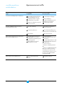
Schneider Electric
E51260B
°“√µ√«® Õ∫ ¿“«–°“√∑”ß“π
¢Õß Masterpact
Õÿ≥À¿Ÿ¡‘·«¥≈âÕ¡
‡∫√§‡°Õ√å Masterpact NW “¡“√∂„™âß“π¿“¬„µâ ¿“«–Õÿ≥À¿Ÿ¡‘¥—ßπ’È :
§à“µà“ßÊ ∑“߉øøÑ“·≈–∑“ß°≈‰° ®–‡ªìπ‰ªµ“¡∑’Ë°”Àπ¥‡¡◊ËÕÕÿ≥À¿Ÿ¡‘·«¥≈âÕ¡
-5 ÌC ∂÷ß +7 ÌC
°“√∑√‘ª¢Õ߇∫√§‡°Õ√å∑”ß“πª°µ‘∑’ËÕÿ≥À¿Ÿ¡‘µË”≈ß∂÷ß -35 ÌC
Masterpact NW (‰¡à¡’™ÿ¥§«∫§ÿ¡) “¡“√∂‡°Á∫√—°…“„π™à«ß¢ÕßÕÿ≥À¿Ÿ¡‘
-40 ÌC ∂÷ß +85 ÌC
™ÿ¥§«∫§ÿ¡ “¡“√∂‡°Á∫√—°…“„π™à«ß¢ÕßÕÿ≥À¿Ÿ¡‘ -25 ÌC ∂÷ß +85 ÌC
E51261B
Test
¢Õ∫‡¢µ¢Õß ¿“«–∫√√¬“°“» Ÿß ÿ¥
‡∫√§‡°Õ√å Masterpact NW ‰¥âºà“π°“√∑¥ Õ∫µ“¡¡“µ√∞“π
‚¥¬°”Àπ¥§à“¢Õ∫‡¢µ ¿“«–∫√√¬“°“»
Ÿß ÿ¥∑’Ë„™âß“π‰¥â¥—ßπ’È
IEC 68-2-1 : Õ“°“»·Àâß, ‡¬Áπ ∑’Ë -55 ÌC
IEC 68-2-2 : Õ“°“»·Àâß, √âÕπ ∑’Ë +85 ÌC
IEC 68-2-30 : Õ“°“»™◊Èπ, √âÕπ (∑’ËÕÿ≥À¿Ÿ¡‘ +55 ÌC, §«“¡™◊Èπ —¡æ—∑∏å 95%)
IEC 68-2-52 : √–¥—∫ 2 : ≈–ÕÕ߇°≈◊Õ
‡∫√§‡°Õ√å Masterpact NW “¡“√∂„™âß“π„π ¿“æ·«¥≈âÕ¡¢ÕßÕÿµ “À°√√¡
∑’Ë°”À𥂥¬¡“µ√∞“π IEC 947 (√–¥—∫¡≈æ‘… 4)
·π–π”„Àâµ√«® Õ∫«à“‡∫√§‡°Õ√剥â∂Ÿ°µ‘¥µ—Èß„πµ”·Àπàß∑’Ë¡’§«“¡‡¬Áπ∑’ˇÀ¡“– ¡
·≈–‰¡à¡’ΩÿÉπ≈–ÕÕß¡“°‡°‘π‰ª
Test
E51262B
§«“¡ —Ëπ –‡∑◊Õπ
‡∫√§‡°Õ√å Masterpact NW ∑π∑“πµàÕ§≈◊Ëπ·¡à‡À≈Á°‰øøÑ“À√◊Õ°“√ —Ëπ –‡∑◊Õπ
°“√∑¥ Õ∫‡ªìπ‰ªµ“¡¡“µ√∞“π IEC 68-2-6 ”À√—∫√–¥—∫∑’˵âÕß°“√¢ÕßÕߧ尓√
µ√«® Õ∫°“√§â“∑“߇√◊Õ (Veritas, Lloyd's, etc.) :
2 to 13.2 Hz: amplitude ±1 mm
13.2 to 100 Hz: constant acceleration 0.7 g.
§«“¡ —Ëπ –‡∑◊Õπ¡“°‡°‘π‰ªÕ“®∑”„À⇰‘¥°“√∑√‘ª, ®ÿ¥µàÕµà“ßÊ ·µ°À—° À√◊Õ§«“¡‡ ’¬À“¬
„π°≈‰°∑“ß°≈µà“ßÊ
Test
48
Masterpact NW08-63
Schneider Electric
E51263B
√–¥—∫§«“¡ Ÿß
2000 m
Masterpact NW ∂Ÿ°ÕÕ°·∫∫„Àâ„™âß“π∑’Ë√–¥—∫§«“¡ ŸßµË”°«à“ 2000 ‡¡µ√ ∑’Ë√–¥—∫
§«“¡ Ÿß¡“°°«à“ 2000 ‡¡µ√ °“√ª√—∫ª√ÿß ¿“æÕ“°“»·«¥≈âÕ¡ (§«“¡µâ“π∑“π
‰øøÑ“, §«“¡ “¡“√∂„π°“√√–∫“¬§«“¡√âÕπ) „ÀâµË”≈ß
§«“¡ Ÿß (¡.)
2000
3000
4000
5000
§à“·√ߥ—π Dielectric withstand
3500
3150
2500
2100
√–¥—∫§«“¡‡ªìπ©π«π‡©≈’ˬ
1000
900
700
600
‚«≈∑凵®„™âß“π Ÿß ÿ¥
690
590
520
460
°√–· æ‘°—¥‡©≈’ˬ∑’Ë 40 ÌC
1 x In
0.99 x In
0.96 x In
0.94 x In
E51264B
Test
°“√√∫°«π¢Õߧ≈◊Ëπ·¡à‡À≈Á°‰øøÑ“
‡∫√§‡°Õ√å Masterpact NW “¡“√∂∑π∑“πµàÕ
·√ߥ—π‡°‘π∑’Ë¡’ “‡Àµÿ®“°Õÿª°√≥å∑’Ë √â“ߧ≈◊Ëπ·¡à‡À≈Á°‰øøÑ“√∫°«π
·√ߥ—π‡°‘π∑’Ë¡’ “‡Àµÿ¡“®“°°“√√∫°«π„π∫√√¬“°“» À√◊Õ®“°√–∫∫®à“¬‰øøÑ“¿“¬πÕ°
‡™àπ (°“√∫°æ√àÕߢÕß√–∫∫‰øøÑ“· ß «à“ß)
Õÿª°√≥å∑’ˇª≈àߧ≈◊Ëπ«‘∑¬ÿ («‘∑¬ÿ, «‘∑¬ÿ ◊ËÕ “√, ‡√¥“√å)
°“√ª≈àÕ¬‰øøÑ“ ∂‘µ¬åµà“ßÊ ®“°ºŸâ„™âß“π
Test
‡∫√§‡°Õ√å Masterpact NW ‰¥âºà“π°“√∑¥ Õ∫‡√◊ËÕߧ≈◊Ëπ·¡à‡À≈Á°‰øøÑ“ (EMC) ∑’Ë
°”À𥂥¬¡“µ√∞“π “°≈
IEC 947-2, ¿“§ºπ«° F
IEC 947-2, ¿“§ºπ«° B (™ÿ¥∑√‘ª¥â«¬øíß°å™—Ëπ°“√√—Ë«≈ߥ‘π)
°“√∑¥ Õ∫¢â“ß∫π¬◊π¬—π«à“
®–‰¡à‡°‘¥°“√√∫°«π°“√∑√‘ª
‡«≈“°“√∑√‘ª®–∂Ÿ°µâÕß
49
Masterpact NW08-63
Schneider Electric
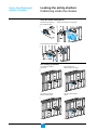
User manual for circuit breakers
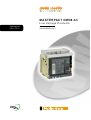
Masterpact NW08-63
Discovering Masterpact
3
Using Masterpact
8
Understanding the controls and indications
8
Charging the circuit breaker
9
Closing the circuit breaker
10
Opening the circuit breaker
11
Resetting after a fault trip
12
Locking the controls
13
Using the Masterpact drawout chassis
16
Identifying the circuit breaker positions
16
Racking
17
Matching a Masterpact circuit breaker with its chassis
19
Locking the switchboard door
20
Locking the circuit breaker in position
21
Locking the safety shutters
24
Identifying the electrical auxiliaries
26
Identification of the connection terminals
26
Electrical diagrams
27
Operation
29
Discovering Masterpact's accessories
30
Micrologic control units
30
Indication contacts
31
Auxiliaries for remote operation
33
Device mechanical accessories
34
Chassis mechanical accessories
36
Inspecting and testing before use
40
Initial test
40
What to do when the circuit breaker trips
41
Maintaining Masterpact performance
42
Recommended maintenance program
42
Maintenance operations
43
Ordering replacement parts
45
Troubleshooting and solutions
46
Checking Masterpact operating conditions
48
2
Masterpact
Schneider Electric
Discovering Masterpact
E46004A
The Masterpact NW range of circuit breakers and switch-disconnectors
offer current ratings from 800 A to 6300 A.
Five different performance levels are available:
N1: standard with total discrimination;
H1: high performance with total discrimination;
H2: a compromise between current limiting and discrimination;
H3: high breaking capacity and discrimination, without current limiting;
L1: high level of current limiting, with some discrimination.
NX 08
HA1
0
Uimp
12kV
Ui 1000V
Ue (V)
690
50kA/
1s
50/60Hz
AS
947-2
UNE
IEC
BS CEI
EN 60947-2
VDE
UTE
mast
erpac
NBMA
t II
E60350A
IN GERIN
MERL
150
Icu kA at 415 V
Ics = 100% Icu
L1
H3
H2
100
H1
65
42
N1
Rating plate
E60036A
E51288A
800 1000 1200 1600 2000 2500 3200 4000 5000 6300
Rated current x 100 A
Performance level
Suitability for isolation
Type of device:
circuit breaker or switch-disconnector
Masterpact
NW08 N1
Ui 1000V
Ue
Rated insulation level
Uimp 12kV
Icu
(V)
(kA)
220/440
480/690
42
42
Ics = 100% Icu
Impulse withstand voltage
Ultimate breaking capacity
Rated operational voltage
Ics: rated service breaking capacity
Icu: ultimate breaking capacity
Icw 42kA/1s cat.B
IEC 60947-2
50/60Hz
Rated short-time withstand current
UTE VDE BS CEI UNE AS NEMA
Frequency
Standards
3
Masterpact NW08-63
Schneider Electric
Discovering Masterpact
Masterpact circuit breakers are available in drawout and fixed versions.
The drawout version is mounted on a chassis and the fixed version is installed
using fixing brackets
E51205C
Drawout version
E51289C
Fixed version
4
Masterpact NW08-63
Schneider Electric
E60037A
Chassis
Auxiliary terminal shield
Arc-chute cover
Control-unit
contact terminals
Control
auxiliary ON/OFF
terminals indication
contact
Carriage
terminals
switch
terminals
Carriage switch terminals
Carriage switch
terminals
Disconnecting-contact cluster
Carrying grip
Safety shutters
Shutter
locking
blocks
Mismatch
protection
Racking interlock
Drawout grip
Crank storage
Shutter position indication and locking
Crank
Door interlock
Locking by keylocks
"Connected", "test" or "disconnected"
position indicator
Locking by padlocks
Position release button
Crank socket
5
Masterpact NW08-63
Schneider Electric
Discovering Masterpact
E60038A
Circuit breaker / switch-disconnector
Arc chute
MX/2 opening release or
MN undervoltage release
MX/1 opening release
Terminal block for the ON/OFF
indication contacts
Terminal block for
the control auxiliaries
2 Blocks of 4 additional OF
"ON/OFF" contacts or EF combined
"connected/closed" contacts
Terminal block for
the control unit and
the SDE contact(s)
Block of 4 OF "ON/OFF"
indication contacts
XF closing release
Carrying grip
PF "ready to close"
contact
Operating-mechanism
charging handle
SDE/2 "fault-trip"
indication contact
or Res electrical
remote reset
MCH gear motor for
electrical charging of
the operating mechanism
SDE/1 "fault-trip"
indication contact
Closing pushbutton
Opening pushbutton
Control unit
Operation counter
BPFE electrical closing pushbutton
Locking by padlocks
Keylocking kit
6
Masterpact NW08-63
Schneider Electric
E60039A
Front
Locking by padlock
or lead-seal cover
for pushbuttons
ET
RES
Trip indication button
used to reset before closing
Rating plate
Indicator for position
of the main contacts
7
Masterpact NW08-63
"Springs charged"
and "Ready to close"
indicator
Schneider Electric
Understanding the controls and
indications
Using Masterpact
Circuit breaker closed and
discharged
E51210A
E51207A
E51320B
Circuit breaker open and
discharged
I
I
ON
Push
ON
Push
O
O
OFF
Push
T
OFF
Push
Test
Circuit breaker closed,
charge and not "ready to
locse"
E51211
E51206A
Circuit breaker open,
charged and not "ready
to close"
I
I
ON
Push
O
ON
Push
O
OFF
Push
OFF
Push
Circuit breaker open,
charged and "ready to
close"
E51209A
RESE
I
ON
Push
O
OFF
Push
8
Masterpact NW08-63
Schneider Electric
Charging the circuit breaker
The springs in the circuit breaker operating mechanism must be charged to store
the energy required to close the main contacts. The springs may be charged
manually using the charging handle or automatically by the optional MCH gear
motor.
E60370A
The charge status is indicated as follows.
Manual charging.
Pull the handle down six
times until you hear a
"clack".
I
ON
Push
Automatic charging.
If the MCH gear motor is
installed, the spring is
automatically recharged
after each closing.
O
E51290A
E51213A
OFF
Push
or
Test
9
Masterpact NW08-63
Schneider Electric
Closing the circuit breaker
Device "ready to close"
Closing conditions
E51291A
Using Masterpact
Closing (i.e. turning the circuit ON) is possible only if the circuit breaker is
"ready to close".
The prerequisites are the following:
device open (OFF);
springs charged;
no opening order present.
E51292A
Device not "ready to close"
If the circuit breaker is not "ready to close" when the order is given, stop the order
and start again when the circuit breaker is "ready to close".
Closing the circuit breaker
E51214A
E51216A
Locally (mechanical)
Press the mechanical ON pushbutton.
Pus
O
OFF
Push
Locally (electrical)
XF
E51215A
E51294A
BPFE
Press the electrical closing
pushbutton. By adding an
XF closing release, the
circuit breaker can be closed
remotely.
Remotely
When connected to a remote control panel, the XF
closing release (0.85 to 1.1 Un) can be used to close
the circuit breaker remotely.
E51294A
E51293A
XF
Enabling or disabling the anti-pumping function
The purpose of the mechanical anti-pumping function is to ensure that a circuit
breaker receiving simultaneous opening and closing orders does not open and
close indefinitely.
If there is a continuous closing order, after opening the circuit breaker remains
open until the closing order is discontinued. A new closing order then closes the
circuit breaker. This function can be disabled by wiring the closing release in series
with the PF "ready to close" contact.
10
Masterpact NW08-63
Schneider Electric
Opening the circuit breaker
E51217A
E51216A
Locally
Press the OFF pushbutton.
I
ON
Push
Remotely
Use one of the following solutions:
one or two MX opening releases (MX1 and MX2, 0.7 to 1.1 Un);
one MN undervoltage release (0.35 to 0.7 Un);
one MN undervoltage release (0.35 to 0.7 Un) with a delay unit. (R or Rr).
When connected to a remote control panel, these releases can be used to open
the circuit breaker remotely.
Delay unit
E51296A
MX1, MX2, MN
E51294
E51293A
Push
1
2
3
4 5
6
S
3 6
0.5
30 V
100/1C
AC/D
1
11
Masterpact NW08-63
2
1
1.5
3
MN
r de R
UV
dateu
Retardelay for
Time
MN
UVR
10 12
3
Schneider Electric
Using Masterpact
Resetting after a fault trip
The circuit breaker signals a fault trip by:
a mechanical indicator on the front
one or two SDE "fault-trip" indication contacts (SDE/2 is optional).
E51297B
E51216A
Locally
If the circuit breaker is not equipped with the automatic reset option, reset it
manually.
Remotely
Use the Res electrical remote reset option (not compatible with an SDE/2).
E51298B
E51293A
ET
RES
12
Masterpact NW08-63
Schneider Electric
Locking the controls
Disabling circuit-breaker local closing and opening
Lead seal.
E51301B
E51300B
Padlock.
Screws.
E51337A
E51283A
Pushbutton locking using a padlock
(shackle diameter 5 to 8 mm), a lead seal or screws.
Test
Locking
Close the covers.
E51303B
E51302B
Insert the padlock
shackle, lead seal or
screws.
I
Push ON
13
Masterpact NW08-63
The pushbuttons are no
longer locked.
Lift the covers and swing
them down.
E51304B
E51303B
Unlocking
Remove the padlock,
lead seal or screws.
E51305B
O
Push OFF
O
I
Push OFF
Push ON
Schneider Electric
Locking the controls
Disabling local and remote closing
Using Masterpact
Combination of locking systems
To disable circuit-breaker closing using the pushbuttons or remotely,
use as needed:
a padlock;
one or two keylocks;
a combination of the two locking systems.
Install one to three padlocks
(maximum shackle diameter 5 to 8 mm)
Insert the padlock
shackle.
E51307A
I
Pull out the tab.
E51306A
E51217A
Locking
Open the circuit breaker.
ON
Push
Push
E51218A
Check
The closing control is
inoperative.
I
ON
Push
Pus
O
OFF
Push
Push
E51308A
Unlocking
Remove the padlock.
14
Masterpact NW08-63
Schneider Electric
Locking the controls with one or two keylocks
Remove the key.
E51311A
I
ON
Push
Turn the key.
E51310A
E51217A
Locking
Open the circuit breaker.
Push
E51218A
Check
The closing control is
inoperative.
I
ON
Push
Pus
O
OFF
Push
Push
Turn the key.
The key cannot be
removed.
E51319A
E51313A
E51312A
Unlocking
Insert the key.
Four types of keylocks are available.
RONIS
CASTELL
E51271A
E51270A
E51269A
PROFALUX
E51272A
KIRK
15
Masterpact NW08-63
Schneider Electric
Identifying the circuit breaker
positions
Using the Masterpact
drawout chassis
E51222A
The indicator on the front signals the position of the circuit breaker in the chassis.
Test
Test
E51314A
E51219A
"connected" position
Test
E51315A
E51220A
"test" position
Test
26 mm
E51316A
E51221A
"disconnected" position
Test
16
Masterpact NW08-63
Schneider Electric
Racking
Prerequisites
These operations require that all chassislocking functions be disabled
(see page 21).
To connect and disconnect Masterpact, the crank must be used. The locking
systems, padlocks and the racking interlock all inhibit use of the crank.
Withdrawing the circuit breaker from the "connected"
to "test" position, then to "disconnected" position
The circuit breaker is in "connected" position.
E51223B
The circuit breaker is in
"test" position.
Test
Test
Test
1
2
Test
4
3
Test
6
Test
Test
5
The circuit breaker is in "test" position.
Remove the crank or continue to
"disconnected" position.
Caution. The right-hand rail cannot be
removed if the crank has not been removed
or if the circuit breaker is not fully
disconnected.
The circuit breaker is in
"disconnected" position.
Removing the rails
To put the rails back in, press the
release tabs and push the rails in.
1
E51226B
E51224B
Press the release tabs
and pull the rails out.
Test
Test
2
17
Masterpact NW08-63
3
Schneider Electric
Using the Masterpact
drawout chassis
Racking
For complete information on Masterpact
handling and mounting, see the installation
manual(s).
Inserting Masterpact
E51217A
E51227A
Open the circuit breaker
(in any case, it opens
automatically during
connection).
E51227A
Before mounting the circuit breaker,
make sure it matches the chassis.
Position the circuit breaker on the rails.
Check that it rests on all four supports.
I
ON
Push
Push
Test
Racking the circuit breaker from the "disconnected" to "test"
position, then to "connected" position
E51230B
If you cannot insert the circuit breaker
in the chassis, check that the mismatch
protection on the chassis corresponds
to that on the circuit breaker.
E51228B
Push the circuit breaker into the chassis, taking care not to push on the control unit.
The device is in
"disconnected" position
The device is in "test"
position.
Test
Test
Test
1
2
Test
4
3
Test
6
Test
Test
5
The device is in "test" position.
Remove the crank or continue
to "connected" position.
18
Masterpact NW08-63
The device is in
"connected" position.
Schneider Electric
Matching a Masterpact
circuit breaker with its chassis
The mismatch protection ensures that a circuit breaker is installed only in a chassis
with compatible characteristics.
To set up a mismatch-prevention
combination for the circuit breaker and
the chassis, see the mismatch-prevention
installation manual.
E51317B
The possible combinations are listed below.
A
B
D
C
2
E
4
G
6
F
1
3
5
7
ABCD
ABCE
ABCF
ABCG
ABDE
ABDF
ABDG
ABEF
ABEG
ABFG
ACDE
ACDF
ACDG
ACEF
ACEG
ACFG
ADEF
ADEG
ADFG
AEFG
19
Masterpact NW08-63
567
467
457
456
367
357
356
347
346
345
267
257
256
247
246
245
237
236
235
234
BCDE
BCDF
BCDG
BCEF
BCEG
BDEF
BDEG
BDFG
CDEF
CDEG
CEFG
DEFG
167
157
147
146
137
136
135
134
127
126
124
123
Schneider Electric
Locking the switchboard door
Using the Masterpact
drawout chassis
E51231B
The locking device is installed on the left or right-hand side of the chassis:
when the circuit breaker is in "connected" or "test" position, the latch is lowered
and the door is locked
when the circuit breaker is in "disconnected" position, the latch is raised
and the door is unlocked.
Test
Disabling door opening
Put the Masterpact in
"test" or "connected"
position.
Test
The door is locked.
E51233A
E51235A
E51232A
Close the door.
Enabling door opening
Test
20
Masterpact NW08-63
The door is unlocked.
E51236A
E51234A
Put the Masterpact in
"disconnected" position.
Schneider Electric
Locking the circuit breaker
in position
Combination of locking systems
Padlocks and keylocks
may be used together.
To disable local or remote opening or closing of the circuit breaker, use as needed:
one to three padlocks;
one or two keylocks;
a combination of the two locking systems.
Disabling connection when the circuit breaker is in
"disconnected" position, using one to three padlocks
(maximum shackle diameter 5 to 8 mm)
Locking
Pull out the tab.
E51238A
E51237A
Circuit breaker in "disconnected"
position.
Test
Test
Test
The crank cannot be inserted.
E51240A
E51239A
Insert the shackle (max. diameter
5 to 8 mm) of the padlock(s).
Test
Unlocking.
Release the tab.
E51242A
E51241A
Remove the padlock(s).
Test
Test
E51243B
The crank can be inserted.
Test
OK
21
Masterpact NW08-63
Schneider Electric
Locking the circuit breaker
in position
Disabling connection when the circuit breaker is in
"disconnected" position, using one or two keylocks.
Padlocks and keylocks may be used
together.
Locking
Circuit breaker in
"disconnected" position.
E51237A
E51244A
Turn the key(s).
Test
Test
Test
The crank cannot be inserted.
E51240A
E51245A
Remove the key(s).
Test
Unlocking
Insert the key(s).
The crank can be
inserted.
E51243B
E51246A
E51247A
Turn the key(s).
Test
Test
Test
OK
Four types of keylocks are available
PROFALUX
CASTELL
E51271A
E51269A
E51270A
RONIS
E51272A
KIRK
22
Masterpact NW08-63
Schneider Electric
Disabling use of the crank in all positions
For this operation, the circuit breaker
must be removed from the chassis.
E51248A
E51237A
It is possible to modify the padlock and keylock locking function. Instead of locking
only in "disconnected" position, it is possible to lock the circuit breaker in all
positions.
.Set the circuit breaker to "disconnected"
Insert the crank.
position. Remove the circuit breaker
from the chassis.
Test
Test
Test
E51318B
Turn the catch to the left. The circuit breaker can now be locked in all positions.
All-position
locking
Locking in
"disconnected" position
Test
rear view
E51285A
Locking the circuit breaker when the door is open
Test
When the door is closed, the crank
can be inserted.
E51251A
E51250A
When the door is open, the crank cannot
be inserted.
Test
Test
23
Masterpact NW08-63
Schneider Electric
Locking the safety shutters
Padlocking inside the chassis
Using the Masterpact
drawout chassis
Using the shutter locking blocks
Position the block(s) on the guide(s).
E51339A
E51338A
Remove the block(s) from
their storage position.
2
1
E51340A
Lock the block(s) using a padlock.
Ø5 ➞ Ø8
3
Four locking possibilities
Top shutter locked,
Bottom shutter not locked.
Top shutter not locked,
Bottom shutter locked.
Top and bottom shutters
locked.
E51343A
E51341A
Top and bottom shutters
not locked.
24
Masterpact NW08-63
Schneider Electric
Top shutter closed.
Bottom shutter open.
Test
Top shutter open.
Bottom shutter closed.
Test
Top and bottom
shutters open.
Test
Top and bottom
shutters closed.
Test
Test
Locking
Pull out the left-hand tab to lock
the top shutter.
E51252A
E51254A
Insert a padlock
(shackle 5 to 8 mm).
Test
Test
Insert a padlock
(shackle 5 to 8 mm).
E51255A
E51253A
Pull out the right-hand tab
to lock the bottom shutter.
Test
Test
Insert a padlock
(shackle 5 to 8 mm).
E51346A
E51345A
Pull out both tabs
to lock both shutters.
Test
Test
Unlocking
Release the tab(s).
E51257A
Remove the padlock.
E51256A
This system offers two functions:
c padlocking of the top or bottom shutters;
c indication of the position of each shutter:
v shutter open;
v shutter closed.
E60042A
Padlocking or position indication on
the front
Test
25
Masterpact NW08-63
Test
Schneider Electric
E60352A
Identifying the electrical
auxiliaries
Identification of the connection terminals
Layout of terminal blocks
CD3
834
832
831
CD2
824
822
821
CD1
814
812
811
or
Com UC1 UC2
E5 E6 Z5 M1 M2 M3
E3 E4 Z3 Z4 T3 T4
E1 E2 Z1 Z2 T1 T2
MN/MX2
D2/C12
/C13
D1/C11
OF24
244
242
241
or
MX1
C2
C3
C1
OF23
234
232
231
XF
A2
A3
A1
OF22
224
222
221
CE6 CE5
364 354
362 352
361 351
CE4
344
342
341
UC3 UC4 M2C/M6C
F2 + V3 484/Q3 184/K2
VN V2 474/Q2 182
F1 - V1 471/Q1 181/K1
SDE1
84
82
81
CE3
334
332
331
CE2
324
322
321
CE1
314
312
311
PF MCH
254 B2
252 B3
251 B1
OF21
214
212
211
or
or
or
EF23
238
236
235
EF22
228
226
225
EF21
218
216
215
OF14
144
142
141
OF13
134
132
131
OF12
124
122
121
OF11
114
112
111
or
or
or
or
EF14
148
146
145
EF13
138
136
135
OF4 OF3 OF2 OF1
44
34
24 14
42
32
22 12
41
31
21 11
CT3
934
932
931
CT2
924
922
921
CT1
914
912
911
or
911
912
921
914
922
CT1
931
924
932
CT2
934
CT3
11
2
1
21
14
22
OF1
24
OF2
221
31
32
41
34
42
OF3
111
44
112
OF4
121
114
122
131
OF11
124
132
141
OF12
134
142
OF13
211
144
212
OF14
214
OF21
222
231
224
232
OF22
241
234
242
OF23
244
OF24
B1
B3
B2
MCH
D1/
C11
251
252
A1
254
A3
PF
C1
C13 A2
C3/
XF
C2
MX1
C12
D2/
MN/MX2
331
811
812
821
814
822
CD1
831
824
832
CD2
834
CD3
311
312
321
314
322
CE1
324
CE2
332
334
K181
82
CE3
1
Q181/
K284
2
Q182
SDE1
471/
3
Q184/
474/
V1
484/
V2
F1
M2C/M6C
V3
VN
T2
+
UC4
T1
T4
F2
Z2
T3
UC3
M3
Z1
Z4
M2
E2
Z3
UC2
M1
E1
E4
Z5
E3
UC1
E6
E5
Com
EF24
248
246
245
EF12
128
126
125
EF11
118
116
115
CE9
394
392
391
CE8
384
382
381
CE7
374
372
371
or
CD6
864
862
861
Com
UC1
UC2
E5 E6 Z5 M1 M2 M3
E3 E4 Z3 Z4 T3 T4
E1 E2 Z1 Z2 T1 T2
UC3 UC4 M2C/M6C
484/Q3 184/K2
F2 + V3
V2
VN
474/Q2 182
471/Q1 181/K1
F1 - V1
MN/MX2
D2/C12
/C13
D1/C11
PF
254
252
251
MX1
C2
C3
C1
XF
A2
A3
A1
CD4
844
842
841
SDE1
84
82
81
MCH
B2
B3
B1
OF24 OF23 OF22 OF21 OF14 OF13 OF12 OF11 OF4
244
214
234
144
224
134
124
44
114
242
212
232
142
222
132
122
42
112
241
211
231
141
221
131
121
41
111
26
CD5
854
852
851
Masterpact NW08-63
OF3
OF3
34
32
31
OF2
24
22
21
OF1
14
12
11
Schneider Electric
Electrical diagrams
Fixed and drawout devices
Identifying the electrical
auxiliaries
The diagram is shown with circuits
de-energised, all devices open, connected
and charged and relays in normal position.
charged
ready to
close
fault
Z5
Z1
Z5
Z4
Z3
L3
Z4
downstream cb
upstream cb
L2
Z2
L1
Z1
N
Z3
power
Remote operation
fault
Control unit
Z2
Power
AT
BPF
M6C
B2
B3
254
A3
252
A2
C3
C2
C12
D2
84
82
K2
184
182
Q3
Q2
Q1
484
474
Z5
Z4
Z3
Z2
Z1
V3
V2
V1
VN
BPO
MCH
Q
MN
H
E60067A
E60066A
B1
251
D1
E46136A
E60065A
81
K1
181
E60064A
471
E60063A
P
MCH
F2+
F1
T4
T3
X2
T2
X1
T1
SG2
M3
SG1
M2
M1
E60062A
A
PF
24 V DC
Remote operation
Control unit
UC2
CH
or
or
E46137A
M6C
or
Com UC1
PF
Res
M2C
XF
MX1
A1
Micrologic
U
MX2
SDE1
C1
SDE2
C11
S1 S2
I
UC3
UC4 / M2C / M6C
SDE2 / Res
E5 E6 Z5 M1 M2 M3
F2+
V3
/ 484
/ Q3
184
E3 E4 Z3 Z4 T3 T4
VN
V2
/ 474
/ Q2
182
E1 E2 Z1 Z2 T1 T2
F1 –
V1
/ 471
/ Q1
181
/
K2
SDE1
84
MN / MX2
D2
/ C12
82
/
K1
81
D1
/ C11
Control unit
Remote operation
Com: E1-E6 communication
SDE2: Fault-trip indication contact
or
Res: Remote reset
UC1: Z1-Z5 zone selective interlocking;
Z1 = ZSI OUT SOURCE
Z2 = ZSI OUT; Z3 = ZSI IN SOURCE
Z4 = ZSI IN ST (short time)
Z5 = ZSI IN GF (earth fault)
M1 = Vigi module input (Micrologic 7)
UC2: T1, T2, T3, T4 = external neutral;
M2, M3 = Vigi module input
(Micrologic 7)
MX1
XF
C2
A2
254
B2
C3
A3
252
B3
C1
A1
251
B1
SDE1: Fault-trip indication contact (supplied as standard)
MN: Undervoltage release
or
MX2: Shunt release
MX1: Shunt release (standard or communicating)
UC3: F2+, F1– external 24 V DC power
supply
VN external voltage connector
XF:
Closing release (standard or communicating)
PF:
"Ready to close" contact
MCH: Gear motor (*)
UC4: V1, V2, V3 optional external voltage
connector
or
M2C: 2 programmable contacts (internal
relay); ext. 24 V DC power supply
required
or
Note:
When communicating MX or XF releases are used, the third wire
(C3, A3) must be connected even if the communications module is
not installed.
M6C: 6 programmable contacts (external
relay); ext. 24 V DC power supply
required.
A: Digital ammeter
P: A + power meter + programmable protection
H: P + harmonics
27
Masterpact NW08-63
Schneider Electric
Electrical diagrams
Identifying the electrical
auxiliaries
Indication contacts
914
912
924
922
932
314
934
312
test
324
322
334
332
314
312
connected
324
322
332
..8
334
connected
connected
and
closed
..6
..2
12
14
22
24
32
not connected
or
connected
and open
..4
closed
closed
34
42
44
open
Chassis contacts
EF
OF4
OF3
OF2
OF . .
OF1
OF . .
CT3
CE3
CE2
CE1
CE3
CE2
CT2
CT1
CE1
or
911
CT3
931
CE1
921
E60362A
311
331
E60371A
321
Indication contacts
311
321
331
E60361A
..5
..1
E60358A
11
21
31
41
E60357A
CE
Chassis contacts
OF24 OF23 OF22 OF21 OF14 OF13 OF12 OF11
CD3
CD2
CD1
CE3
CE2
CT2
CT1
OF4
OF3
OF2
OF1
44
34
24
14
244
234
224
214
144
134
124
114
834
824
814
334
324
314
934
924
914
42
32
22
12
242
232
222
212
142
132
122
112
832
822
812
332
322
312
932
922
912
41
31
21
11
241
231
221
211
141
131
121
111
831
821
811
331
321
311
931
921
911
or
or
or
or
or
or
or
or
EF24 EF23 EF22 EF21 EF14 EF13 EF12 EF11
or
CE6
CE4
CE9
CE8
CE7
248
238
228
218
148
138
128
118
364
354
344
394
384
374
246
236
226
216
146
136
126
116
362
352
342
392
382
372
245
235
225
215
145
135
125
115
361
351
341
391
381
371
Indication contacts
OF4: ON/OFF
OF3 indication
OF2 contacts
OF1
CE5
or
Chassis contacts
OF 24 or
ON/OFF indication contacts
CD3: Disconnected CE3: Connected CT3: Test-position
EF 24
Combined "connected/closed"
indication contacts
CD2 -position
CE2 -position
CT2 contacts
CD1 contacts
CE1 contacts
CT1
OF 23 or
EF 23
or
OF 22 or
EF 22
CE6: Connected
CE5 position
CE4 contacts
OF 21 or
EF 21
or
CE9: Connected
CE8 position
CE7 contacts
OF 14 or
EF 14
or
CD6: Disconnected
OF 13 or
EF 13
CD5 position
CD4 contacts
OF12 or
EF12
Key:
Drawout device only
OF11 or
EF11
XXX
SDE1, OF1, OF2, OF3, OF4 supplied as standard
Interconnected connections
(only one wire per connection point)
28
Masterpact NW08-63
Schneider Electric
Operation
The ON/OFF indication contacts signal
the status of the device main contacts.
Circuit breaker
completely open
E60363A
completely closed
open
main contacts
closed
closed
open
closed
open
The carriage switches indicate
the "connected", "test" and "disconnected"
positions.
E60364A
OF : ON/OFF (closed/open)
indication changeover contacts
Chassis
completely disconnected
separation of the auxiliary circuits
separation of the main circuits
completely connected
test position
open
closed
open
closed
open
closed
closed
open
open
closed
CT: test position
carriage switch
CD: disconnected-position
carriage switch
open
closed
closed
open
d> 12.7 mm
CE: connected-position
carriage switch
d> 25.4 mm
29
Masterpact NW08-63
Schneider Electric
Micrologic control units
For more in-depth information,
see the control-unit user manual
Micrologic control units
E51329A
E46108A
Discovering Masterpact's
accessories
standard equipment,
one per device
part numbers:
(long-time rating plug and
connection cables not
included, see below)
Micrologic 2.0: 33069
Micrologic 5.0: 33070
Micrologic 2.0A: 33071
Micrologic 5.0A: 33072
Micrologic 6.0A: 33073
Micrologic 7.0A: 33074
Micrologic 5.0P: 47058
Micrologic 6.0P: 47059
Micrologic 7.0P: 47060
Micrologic 5.0H: 47061
Micrologic 6.0H: 47062
Micrologic 7.0H: 47063
part numbers for
connection cables:
47065
for drawout device:
47805.
depending on the
model, control units offer
in addition:
fault indications;
measurement of
electrical parameters
(current, voltage, power,
etc.);
harmonic analysis;
communication.
Long-time rating plugs
standard equipment,
one per control unit.
part numbers:
0.4 to 1 x Ir setting:
33542
0.4 to 0.8 x Ir setting:
33543
0.8 to 1 x Ir setting:
33544
Off (no long-time
protection): 33545.
the plugs determine
the setting range for the
Long-time protection.
M2C and M6C programmable contacts
optional equipment,
used with Micrologic P
and H control units.
part numbers
(connection cables not
included, see below):
2 M2C contacts:
47086 + 47087
6 M6C contacts: 47066
part numbers for
connection cables:
for fixed device: 47074
for drawout device:
47849.
30
Masterpact NW08-63
contacts can be
programmed using the
keypad on the control
unit or via the COM
option.
they indicate:
the type of fault
instantaneous or
delayed threshold
overruns.
M2C: 2 contacts
(6 A-240 V)
M6C: 6 contacts
(6A-240V).
permissible load on
each of the M6C relay
outputs:
240 V AC:
5 A where p.f = 0.7
380 V AC:
3 A where p.f = 0.7
24 V DC:
8 A where L/R = 0
48 V DC:
1.5 A where L/R = 0
125 V DC:
0.4 A where L/R = 0
250 V DC:
0.15 A where L/R = 0
M6C supply voltage:
24 V DC ± 5%
M6C maximum
consumption: 100 mA
Schneider Electric
Indication contacts
ON/OFF indication contacts (OF)
E51331A
standard equipment:
4 OF per device.
OF contacts indicate
the position of main
contacts
they trip when the
minimum isolation
distance between the
main contacts is reached
4 changeover contacts
rated current: 10 A
breaking capacity
50/60 Hz for AC power
(AC12 as per 947-5-1):
480 V: 10 A (rms)
600 V: 6 A (rms)
breaking capacity
for DC power
(DC12 as per 947-5-1):
250 V: 3 A.
Additional ON/OFF indication contacts (OF)
optional equipment,
two blocks of 4 OF
contacts per device
part numbers
(connection cables not
included, see below):
one block of 4 OF
contacts: 47887
part numbers for
connection cables:
for fixed device:
47074
for drawout device:
47849
OF contacts indicate
the position of the main
contacts
they trip when the
minimum isolation
distance between the
main contacts is reached
changeover contacts
rated current: 10 A
breaking capacity
50/60 Hz for AC power
(AC12 as per 947-5-1):
480 V: 10 A (rms)
600 V: 6 A (rms)
breaking capacity
for DC power
(DC12 as per 947-5-1):
250 V: 3 A.
Combined "connected/closed" contacts (EF)
optional equipment, 8
EF contacts per device
each contact is
mounted in place of the
connector of an
additional OF contact
part number:
one EF contact: 48477
the contact combines
the "device connected"
and the "device closed"
information to produce
the "circuit closed"
information
changeover contacts
rated current: 10 A
breaking capacity
50/60 Hz for AC power
(AC12 as per 947-5-1):
240 V: 10 A (rms)
380 V: 10 A (rms)
480 V: 10 A (rms)
600 V: 6 A (rms)
breaking capacity
for DC power
(DC12 as per 947-5-1):
48 V: 2.5 A
130 V: 0.8 A
250 V: 0.3 A.
"Fault-trip" indication contact (SDE/1)
standard equipment on
circuit breakers, one
SDE/1 contact per device
not available for switchdisconnector versions
31
Masterpact NW08-63
the contact provides
a remote indication of
device opening due to
an electrical fault
changeover contact
rated current: 10 A
breaking capacity
50/60 Hz for AC power
(AC12 as per 947-5-1):
240 V: 10 A (rms)
380 V: 5 A (rms)
480 V: 5 A (rms)
600 V: 3 A (rms)
breaking capacity
for DC power
(DC12 as per 947-5-1):
48 V: 3 A
125 V: 0.3 A
250 V: 0.15 A.
Schneider Electric
E51298B
Discovering Masterpact's
accessories
Indication contacts
Additional "fault-trip" indication contact (SDE/2)
E51298B
optional equipment for
circuit breakers, one
additional SDE/2 contact
per device
not available for switchdisconnector versions
not compatible with the
Res option
part numbers
(connection cables not
included, see below):
one SDE/2 contact:
47915
part numbers for
connection cables:
for fixed device: 47074
for drawout device:
47849
the contact remotely
indicates device opening
due to an electrical fault
changeover contact
rated current: 10 A
breaking capacity
50/60 Hz for AC power
(AC12 as per 947-5-1):
240 V: 10 A (rms)
380 V: 5 A (rms)
480 V: 5 A (rms)
600 V: 3 A (rms)
breaking capacity
for DC power
(DC12 as per 947-5-1):
48 V: 3 A
125 V: 0.3 A
250 V: 0.15 A.
Electrical reset after fault trip (Res)
optional equipment,
one Res per device
not compatible with the
SDE/2 option
part numbers
(connection cables not
included, see below):
110/130 V AC: 47901
220/240 V AC: 47902
part numbers for
connection cables:
for fixed device:
47074
for drawout device:
47849
the contact remotely
resets the device
following tripping due to
an electrical fault
"Springs charged" limit switch contact (CH)
E51332A
standard equipment,
one CH contact per
device
the contact indicates
the "charged" status of
the operating mechanism
(springs charged)
changeover contact
rated current: 10 A
breaking capacity
50/60 Hz for AC power
(AC12 as per 947-5-1):
240 V: 10 A (rms)
380 V: 5 A (rms)
480 V: 5 A (rms)
600 V: 3 A (rms)
breaking capacity
for DC power
(DC12 as per 947-5-1):
48 V: 3 A
125 V: 0.3 A
250 V: 0.25 A.
"Ready to close" contact (PF)
optional equipment,
one PF contact per
device
part numbers
(connection cables not
included, see below):
one PF contact: 47080
part numbers for
connection cables:
for fixed device:
47074
for drawout device:
47849
32
Masterpact NW08-63
the contact indicates
that the device may be
closed because all the
following are valid:
circuit breaker is open
spring mechanism is
charged
a maintained closing
order is not present
a maintained opening
order is not present
changeover contact
rated current: 10 A
breaking capacity
50/60 Hz for AC power
(AC12 as per 947-5-1):
240 V: 10 A (rms)
380 V: 5 A (rms)
breaking capacity
for DC power
(DC12 as per 947-5-1):
48 V: 3 A
125 V: 0.3 A
250 V: 0.15 A.
Schneider Electric
E51290A
Auxiliaries for remote operation
Gear motor (MCH)
E51294A
optional equipment,
one MCH gear motor
per device
part numbers
(connection cables not
included, see below):
100/130 V AC: 47893
200/240 V AC: 47894
277 V AC: 47895
380/415 V AC: 47896
400/440 V AC: 47897
480 V AC: 47898
24/30 V DC: 47888
48/60 V DC:47889
100/125 V DC: 47890
200/250 V DC: 47891.
part numbers for
connection cables:
for fixed device:
47074
for drawout device:
47849
the gear motor
automatically charges
and recharges the spring
mechanism
charging time:
4 seconds max.
consumption:
180 VA AC
180 W DC
inrush current:
2 to 3 In for 0.1 second
operating rate:
maximum 3 cycles
per minute.
Opening releases MX/1 and MX/2, closing release XF
optional equipment,
1 or 2 MX releases per
device, 1 XF per device
the function (MX or XF)
is determined by where
the coil is installed
part numbers
(connection cables not
included, see below):
standard version:
12 V AC
50/60 Hz / DC: 33658
24/30 V AC
50/60 Hz / DC: 33659
48/60 V AC
50/60 Hz / DC: 33660
100/130 V AC
50/60 Hz / DC: 33661
200/250 V AC
50/60 Hz / DC: 33662
277 V AC
50/60 Hz / DC: 33663
380/480 V AC
50/60 Hz / DC: 33664
500/550 V AC
50/60 Hz / DC: 33665.
communicating version
(with COM option):
12 V AC
50/60 Hz / DC: 33032
24/30 V AC
50/60 Hz / DC: 33033
48/60 V AC
50/60 Hz / DC: 33034
100/130 V AC
50/60 Hz / DC: 33035
200/250 V AC
50/60 Hz / DC: 33036
240/277 V AC
50/60 Hz / DC: 33037
380/480 V AC
50/60 Hz / DC: 33038
33
Masterpact NW08-63
part numbers for
connection cables:
for fixed device:
47074
for drawout device:
47849
the MX release
instantaneously opens
the circuit breaker when
energised
the XF release
instantaneously closes
the circuit breaker when
energised, if the device is
"ready to close"
device response time:
MX: 50 ms ± 10
XF: 70 ms +10 / -15
> 3200 A: 80 ms ± 10
operating threshold:
MX: 0.7 to 1.1 x Un
XF: 0.85 to 1.1 x Un
the supply can be
maintained
consumption:
pick-up (80 ms):
200 VA
hold: 4.5 VA.
Schneider Electric
E51294A
Discovering Masterpact's
accessories
Auxiliairies for remote operation
Instantaneous undervoltage releases (MN)
E51296A
optional equipment,
1 MN per device
not compatible with the
MX/2 opening release
part numbers
(connection cables not
included, see below):
24/30 V AC
50/60 Hz / DC: 33668
48/60 V AC
50/60 Hz / DC: 33669
100/130 V AC
50/60 Hz / DC: 33670
200/250 V AC
50/60 Hz / DC: 33671
380/480 V AC
50/60 Hz / DC: 33673
500/550 V AC
50/60 Hz / DC: 33674
part numbers for
connection cables:
for fixed device:
47074
for drawout device:
47849
device response time:
90 ms ±5
operating threshold:
opening:
0.35 to 0.7 x Un
closing: 0.85 x Un
consumption:
pick-up (80 ms):
200 VA
hold: 4.5 VA
Delay unit for MN releases
1
2
3
4 5
6
S
3 6
0.5
30 V
100/1C
AC/D
1
2
3
1
1.5
3
MN
r de R
UV
dateu
Retardelay for
Time
MN
UVR
E51333A
the MN release
instantaneously opens
the circuit breaker when
its supply voltage drops
10 12
optional equipment,
1 MN with delay unit
per device.
delay-unit part numbers
(must be ordered in
addition to the MN):
48/60 V AC
50/60 Hz / DC: 33680
100/130 V AC
50/60 Hz / DC: 33681
200/250 V AC
50/60 Hz / DC: 33682
380/480 V AC
50/60 Hz / DC: 33683.
the unit delays
operation of the MN
release to eliminate
circuit-breaker nuisance
tripping during short
voltage dips
the unit is wired in
series with the MN and
must be installed outside
the circuit breaker
device response time:
0.5, 1, 1.5, 3 seconds
operating threshold:
opening:
0.35 to 0.7 x Un
closing: 0.85 x Un
consumption:
pick-up (80 ms):
200 VA
hold: 4.5 VA
Electrical closing pushbutton (BPFE)
optional equipment,
1 BPFE per device
part numbers
(connection cables not
included, see below):
48534
part numbers for
connection cables:
for fixed device:
47074
for drawout device:
47849
34
Masterpact NW08-63
located on the front
face of the device, this
pushbutton carries out
electrical closing of the
circuit breaker via the XF
release, taking into
account all the safety
functions that are part of
the control/monitoring
system of the
installation.
Schneider Electric
E46103A
Device mechanical accessories
Operation counter (CDM)
E46120A
0399
optional equipment,
one CDM per device
part number: 48535
Escutcheon (CDP)
optional equipment,
one CDP per device
part numbers:
for fixed device:
48601
for drawout device:
48603
E46118A
the operation counter
sums the number of
operating cycles.
the CDP increases the
degree of protection to IP
40 and IK 07 (fixed and
drawout devices).
Transparent cover (CCP)
optional equipment,
one CCP per device
equipped with a CDP
part number: 48604 (for
fixed and drawout
devices)
35
Masterpact NW08-63
mounted with a CDP,
the CCP increases the
degree of protection to IP
55 and IK 10 (fixed and
drawout devices).
Schneider Electric
E46238A
Discovering Masterpact's
accessories
Device mechanical accessories
Transparent cover for pushbutton locking using a padlock,
lead seal or screws
E46579A
optional equipment,
one locking cover per
device
part number: 48536
the transparent cover
blocks access (together
or separately)
to the pushbuttons used
to open and close the
device
locking requires a
padlock, a lead seal
or two screws.
Device locking in the OFF position using a padlock
optional equipment,
one locking system
per device
part number: 48539
the unit inhibits local
or remote closing of the
device
up to three padlocks
may be used for locking.
Device OFF position locking kit for keylocks
optional equipement,
one locking kit per device
part numbers (locks not
included):
for Profalux or Ronis
keylocks: 48541
for Castell keylocks:
48543
for Kirk keylocks:
48542
Ronis
E51286A
E51273A
Keylocks required for the device locking kit
one or two keylocks per
locking kit
part numbers:
Ronis:
1 keylock: 41940
2 keylocks: 41950.
Profalux:
1 keylock: 42888
2 keylocks: 42878.
E51274A
Profalux
E51287A
the kit inhibits local or
remote closing of the
device.
36
Masterpact NW08-63
Schneider Electric
Chassis mechanical accessories
Bottom shutter closed
E51334A
Top shutter closed
Safety shutters
E46293A
optional equipment
part numbers
(set of shutters for top
and bottom):
NW08/NW40:
3 poles: 48587
4 poles: 48589
NW40b/NW63
3 poles: 48588
4 poles: 48590
IP20.
Shutter locking blocks
E46946A
optional equipment:
2 blocks for NW08 to
NW40
4 blocks for NW40b to
NW63
part number (2 blocks):
48591
the block may be
padlocked. It:
prevents connection
of the device
locks the shutters in the
closed position.
Shutter position indication and locking on front face
E46561A
optional equipment
part numbers:
NW08/NW040:
3 and 4 poles: 48592
NW40b/NW63
3 poles: 48593
4 poles: 48594
this option located on
the front of the chassis:
indicates that the
shutters are closed
can be used to
independently or
simultaneously padlock
the two shutters
(top and bottom).
Circuit breaker locking in "disconnected" position
optional equipment,
one locking system
per device
part numbers
for Profalux or Ronis
keylocks: 48564
for Castell keylocks:
48566
for Kirk keylocks: 48565
E51273A
E51286A
Ronis
E51274A
Profalux
E51287A
mounted on the
chassis, the safety
shutters automatically
block access to the
disconnecting contact
cluster when the device
is in the "disconnected"
or "test" positions.
mounted on the
chassis and accessible
with the door closed, this
system locks the circuit
breaker in "disconnected"
position using one or two
keylocks
the "disconnected"
position locking system
may be modified to lock
the circuit breaker in
all three positions.
Keylocks required with the "disconnected" position locking
system
one or two keylocks per
locking system
part numbers:
Ronis:
1 keylock: 41940
2 keylocks: 41950
Profalux:
1 keylock: 42888
2 keylocks: 42878.
37
Masterpact NW08-63
Schneider Electric
E46652A
Discovering Masterpact’s
accessories
Chassis mechanical accessories
Door interlock
E46124A
optional equipment,
one door interlock per
chassis
part number: 47914
E46111A
it may be mounted on
the left or right-hand side
of the chassis.
this device prevents
insertion of the racking
handle when the cubicle
door is open
it is mounted on the
right-hand side of the
chassis
Racking interlock
optional equipment,
one racking interlock per
chassis
part number: 48582
Mismatch protection
optional equipment,
one mismatch protection
device per chassis
part number: 33767
E51351A
this device inhibits
opening of the cubicle
door when the circuit
breaker is in "connected"
or "test" position
mismatch protection
offers twenty different
combinations that the
user may select to
ensure that only a
compatible circuit
breaker is mounted
on a given chassis.
Auxiliary terminal shield (CB)
optional equipment,
one CB shield per
chassis
part numbers:
NW08/NW040
3 poles: 48595
4 poles: 48596
NW40b/NW63
3 poles: 48597
4 poles: 48598
38
Masterpact NW08-63
the shield prevents
access to the terminal
block of the electrical
auxiliaries.
Schneider Electric
E46095A
"Connected", "disconnected" and "test" position carriage
switches (CE, CD, CT)
optional equipment,
one to nine carriage
switches
standard configuration,
0 to 3 CE, 0 to 3 CD,
0 to 3 CT
other configurations (by
ordering additional
actuators):
0 to 9 CE, 0 CD, 0 CT
0 to 6 CE, 0 to 3 CD, 0
CT
0 to 6 CE, 0 CD, 0 to 3 CT
part numbers
(connection cables not
included, see below):
1 carriage switch:
33170
1 set of actuators for
additional carriage
switches: 48560
part number for
connection cables
(per carriage switch):
47849
39
Masterpact NW08-63
the carriage switches
indicate the three
positions:
CE: connected position
CD: disconnected
position (when the
minimum isolation
distance between the
main contacts and the
auxiliary contacts is
reached)
CT: test position
changeover contact
rated current: 10 A
breaking capacity
50/60 Hz for AC power
(AC12 as per 947-5-1):
240 V: 10 A (rms)
380 V: 5 A (rms)
breaking capacity for
DC power
(DC12 as per 947-5-1):
250 V: 0.3 A.
Schneider Electric
Inspecting and testing
before use
Initial tests
Procedure
These operations must be carried out in
particular before using a Masterpact device
for the first time.
A general check of the circuit breaker takes only a few minutes and avoids any risk
of mistakes due to errors or negligence.
A general check must be carried out:
prior to initial use;
following an extended period during which the circuit breaker is not used.
A check must be carried out with the entire switchboard de-energised.
In switchboards with compartments, only those compartments that may be
accessed by the operators must be de-energised.
Electrical tests
Insulation and dielectric-withstand tests must be carried out immediately after
delivery of the switchboard. These tests are precisely defined by international
standards and must be directed and carried out by a qualified expert.
Prior to running the tests, it is absolutely necessary to:
disconnect all the electrical auxiliaries of the circuit breaker
(MCH, MX, XF, MN, Res electrical remote reset);
remove the long-time rating plug on the 7.0 A, 5.0 P, 6.0 P, 7.0 P, 5.0 H, 6.0 H, 7.0 H
control units. Removal of the rating plug disconnects the voltage measurement input.
Switchboard inspection
Check that the circuit breakers are installed in a clean environment, free of any
installation scrap or items
(tools, electrical wires, broken parts or shreds, metal objects, etc.).
Conformity with the installation diagram
Check that the devices conform with the installation diagram:
breaking capacities indicated on the rating plates;
identification of the control unit (type, rating);
presence of any optional functions (remote ON/OFF with motor mechanism,
auxiliaries, measurement and indication modules, etc.);
protection settings (long time, short time, instantaneous, earth fault);
identification of the protected circuit marked on the front of each circuit breaker.
Condition of connections and auxiliaries
Check device mounting in the switchboard and the tightness of power connections.
Check that all auxiliaries and accessories are correctly installed:
electrical auxiliaries;
terminal blocks;
connections of auxiliary circuits.
Operation
Check the mechanical operation of the circuit breakers:
opening of contacts;
closing of contacts.
Check on the control unit
Check the control unit of each circuit breaker using the respective user manuals.
40
Masterpact NW08-63
Schneider Electric
What to do when the circuit
breaker trips
Note the fault
Faults are signalled locally and remotely by the indicators and auxiliary contacts
installed on circuit breakers (depending on each configuration). See page 12 in this
manual and the user manual of the control unit for information on the fault
indications available with your circuit breaker.
Identify the cause of tripping
A circuit must never be reclosed (locally or remotely) before the cause of the fault
has been identified and cleared.
A fault may have a number of causes.
depending on the type of control unit, fault diagnostics are available. See the user
manual for the control unit.
depending on the type of fault and the criticality of the loads, a number of
precautionary measures must be taken, in particular the insulation and dielectric
tests on a part of or the entire installation. These checks and test must be directed
and carried out by qualified personnel.
Inspect the circuit breaker following a short-circuit
check the arc chutes (see page 43).
check the contacts (see page 43).
check the tightness of connections (see the device installation manual).
check the disconnecting-contact clusters (see page 44).
Reset the circuit breaker
The circuit breaker can be reset locally or remotely.
See page 12 in this manual for information on how the circuit breaker can be reset.
41
Masterpact NW08-63
Schneider Electric
Maintaining Masterpact
performance
Recommended maintenance
program
Recommended program for devices used
under normal operating conditions:
Ambient temperature: -5° C / +60°C
Normal atmosphere
Periodic inspections required
Interval
Operations
each year
open and close the device
locally and remotely,
successively using
the various auxiliaries
test the operating
sequences
test the control unit using
the mini test kit
check the arc chutes
every two years or
when the control-unit
check the main contacts
maintenance indicator check the tightness of
reaches 100
connections
check the
disconnecting-contact
clusters
Procedure
see pages 10 and 11
see page 8
see the user manual
of the control unit
see page 43
see page 43
see the device
installation manual
see page 44
Parts requiring replacement, depending on the number of
operating cycles
The following parts must be replaced periodically to lengthen the service life of the
device (maximum number of operating cycles).
Part
Intervening entity
arc chutes
main contacts
MCH gear motor
mechanical
interlocks
connecting-rod
springs
MX/MN/XF
user
inspection: user
replacement:
Schneider After Sales
Support
user
user
Schneider After Sales
Support
user
Description or
procedure
see page 43.
see page 43.
see page 9.
see pages 10, 11.
Part replacement must be programmed on the basis of the data below, listing the
service life of the various parts in numbers of O/C cycles at the rated current.
Number of O/C cycles at the rated current
Type of
circuit breaker
NW08 to NW16
types N1/H1/H2
NW08 to NW16
type L1
NW20 to NW25
types H1/H2
NW20 to NW25
type H3
NW20
type L1
NW32 to NW40
types H1/H2
NW32 to NW40
type H3
NW40b to NW63
types H1/H2
Maximum
service life
Service life of various parts
Arc chutes
Main contacts
10000
Connecting-rod
springs,
MCH
12500
25000
10000
25000
20000
12500
3000
10000
12500
12500
12500
10000
12500
20000
3000
440 V: 8000
690 V: 6000
440 V: 8000
690 V: 6000
10000
10000
20000
440 V: 8000
690 V: 6000
2000
10000
12500
20000
12500
10000
12500
10000
1500
440 V: 5000
690 V: 2500
440 V: 5000
690 V: 2500
3000
10000
20000
440 V: 5000
690 V: 2500
1250
5000
12500
42
Masterpact NW08-63
MX/XF
releases
Schneider Electric
Maintenance operations
Arc chutes
Before undertaking any maintenance work,
de-energise the installation and fit locks or
warnings in compliance with all applicable
safety standards.
E51275A
E51280A
remove the fixing screws:
types N1, H1 and H2 NW 40: two screws
types H1 and H2 NW 40b, type H3: three screws
type L1: four screws
check the arc chutes:
chamber not cracked
separators not corroded.
If the control unit has a maintenance
indicator, there is no need to systematically
check the contacts.
E51279A
E51281A
If necessary, replace the arc chutes.
Wear of main contacts
remove the arc chutes
close the device and check the contacts
If the contacts are worn, have the
concerned poles replaced by the Schneider
service centre.
Type N1, H1, H2, H3 ( 4000 A)
Contacts worn
E51277B
E51276B
Contacts OK
Type H1, H2 ( 4000b A), L1
Contacts worn
E51282B
E51278B
Contacts OK
43
Masterpact NW08-63
Schneider Electric
Maintenance operations
Maintaining Masterpact
performance
Disconnecting-contact clusters
grease the contacts using the grease listed on
page 45, supplied by Schneider Electric
check the contacts as follows:
open the circuit breaker;
de-energise the busbars;
disconnect the circuit breaker;
remove the circuit breaker;
check the contact fingers (no sign of copper
should be visible); Replace any worn clusters.
the position of the clusters must correspond to
the table below.
E60360A
*pole = ¢—È«
Rating
Type
N1
NW08
H1
NW10
NW12
NW16
NW20
NW25
layout n° 1
2 clusters / pole
layout n° 2
4 clusters / pole
layout n° 3
8 clusters / pole
layout n° 3
8 clusters / pole
layout n° 5
14 clusters / pole
NW32
NW40
NW40b
NW50
NW63
layout n° 4
layout n° 5
layout n° 4
12 clusters / pole 14 clusters / pole 24 clusters / pole
H2
H3
C1
A1
B1
C1
A1
D1
C1
B1
layout n¡ 5
layout n¡ 4
E51326A
E51325A
D1
layout n¡ 3
A1
D1
B1
E1
C1
A1
G1
C2
A2
D2
B2
C2
A2
D2
C2
B2
A2
B1
H1
E1
C1
A1
G1
F1
D1
B1
H1
D2
B2
E2
C2
A2
G2
44
F1
D1
E51328B
layout n¡ 2
E51324A
layout n¡ 1
E51327A
L1
Masterpact NW08-63
F2
D2
B2
H2
E2
C2
A2
G2
F2
D2
B2
H2
Schneider Electric
Ordering replacement parts
Electrical accessories
The electrical accessories that may require replacement are the following:
MCH gear motor;
MX opening release(s);
XF closing release;
MN undervoltage release.
E51335A
See pages 33 and 34 in the "Auxiliaries for remote operation" section for their
characteristics and part numbers.
Arc chutes
E46237A
part numbers
(1 arc chute):
NW type N1
NW08 to NW40 types H1
and H2: 47935
NW40b to NW63 types
H1 and H2
NW type H3: 47936
NW type L1: 47937.
NW08 to NW40:
one chute per pole
NW40b to NW63:
two chutes per pole.
Disconnecting-contact clusters
part number (1 cluster):
33166
number per circuit
breaker, see table page
44.
Grease for disconnecting-contact clusters
E46109A
part number (1 can):
33160.
Front
E46126A
part number (1 front for
3- or 4-pole devices):
47939.
Charging handle
part number (1 handle):
47940.
E51336A
1 per device.
1 per device.
Crank
part number (1 crank):
47944.
45
Masterpact NW08-63
1 per device.
Schneider Electric
Maintaining Masterpact
performance
Troubleshooting and solutions
Problem
Probable causes
Solutions
the supply voltage for the MN
undervoltage release is too low
or equal to zero.
the MN release is faulty.
load-shedding order sent
by another device.
check the voltage.
Implement corrective action
opening of device not indicated by the pushbutton
indicator signalling a fault trip
instantaneous opening after each attempt
to close the circuit breaker (indicated by the
(pushbutton indicator signalling a fault trip)
transient presence of the voltage
across the terminals of
the MX shunt release.
closing on a short-circuit.
transient overcurrent when closing.
thermal memory.
circuit breaker cannot be opened remotely
can be opened locally
insufficient supply voltage for the MX
shunt release(s) U < 0.7 Un.
faulty electrical circuit for the MX
shunt release(s).
drop in voltage across the terminals
of the MN release(s) to less than
0.35 Un.
circuit breaker cannot be opened locally
faulty operating mechanism
or welded main contacts.
46
Masterpact NW08-63
replace the faulty device
check the overall load on the
distribution system.
If necessary, modify the settings
of devices in the installation.
determine the origin of the order.
clear the fault. Check the condition
of the Masterpact device before
putting it back into service
modify the distribution system
or the control-unit settings
Check the condition of the Masterpact
device before putting it back
into service
see the user manual
of the control unit.
check the supply voltage.
Apply a voltage between
0.7 and 1.1 Un.
remove the front face
check the MX shunt release(s)
completely cut the supply voltage
of the release to be checked.
The circuit breaker should open.
- If it does not open
replace the tested release
- If it opens, resupply the tested
release with power and reclose
the circuit breaker.
Slowly reduce the voltage
and check that the release opens
the circuit breaker between
0.35 and 0.7 Un. If there is a problem,
replace the tested release.
contact a Schneider service centre.
Schneider Electric
Problem
circuit breaker cannot be closed remotely or locally
Probable causes
closing on a short-circuit.
pushbutton indicator signalling a fault
trip has not been reset
(only if reset is not automatic).
circuit breaker not completely connected.
circuit breaker cannot be closed remotely,
can be closed locally.
circuit breaker cannot be recharged electrically.
the crank cannot be inserted to connect
or disconnect the circuit breaker.
circuit breaker or right-hand rail of chassis
(circuit breaker removed) cannot be removed.
circuit breaker cannot be connected (racked in).
Solutions
clear the fault. Check the condition
of the Masterpact device before
putting it back into service.
reset the pushbutton indicator.
terminate racking in (connection)
of the circuit breaker.
anti-pumping function.
cut the supply of power to the XF
closing release, then resupply it.
circuit breaker not charged
check the supply of power to the
(spring mechanism).
MCH gear motor.
Check the supply circuits.
Check that manual charging is
possible.
If necessary, replace the MCH gear
motor.
the XF closing release continuously
cut the supply of power to the XF
supplied with power.
closing release, then send the closing
order again via the XF, but only if the
circuit breaker is "ready to close".
MX shunt release(s) supplied with power.
determine why the MX release(s)
are supplied with power.
Cut the supply of power to the
concerned MX release(s),
then attempt to close via the XF.
MN release not supplied with
supply the MN with voltage greater
power or faulty.
than 0.85 Un, then attempt to close
via the XF.
If the circuit breaker does not close,
remove the front face and check that
the pick-up voltage of the MN is correct
If not, replace the auxiliary.
circuit breaker locked in the
disable the locking function.
"open" position.
circuit breaker interlocked.
check the situation,
it may be normal.
XF closing release not supplied
check the power supply (voltage
with enough power or faulty.
should be between 0.85 and 1.1 Un)
insufficient supply voltage
check the supply voltage.
for the MCH gear motor.
Check the supply circuit for the MCH
gear motor.
Attempt to recharge the mechanism
manually.
If there is a problem, the mechanism
is faulty. Contact a Schneider service
centre.
If the mechanism can be charged
manually, the MCH gear motor is
faulty and must be replaced.
system is padlocked, a "connected"
remove the padlock and/or disable
or "disconnected" position locking function the locking function(s).
is enabled or the racking interlock is enabled.
chassis rails not completely pushed in.
push the rails in completely.
the crank has not been removed
remove the crank and store it.
from the circuit breaker.
the circuit breaker is not
completely disconnected.
completely disconnect the circuit
breaker.
system is padlocked, a "connected"
remove the padlock and/or disable
or "disconnected" position locking
the locking function(s).
function is enabled or the racking
interlock is enabled.
the circuit breaker and chassis
check the match between the two.
do not match.
If OK, check the mismatch protection
installed on the circuit breaker
and chassis.
the disconnecting-contact clusters
check the position of the
are incorrectly positioned.
disconnecting-contact clusters.
the safety shutters are locked
(locked inside chassis or on front face).
remove the lock(s).
47
Masterpact NW08-63
Schneider Electric
Checking Masterpact
operating conditions
E51260B
Ambient temperature
Masterpact NW devices can operate under the following temperature conditions:
the electrical and mechanical characteristics are stipulated for an ambient
temperature of -5¡ C to +70¡ C;
circuit-breaker closing is guaranteed down to -35¡ C;
Masterpact NW (without the control unit) can be stored in an ambient
temperature of -40¡ C to +85¡ C;
the control unit can be stored in an ambient temperature of -25¡ C to +85¡ C.
Test
E51261B
Extreme atmospheric conditions
Masterpact NW devices have successfully passed the tests defined by the following
standards for extreme atmospheric conditions:
IEC 68-2-1: dry cold at -55¡ C;
IEC 68-2-2: dry heat at +85¡ C;
IEC 68-2-30: damp heat (temperature +55¡ C, relative humidity 95%);
IEC 68-2-52 level 2: salt mist.
Masterpact NW devices can operate in the industrial environments defined by
standard IEC 947 (pollution degree up to 4).
Test
E51262B
It is nonetheless advised to check that the devices are installed in suitably cooled
switchboards without excessive dust.
Vibrations
Masterpact NW devices resist electromagnetic or mechanical vibrations.
Tests are carried out in compliance with standard IEC 68-2-6 for the levels required
by merchant-marine inspection organisations (Veritas, Lloyd's, etc.):
2 to 13.2 Hz: amplitude ±1 mm;
13.2 to 100 Hz: constant acceleration 0.7 g.
Excessive vibration may cause tripping, breaks in connections or damage to
mechanical parts.
Test
48
Masterpact NW08-63
Schneider Electric
E51263B
Altitude
2000 m
Masterpact NW devices are designed for operation at altitudes under 2000 metres.
At altitudes higher than 2000 metres, the modifications in the ambient air
(electrical resistance, cooling capacity) lower the following characteristics.
altitude (m)
2000
3000
4000
5000
dielectric withstand voltage (V)
3500
3150
2500
2100
average insulation level (V)
1000
900
700
600
maximum ultilisation voltage (V)
690
590
520
460
average thermal
1 x In
0.99 x In
0.96 x In
0.94 x In
Test
E51264B
current (A) at 40 ¡C
Electromagnetic disturbances
Masterpact NW devices are protected against:
overvoltages caused by devices that generate electromagnetic disturbances
overvoltages caused by an atmospheric disturbance or by a distribution-system
outage (e.g. failure of a lighting system)
devices emitting radio waves (radios, walkie-talkies, radar, etc.)
electrostatic discharges produced by users.
Test
Masterpact NT devices have successfully passed the electromagnetic-compatibility
tests (EMC) defined by the following international standards:
IEC 947-2, appendix F
IEC 947-2, appendix B (trip units with earth-leakage function).
The above tests guarantee that:
no nuisance tripping occurs
tripping times are respected.
49
Masterpact NW08-63
Schneider Electric
Schneider (Thailand) Ltd.
∫√‘…—∑ ™‰π‡¥Õ√å (‰∑¬·≈π¥å) ®”°—¥
™—Èπ 20 Õ“§“√√‘™¡Õπ¥å 75/72-75 ÿ¢ÿ¡«‘∑ 26
§≈Õßµ—π §≈Õ߇µ¬ °√ÿ߇∑æœ 10110
‚∑√. 0-2324-6000 ·ø°´å : 0-2204--9816
Õ’‡¡≈å : [email protected]
‡«∫‰´µå : http://www.schneider-electric.com